Intelligent Reflecting Vehicle Surface: A Novel IRS Paradigm for Moving Vehicular Networks
Abstract
Intelligent reflecting surface (IRS) has recently received much attention from the research community due to its potential to achieve high spectral and power efficiency cost-effectively. In addition to traditional cellular networks, the use of IRS in vehicular networks is also considered. Prior works on IRS-aided vehicle-to-everything communications focus on deploying reflection surfaces on the facades of buildings along the road for sidelink performance enhancement. This paper goes beyond the state of the art by presenting a novel paradigm coined Intelligent Reflecting Vehicle Surface (IRVS). It embeds a massive number of reflection elements on vehicles’ surfaces to aid moving vehicular networks in military and emergency communications. We propose an alternative optimization method to optimize jointly active beamforming at the base station and passive reflection across multiple randomly-distributed vehicle surfaces. Performance evaluation in terms of sum spectral efficiency under continuous, discrete, and random phase shifts is conducted. Numerical results reveal that IRVS can substantially improve the capacity of a moving vehicular network.
I Introduction
Intelligent reflecting surface (IRS), also known as reconfigurable intelligent surface, has attracted much attention recently from the research community [1] due to its potential of realizing high spectral efficiency in a green and cost-efficient manner. IRS is a planar surface consisting of a large number of small, passive, and cheap reflecting elements, each of which is able to independently induce a phase shift to an impinging signal. Unlike conventional wireless techniques that can only passively adapt to a radio channel, IRS proactively modifies it through controllable reflection, thereby collaboratively achieving smart propagation environment [2]. By adaptively adjusting the phase shifts of IRS, the reflected signals can be added either constructively with the direct signal to increase signal strength, or destructively to suppress co-channel interference. Since its reflecting elements (e.g., low-cost printed dipoles or positive-intrinsic-negative (PIN) diodes) only passively reflect the impinging signals, radio-frequency (RF) chains for signal transmission and reception become unnecessary [3]. Thus, it can be implemented with orders-of-magnitude lower hardware cost and power consumption than active antenna arrays. Consequently, it is widely recognized that IRS is able to serve as a key technological enabler for the upcoming sixth-generation (6G) wireless system to meet more stringent performance requirements than its predecessor [4].
In addition to traditional cellular networks, the use of IRS in vehicular networks is also considered. Prior works on IRS-aided vehicle-to-everything communications [5] focus on deploying reflection surfaces on the facades of buildings along the road for sidelink performance enhancement. For example, [6] leverages IRS to enable indirect transmission for dark zones of roadside units. [7] studies the resource allocation for IRS to maximize the capacity of vehicle-to-infrastructure link while guaranteeing the minimum quality-of-service of vehicle-to-vehicle links. Reflecting elements are generally low-profile, lightweight, and conformal geometric. Hence, a surface can be practically fabricated in arbitrary shapes to cater for a wide variety of deployment scenarios and be integrated into wireless networks transparently as auxiliary equipment. Taking advantage of this technical feature, this paper goes beyond the state of the art by presenting a novel paradigm coined Intelligent Reflecting Vehicle Surface (IRVS). It embeds a massive number of reflection elements on vehicles’ surface to aid moving vehicular networks in military and emergency communications. We propose an alternative optimization method to optimize jointly active beamforming at the base station (BS) and passive reflection over vehicle surfaces. Performance evaluation in terms of sum spectral efficiency under continuous, discrete, and random phase shifts is conducted through simulations. Numerical results reveal that the introduction of IRVS can substantially improve the capacity of a moving vehicular network.
The remainder of this paper is organized as follows: Section II introduces the system model of IRVS-aided moving vehicular networks. Section III presents the joint optimization design to maximize sum spectral efficiency. Simulation setup and some examples of numerical results are demonstrated in Section IV. Finally, the conclusions are drawn in Section V.
II System Model
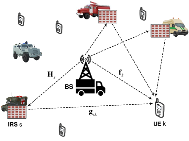
We consider a moving vehicular network where a multi-antenna BS serves a number of users with the aid of multiple surfaces. The BS is mounted on the top of a vehicle that is dedicated to providing communications service to its nearby humans or vehicles, while reflecting elements are installed on the surfaces of some other vehicles. This scenario corresponds to a platoon of interconnected combat vehicles and battle staff in the battlefield, or a group of special vehicles and rescue team members for disaster relief and emergency events. Unlike cellular networks, where intelligent surfaces are deliberately deployed on the facades of buildings, walls, and ceilings in a stationary manner, this paper is interested in a moving vehicular network where a massive number of reflection elements are embedded on vehicles’ surfaces. Since reflection elements are small, lightweight, and passive, it is easy to fabricate surfaces in any geometry, size, orientation, and arrangement. There are a plenty of large vehicles involved in either the military or emergency applications, so the implementation of IRVS is feasible.
Figure1 illustrates the schematic diagram of an IRVS-assisted vehicular network, where vehicle surfaces are deployed to assist the transmission from an -antenna BS to single-antenna user equipment (UE). Due to the orientation of vehicles, some elements might not be able to reflect the impinging signals. Without losing generality, we assume the surface has effective reflecting elements, where . Since the IRVS is a passive device, time-division duplexing (TDD) operation is usually adopted to simplify channel estimation. The users send pilot signals in the training period, such that the BS can estimate the uplink channel state information (CSI), which is used for optimizing downlink data transmission due to channel reciprocity. To characterize the theoretical performance, the analysis hereinafter is conducted under the assumption that the CSI of all involved channels is perfectly known at the BS, as most prior works [2, 8, 1, 9, 3, 10]. In addition, we assume narrowband communications, where the channels follow frequency-flat block fading. A wideband channel suffering from frequency selectivity can be transformed into a set of narrowband channels through OFDM [11], making the assumption of flat fading reasonable.
Since the direct paths from either the BS or the IRVS to UEs may be blocked, the corresponding small-scale fading follows Rayleigh distribution. Consequently, the channel gain between antenna element and user is a circularly symmetric complex Gaussian random variable with zero mean and variance , i.e., . Thus, the channel vector from the BS to the UE is denoted by
| (1) |
Similarly, the channel between the IRVS to the UE is modeled as an vector:
| (2) |
where is the channel gain between element of the surface and user , and is the large-scale fading between surface and user . We write
| (3) |
to denote the channel vector between the BS and the reflecting element of surface . So the channel matrix from the BS to the IRVS is expressed as , where the row of equals to . In contrast to hand-held UE, a surface mounted on a vehicle is generally high enough to get the line-of-sight (LOS) path of the BS without any blockage, resulting in Rician fading, i.e.,
| (4) |
with the Rician factor , the LOS component , the multipath component consisting of independent entries that follow , and the BS-IRVS path loss , .
Each reflecting surface is equipped with a smart controller, which can adaptively adjust the phase shift of each element in terms of the CSI acquired through periodic channel estimation [9]. We write to denote the reflection coefficient of the element of the surface, with the induced phase shift and the amplitude attenuation . As revealed by [2], the optimal value of reflecting attenuation is , to maximize the received power and simplify the hardware implementation. Because of severe path loss, the signals that are reflected by the IRVS twice or more are negligible. By ignoring impairments such as channel aging [12] and phase noise [13], the UE observes the received signal
| (5) |
where denotes the vector of transmitted signals over the BS antenna array, expresses the power constraint of the BS, is additive white Gaussian noise (AWGN) with zero mean and variance , namely . Define the diagonal phase-shift matrix for surface as
| (6) |
(5) can be rewritten in matrix form as
| (7) |
III Joint Optimization Design
Due to the lack of frequency-selective passive beamforming, namely the set of phase shifts cannot be tuned differently over different frequency subchannels, the use of IRVS imposes a fundamental challenge on frequency-division multiple access (FDMA). In [14], the authors revealed that time-division multiple access (TDMA) is superior to FDMA with a substantial spectral-efficiency gain. Therefore, we adopt TDMA as the multiple access scheme to analyze the IRVS-aided vehicular communications, which orthogonally divides a radio frame into time slots. Each user transmits over the entire bandwidth but cyclically accesses its assigned slot. At the header of each frame, the BS processes the uplink pilot signals to estimate the CSI. The duration of a radio frame is usually set to less than the channel coherence time, so that the CSI keeps constant for the whole frame.
At the slot, the BS applies linear beamforming , where , to send the information-bearing symbol with zero mean and unit variance, i.e., , intended for a general user . According to [15], the switching frequency of reflection elements made by PIN diodes can reach 5 megahertz (), corresponding to the switching time of , much smaller than the typical coherence time on the order of . It implies that the set of phase shifts can be adjusted specifically for the active user at each time slot. We write to denote the phase shift of the element of surface at slot , and define the time-selective phase-shift matrix as
| (8) |
Substituting and into (7), we obtain the observation of user at slot as
| (9) |

By jointly optimizing and , the instantaneous signal-to-noise ratio (SNR) of user , i.e.,
| (10) |
can be maximized, formulating the following optimization
| (11) | ||||
| s.t. | ||||
This formula is non-convex because the objective function is not jointly concave with respect to and . To solve this problem, we can apply alternating optimization that alternately optimizes and in an iterative manner [2]. Given an initialized transmit vector , (11) is simplified to
| (12) | ||||
| s.t. |
The objective function is still non-convex but it enables a closed-form solution through applying the well-known triangle inequality
| (13) |
The equality achieves if and only if
| (14) |
where stands for the phase of a complex scalar.
Define an vector to model the overall channel from all surfaces to the UE
| (15) |
where is the total number of reflecting elements over all surfaces, and the overall phase-shifts matrix at slot
| (16) |
and an channel matrix from the BS to all surfaces as
| (17) |
Thus, (14) is transformed to
| (18) |
Defining with
| (19) |
and
| (20) |
we have
| (21) |
Ignoring the constant term , (12) is transformed to
| (22) | ||||
| s.t. | ||||
The surfaces should be tuned such that the reflected signals and the signals over the direct link are phase-aligned to achieve coherent combining. Consequently, the solution for (22) is
| (23) |
Once the required phases, i.e.,
| (24) |
are determined, the optimization is alternated to update . The BS can apply maximal-ratio transmission (MRT) a.k.a. matched filtering to maximize the strength of a desired signal, resulting in
| (25) |
After the completion of the first optimization iteration, the BS gets and , which serve as the initial input for the second iteration to derive and . This process iterates until the convergence is achieved with the optimal transmit vectors and phase-shift matrices denoted by and , , respectively. Then, we can derive the achievable spectral efficiency of user as
| (26) |
and the sum rate of this IRVS-aided vehicular system as
| (27) |
III-A Discrete Phase Shifts
Although continuous phase shifts are beneficial for optimizing performance, it is practically difficult to implement. PIN diodes have been widely adopted for fabricating reflection elements due to fast response time, small reflection loss, and relatively low hardware and energy costs. By adding different biasing voltages, a PIN diode is switched to either ON or OFF state, inducing a phase-shift difference of . Finer controlling is realized by integrating multiple diodes. For example, implementing discrete phase shifts needs at least PIN diodes [16]. Higher resolution imposes not only high hardware cost and design complexity but also a large burden of wireless or wired backhaul between the BS and smart controllers. Since a surface usually contains a large number of reflecting elements, it is practical to implement only a finite number of discrete phase shifts denoted by , . Let denote the number of bits for representing different levels, the set of discrete phase shifts can be expressed as
| (28) |
with . To optimize active beamforming at the BS and discrete reflection at the IRVS, we propose to apply a two-step alternative optimization method, which gets the optimal continuous phase shifts first, and then quantizes each phase shift to its nearest discrete value. Each phase shift is quantized into a finite number of phase-control bits before sending to its corresponding smart controller through a wireless or wired link. The quantization can be simply implemented through a mid-tread uniform quantizer as
| (29) |
where the notation denotes the floor function.
III-B Random Phase Shifts
In addition to the joint optimization of passive reflection and active beamforming, we study the simplest solution as a baseline. Randomly setting the phase shifts of all reflecting elements denoted by , , each entry of which takes value uniformly and randomly from continuous phase shifts , or , that takes value uniformly and randomly from discrete phase shifts . Then, its transmit beamforming is optimized as
| (30) |
Random reflection does not need CSI acquisition, reflection optimization, and backhauling, which not only simplify the system design but also improve the network robustness, with the price of some performance loss.
IV Performance Evaluation
| , | , | |||||||||||
|---|---|---|---|---|---|---|---|---|---|---|---|---|
| TDMA | NOMA | RPS | DPS-1bit | DPS-2bit | CPS | TDMA | NOMA | RPS | DPS-1bit | DPS-2bit | CPS | |
| -likely [bps/Hz] | 1.98 | 2.21 | 8.78 | 15.42 | 16.43 | 16.82 | 4.20 | 7.76 | 14.23 | 21.83 | 22.83 | 23.14 |
| Median [bps/Hz] | 5.23 | 6.62 | 12.67 | 19.15 | 20.17 | 20.49 | 5.40 | 11.82 | 15.60 | 23.03 | 24.02 | 24.33 |
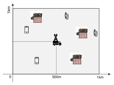
This section first presents the simulation setup and then illustrates some representative numerical results of the IRVS-aided vehicular system in terms of achievable sum spectral efficiency. As shown in Figure3, we consider a geographical area with the dimension of covered by a moving vehicular system. The BS equipped with antennas is located at the central point of the coordinate system, while or vehicle surfaces and or users are randomly, uniformly distributed in this area. Without losing generality, each surface is assumed to contain , reflecting elements. Referring to the practical LTE and NR specifications, the maximum transmit power of BS is selected to be over a signal bandwidth of , corresponding to a power density of . The variance of white noise is figured out by with the Boltzmann constant , temperature , and the noise figure .
The distance-dependent large-scale fading of the BS-UE and IRVS-UE channels, i.e., the variances and , can be computed by with path loss and shadowing fading . As [17], the path loss can be calculated by the COST-Hata model, i.e.,
| (31) |
where represents the propagation distance, and are the break points of the three-slope model, and
where the carrier frequency , the antenna height of BS , the height of IRVS , and the antenna height of UE . The break points of the three-slope model in (31) take values and , while the standard derivation for shadowing fading is . In contrast, the path loss for the LOS channel between the BS and IRVS can be computed through
| (33) |
where is the path loss at the reference distance of , means the path-loss exponent, and the Rician factor in (4) is set to .
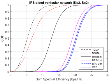
Cumulative distribution functions (CDFs) of sum spectral efficiency in bits-per-second per hertz () are evaluated as the performance metric for the IRVS-aided vehicular system. Simulation results when the phase shifts are continuous, discrete with and phase-control bits, and random are provided. To highlight the performance gain of employing vehicle surfaces, two schemes are applied as the baseline for performance comparison:
-
•
Conventional TDMA without the aid of IRVS, where the BS sends the information-bearing symbol towards the user at the slot. The antenna array applies MRT by setting to achieve matched filtering in the BS-UE direct link.
-
•
Non-orthogonal multiple access (NOMA): at the transmitter side, all information symbols are superimposed into a single waveform , where represents the power allocation coefficient. We set , subjecting to . The optimal order of successive interference cancellation (SIC) is detecting the user with the weakest channel gain to the user with the strongest channel gain. Each user decodes the weakest user first, and then subtracts its component from the received signal. In the second iteration, the user decodes the second weakest user using the remaining signal. The cancellation iterates until each user gets its own signal.
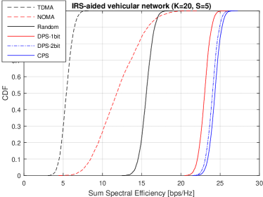
First, we observe the numerical results of a simple setup with vehicle surfaces and users, as shown in Figure4a. In our simulations, the number of iterations for alternating optimization is set to three, which is sufficient for the convergence of optimization. The -likely spectral efficiency, which is usually applied to measure the performance of cell-edge users, and the -likely or median spectral efficiency of different configurations are listed in Table I. As we expected, NOMA is superior to the conventional TDMA due to advanced signal processing (i.e., superposition coding and SIC). It is observed that the use of vehicle surfaces brings substantial performance improvement for such a moving vehicle network. Even though random phase shifts are applied, both the -likely and -likely rates increase approximately compared with the absence of IRVS. If the phase shifts are smartly adjusted, even 1 phase-control bit can bring another growth of around . Second, we also illustrate the performance evaluation of these schemes in the case of users with the aid of surfaces, as shown in Figure4b. We observe that the distribution of achievable sum rate becomes more concentrated, and the superiority of NOMA enlarges, with the increasing number of active users. In this case, the use of vehicle surfaces still bring an obvious performance improvement over NOMA and TDMA, especially for the -likely spectral efficiency. The IRVS with 2 phase-control bits results in four-fold and five-fold rate increase of -likely and -likely spectral efficiencies, respectively. In a nutshell, the numerical results justify the effectiveness and superiority of applying IRVS in moving vehicular networks.
V Conclusions
This paper focused on applying the technology of intelligent reflection surface to boost the capacity of moving vehicular networks in military and emergency communications. We presented a novel paradigm coined Intelligent Reflecting Vehicle Surface or IRVS, which integrates a massive number of reflection elements on the surfaces of vehicles. Moreover, an alternative optimization method was proposed to optimize jointly active beamforming at the base station and passive reflection at the vehicle surfaces. Performance evaluation in terms of sum spectral efficiency under continuous, discrete, and random phase shifts was conducted, in comparison with the performance of the conventional TDMA and NOMA schemes in the absence of IRVS. Numerical results revealed that the introduction of IRVS can substantially improve the capacity of a moving vehicular network, even if the IRVS operates in a blind mode with random phase shifts.
References
- [1] M. D. Renzo et al., “Smart radio environments empowered by reconfigurable intelligent surfaces: How it works, state of research, and the road ahead,” IEEE J. Sel. Areas Commun., vol. 38, no. 11, pp. 2450 – 2525, Nov. 2020.
- [2] Q. Wu and R. Zhang, “Intelligent reflecting surface enhanced wireless network via joint active and passive beamforming,” IEEE Trans. Wireless Commun., vol. 18, no. 11, pp. 5394 – 5409, Nov. 2019.
- [3] K. Zhi et al., “Uplink achievable rate of intelligent reflecting surface-aided millimeter-wave communications with low-resolution ADC and phase noise,” IEEE Wireless Commun. Lett., vol. 10, no. 3, pp. 654 – 658, Mar. 2021.
- [4] W. Jiang et al., “The road towards 6G: A comprehensive survey,” IEEE Open J. Commun. Society, vol. 2, pp. 334–366, Feb. 2021.
- [5] Y. Chen et al., “Reconfigurable intelligent surface (RIS)-aided vehicular networks: Their protocols, resource allocation, and performance,” IEEE Veh. Technol. Mag., vol. 17, no. 2, pp. 26 – 36, Jun. 2022.
- [6] A. Al-Hilo et al., “Reconfigurable intelligent surface enabled vehicular communication: Joint user scheduling and passive beamforming,” IEEE Trans. Veh. Technol., vol. 71, no. 3, pp. 2333 – 2345, Mar. 2022.
- [7] Y. Chen et al., “Resource allocation for intelligent reflecting surface aided vehicular communications,” IEEE Trans. Veh. Technol., vol. 69, no. 10, pp. 12 321 – 12 326, Oct. 2020.
- [8] M. D. Renzo et al., “Reconfigurable intelligent surfaces vs. relaying: Differences, similarities, and performance comparison,” IEEE Open J. Commun. Society, vol. 1, pp. 798 – 807, Jun. 2020.
- [9] Z. Wang, L. Liu, and S. Cui, “Channel estimation for intelligent reflecting surface assisted multiuser communications: Framework, algorithms, and analysis,” IEEE Trans. Wireless Commun., vol. 19, no. 10, pp. 6607 – 6620, Oct. 2020.
- [10] W. Jiang and H. Schotten, “Dual-beam intelligent reflecting surface for millimeter and THz communications,” in Proc. 2022 IEEE 95th Veh. Techno. Conf. (VTC2022-Spring), Helsinki, Finland, Jun. 2022.
- [11] W. Jiang and T. Kaiser, “From OFDM to FBMC: Principles and Comparisons,” in Signal Processing for 5G: Algorithms and Implementations, F. L. Luo and C. Zhang, Eds. United Kindom: John Wiley&Sons and IEEE Press, 2016, ch. 3.
- [12] W. Jiang and H. Schotten, “Impact of channel aging on zero-forcing precoding in cell-free massive MIMO systems,” IEEE Commun. Lett., vol. 25, no. 9, pp. 3114 – 3118, Sep. 2021.
- [13] W. Jiang and H. D. Schotten, “Impact of channel aging and phase noise on intelligent reflecting surface,” IEEE Commun. Lett., 2022, submitted.
- [14] B. Zheng, Q. Wu, and R. Zhang, “Intelligent reflecting surface-assisted multiple access with user pairing: NOMA or OMA?” IEEE Commun. Lett., vol. 24, no. 4, pp. 753 – 757, Apr. 2020.
- [15] L. Zhang et al., “Space-time-coding digital metasurfaces,” Nature Commun., vol. 9, no. 1, p. 4334, 1998.
- [16] Q. Wu et al., “Intelligent reflecting surface-aided wireless communications: A tutorial,” IEEE Trans. Commun., vol. 69, no. 5, pp. 3313 – 3351, May 2021.
- [17] W. Jiang and H. D. Schotten, “Cell-free massive MIMO-OFDM transmission over frequency-selective fading channels,” IEEE Commun. Lett., vol. 25, no. 8, pp. 2718 – 2722, Aug. 2021.