Large-Scale Beam Placement and Resource Allocation Design for MEO-Constellation SATCOM
Abstract
This paper presents a centralized framework for optimizing the joint design of beam placement, power, and bandwidth allocation in an MEO satellite constellation to fulfill the heterogeneous traffic demands of a large number of global users. The problem is formulated as a mixed integer programming problem, which is computationally complex in large-scale systems. To overcome this challenge, a three-stage solution approach is proposed, including user clustering, cluster-based bandwidth and power estimation, and MEO-cluster matching. A greedy algorithm is also included as a benchmark for comparison. The results demonstrate the superiority of the proposed algorithm over the benchmark in terms of satisfying user demands and reducing power consumption.
Index Terms:
MEO constellation, user clustering, beam placement, resource allocation.I Introduction
Satellite communications have become an integral part of modern communication networks, providing seamless global connectivity for a wide range of applications such as broadband internet, remote sensing, and global positioning. With the increasing demand for high data rates and low latency communications, Medium Earth Orbit (MEO) constellations have emerged as a promising solution to enhance the capacity and coverage of satellite communication systems [1]. In addition, these Non-geostationary (NGSO) constellations are equipped with next-generation payload and antenna technologies including beam placement and radio resource management (RRM) which can adapt their multi-beam capabilities to the global services [2]. However, the design of such systems is a challenging task due to the large scale of the constellation and the complexity of the system design [1]. Motivated by the advances as well as the challenges of NGSO satellite constellation, the goal of this work is to minimize the power consumption in MEO constellations while meeting the Quality of Service (QoS) requirements of all users.
The beam placement and RRM in satellite communication systems are two critical aspects that have received extensive attention in the literature. A variety of objectives have been proposed for beam placement, including minimizing half power beam footprint [3], managing inter-beam interference [4], and balancing inter-beam traffic loads fairly [5]. The diverse and changing quality of service requirements for different payloads [6, 7] have motivated the development of dynamic RRM solutions for multi-beam satellite communication systems that can accommodate irregular demands from multiple users [8, 9]. However, these solutions can be challenging to implement in large-scale systems consisting of multiple MEO payloads serving thousands of ground users.
In response to recent advancements in MEO satellite constellations, this work focuses on optimizing beam placement, user-beam mapping, and RF resource allocation for global coverage. To address this challenge, a centralized power-minimization framework is proposed for joint beam placement, power, and bandwidth allocation design in MEO constellations. The framework consists of three stages: user clustering, cluster-related bandwidth and power estimation, and MEO-cluster matching. In the first stage, a novel clustering algorithm is proposed to divide users into a number of clusters, each of which can be served by one beam from an MEO. In the second stage, the optimal bandwidth and power consumed by each MEO to meet the demand of each of its corresponding clusters are estimated sequentially. Finally, in the third stage, the MEO-cluster assignment is optimized to minimize the total power consumption, based on the optimal bandwidth and power estimates from the previous stage. The proposed framework provides an efficient power-minimization approach for large-scale MEO constellation systems while ensuring that all users receive the desired Quality of Service (QoS). A greedy mechanism is also presented for comparison purposes. The numerical results show the efficiency and superiority of the proposed algorithm over other benchmark methods.
II System Model
Let us consider a SATCOM constellation system consisting of MEO satellites serving users located on the earth’s surface. These satellites move following the equator at the height of while their longitudes, e.g., MEO , over the time can be presented as , i.e., . Let and be the sets of satellites and users, respectively. Here, one assumes that users’ demand traffic over a time window of time-slots (TSs) is available at SATCOM system, which is denoted as for user . This constellation is controlled by a ground segment consisting of multiple gateways coordinated by a central controller including an optimization module.
II-A Clustering-based Multi-Beam Satellite Communication
In this system, each satellite can create multiple beams for serving users in its coverage area. However, activating a large number of beams is not always a beneficial choice. Moreover, serving multiple users within the same beam may be beneficial in terms of user multiplexing gain. Therefore, one assumes that one beam may cover multiple users in an efficient manner instead of allocating one beam per user. To develop a clustering framework, we introduce the binary variable , which is defined as, if user and otherwise, where stands for the set of users belonging to cluster . Additionally, the clustering solution is maintained unchanged during the time window for low-complexity design and one cluster can be served by only one MEO. Once cluster associates to MEO , one specific beam focusing on this cluster will be generated by MEO . Regarding cluster-MEO association, one introduces new variable as,
| (1) |
otherwise, . To ease the presentation, let us denote as the set of all clusters, then, we have
| (2) |
II-A1 Beam Gain and Channel Gain Model
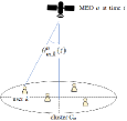
Let be the angle between the beam center of MEO satellite at time to the user in cluster . The geometry of such angle is illustrated in Fig. 1. The beam radiation pattern function between the beam and user can be formulated by following the 3GPP report [10] as
| (3) |
where indicates the maximum gain and is the normalized beam pattern gain which is computed as
| (4) |
and if , where , , represent the order-one Bessel function, the carrier wavelength, and the radius of the antenna’s circular aperture, respectively. Then, the channel gain from MEO to user can be described as where represents the path-loss.
II-A2 Achievable Rate
Denote and as the transmission power and bandwidth allocated to user at time . Then, the achievable rate of this user can be described as
| (5) |
where and stands for the noise power per Hz at the receivers. Then, the constraint on users demand can be written as
| (6) |
II-B Power Consumption Model
In our system, one assumes that the digital transparent processors (DTP) are equipped at all payloads based on which the high-power amplifiers (HPAs) and transponders can be switched off dynamically. The total power consumption of all satellites in TS is mathematically formulated as
| (7) |
where models the hardware power consumption connected to all active beams of MEO , which is consumed by various hardware components such as signal processing and HPA. Herein, is defined as
| (8) |
where is the DC to RF power efficiency of the antenna element amplifiers. Additionally, denotes the RF transmission power of beam which is computed as
| (9) |
The DC consumed power according to the onboard signal processing, denoted by , is given as
| (10) |
where represents the max DC power and í the max BW of MEO. Herein, is estimated as
| (11) |
Then, if is the same for all , which is denoted as , the total power consumption of all MEOs can be estimated as
| (12) |
II-C Problem Formulation
This work aims to develop a centralized power-minimization framework of joint beam placement, power and BW allocation for MEO-constellation which is stated as
| (13c) | |||||
| s.t. | constraints , | ||||
where and stand for the constraints on the limited power transmission and BW at every payload.
Remark 1.
This problem is a mixed integer programming which is well-known as NP-hard. Additionally, solving it optimally becomes more challenging in a large-scale global setting with the very huge number of users.
III Solution Approach
In this section, a three-stage solution approach is proposed to cope with the challenging problem given in (22). In particular, this solution consists of three stages:
-
1.
User clustering: Scheduling users into separated groups each of which can be served by one beam from an MEO.
-
2.
Cluster-related BW and Power Estimation: Estimating the optimal BW and power by an assigned-to-serve MEO to meet users’ demand in a cluster.
-
3.
MEO-Cluster Matching: Optimizing the MEO-serving-cluster assignment to minimize the total power consumption according to the optimal BW and power estimated in the second stage.
III-A User Clustering
III-A1 Potential User Clustering Matrix
Assuming the coverage of every generated beam can be defined as the footprint of -dB loss from the beam center. The users should be grouped into clusters so that the angle from a satellite to two arbitrary users in a cluster must be not greater than the beam width. Let be the adjacency matrix whose -th element, denoted by , is defined as follows
| (14) |
where represents the maximum angle from a point on satellite orbit to users and , and is the beam width. Herein, implies that users and can be served by one beam; hence, they can be grouped into one cluster. Let be the MEO orbit line, then can be defined as
| (15) |
where denotes the angle separating users and from ’s point of view and represents the orbit of all MEOs.
Remark 2.
It is worth noting that the angle from any MEO to two users and is always less than .
III-A2 User’s Required MEO Bandwidth Estimation
This section aims to estimate amount of MEO BW required to serve a specific ground user. Consider user with demand . Note that user may be located in a cluster that be covered and served by an activated beam from MEO . The coverage of that beam is defined by the footprint of -dB loss from the beam center. Here, we consider the worst case that user laying on the boundary of that beam than, . And the distance in the worst case can be defined as
| (16) |
where stands for the distance between user and MEO at time . Then, the estimated BW which should be allocated for user over the time can be presented as, , where
| (17) |
Based on , the simple clustering algorithm is presented in what follows.
III-A3 Time-Window-based Matching Efficiency Factor
In this work, one assumes that the cluster results cannot be changed during a time window of . Hence, users should be grouped into clusters so that the total required bandwidth of each cluster does not vary too much and also its average is not very far from the peak value during the time window. To do so, we present a new time-window-based matching efficiency factor as follows. Let be a set of some arbitrary users. The time-window-based matching efficiency factor corresponding to this set can be described as
| (18) |
where .
III-A4 A Simple Clustering Algorithm
In what follows, a greedy clustering algorithm is proposed to separate all users into different clusters in a manner that one beam can be placed to serve all users in a cluster and the users are grouped so that the matching efficiency factor of the corresponding cluster is as high as possible. In particular, the proposed clustering approach is summarized in Algorithm 1.
| (19) |
III-B MEO-Cluster BW and Power Estimation
III-B1 Beam Center Allocation
The beam center of each cluster can be defined simply based on the coordinates and demands of all users in cluster as follows
| (20) |
where is the calibrating factor, , and be the coordinate of user .
III-B2 Required BW and Power Estimation
Assume that MEO having coordinate is assigned to serve cluster in TS . According to and , , so-called the angle from beam center to user in TS , can be defined. Based on that, the corresponding channel gain can be estimated. Let and be the assigned BW and transmission power to serve user by MEO . Then, and can be estimated by solving the following problem.
| (21a) | |||||
| s.t. | (21b) | ||||
Theorem 1.
Problem (21) is convex
Proof:
As can be observed, is a joint concave function respected to both and . Additionally, the objective function is in the linear form of the variables. Thus, problem (21) must be convex. ∎
Hence, it can be solved optimally efficiently by employing several convex optimization tools such as CVX, Gurobi [11].
III-C MEO-Cluster Matching Design
Denote and as the solution of problem (21) for MEO and user . Then, the MEO-Cluster matching problem can be stated as
| (22a) | |||||
| s.t. | (22c) | ||||
where . This is an integer linear programming in general which can be solved efficiently by using an “off-the-shelf” optimization toolbox, or by employing a relaxation and projection approach introduced in [14, 15, 16]. Then, the proposed solution approach is summarized in Algorithm 2.
Remark 4.
III-D Greedy Solution Approach
As a point of comparison, we also created a greedy solution approach. This involves using the Voronoi clustering algorithm from [18] to divide all users into clusters. The maximum distance for each cluster is calculated based on the beam width, , and orbit height, . After the clustering is done, each cluster is assigned to its closest MEO. Finally, the bandwidth and power transmission of all users are optimized by solving problem (21) for each MEO. The whole process is outlined in Algorithm 3.
IV Numerical Results
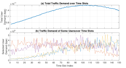
In this section, some simulations conducted for an MEO constellation of 15 payloads orbiting at an altitude of km will be provided. The simulations were run over a time frame of TSs, each lasting 6 minutes. In this simulation, the users were placed in proximity to major cities each of which contains around users. Then, there was a total of users over the world. The user demands were randomly generated based on sinusoidal patterns with peak and off-peak periods. The total demand of all users over the TSs is displayed in Fig. 2. The parameters for the simulation are listed in Table I and preliminary numerical results are also provided.
| Parameter | Value |
|---|---|
| Forward link carrier frequency | GHz |
| MEO attitude | km |
| Earth radius | km |
| W | |
| W | |
| MHz | |
| Minimum satellite elevation angle | degrees |
| Number of simulated users around a big city | |
| User terminal antenna gain | dBi |
| Temperature at user terminals | K |
| Channel Model | Refer to [12] |
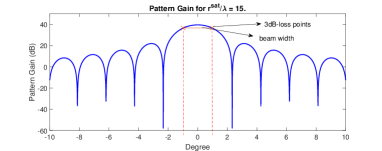
In Table II, we determine the beam width based on the radius of the antennas installed on the payload. By using the normalized beam pattern gain given in (4), the beam width is calculated as the dB loss angle, which is defined as . Figure 3 shows an example of the beam pattern gain for . It’s worth mentioning that the beam width of for is also utilized for the antenna configuration in all subsequent simulations.
| (cm) | (cm) | (cm) | (cm) | |
| (km) | (km) | (km) | (km) |
| Method | Number of Cl. | Min/Max Cl. Size | Avg. Cl. Size |
|---|---|---|---|
| Proposed Alg. | / | ||
| Voronoi [18] | / |
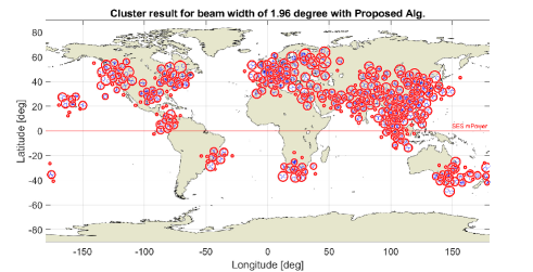
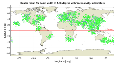
Figs. 4 and 5 demonstrate the clustering results produced by using our proposed method in Algorithm 1 and the distance-based Voronoi method from [18], respectively. These figures show the clustering results based on satellite positions and user demands in TS . The information is further outlined in Table III. Our proposed approach can be seen to generate a fewer number of beams compared to the other method.
| Method | Min/Max Clus./MEO | Ser. Clus. Ratio | Satis. User No. |
|---|---|---|---|
| Proposed Alg. | / | ||
| Greedy Alg. | / |
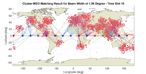
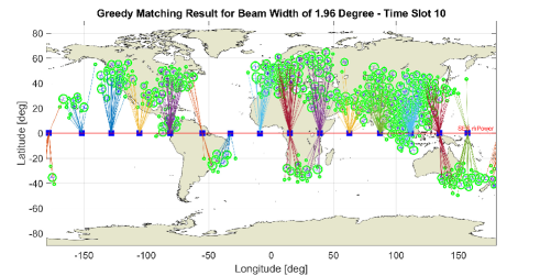
The results of Cluster-MEO matching obtained through the proposed and greedy algorithms for TS 10 are displayed in Figs. 6 and 7, respectively. The minimum and maximum number of clusters connected to an MEO, the ratios of served clusters, and the number of satisfied users are also summarized in Table IV. These figures indicate that the proposed method provides a better dynamic beam placement solution compared to the greedy algorithm. Specifically, the nearest-MEO selection framework results in an uneven load distribution across all MEOs, with some MEOs serving a larger number of clusters than others. When an MEO becomes overloaded, we propose to step-by-step remove the cluster with the highest demand until it can accommodate all remaining clusters. Interestingly, the proposed approach is able to satisfy a greater number of users compared to the greedy algorithm.

The results of the proposed algorithm during the observed time window are shown in Fig. 8. In particular, this figure illustrates the number of supported clusters, the satisfied user rates, and the number of hand-over clusters. The satisfied user rate in each time slot is calculated as the ratio of the number of users whose traffic demand is fulfilled to the total number of users in the simulation. Interestingly, the number of supported clusters and the satisfied user rate both fluctuate periodically with an average cycle duration of approximately TSs, which is also the required time for an MEO satellite to reach the position of its nearest MEO. As seen in Fig. 8-b, the high satisfactory rate, ranging from 0.976 to over 0.98, confirms the efficiency of the proposed algorithm. Additionally, Fig. 8-c shows the number of clusters that change their supporting MEO after each TS, which varies irregularly over time.

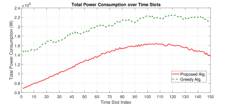
Finally, Figs. 9 and 10 illustrate the satisfied user rate and the total power consumption corresponding to the proposed and greedy algorithms over TSs. As can be observed, the proposed approach outperforms the greedy algorithm in terms of satisfying user demands and conserving energy. Our scheme is able to meet the needs of more than of the users, while the greedy algorithm only supports a maximum of , but its uses over a third of our total power consumption. Fig. 10 reveals a clear correlation between the power consumption and user demand over the time window, with higher power consumption observed during the higher-demand TSs.
V Conclusion
In conclusion, this work presents a centralized power-minimization framework for the joint beam placement, power and bandwidth allocation design in MEO constellations to meet the QoS requirements of all users. The proposed three-stage solution approach addresses the challenging NP-hard problem and provides a practical solution for large-scale MEO constellations with a large number of global users. The results demonstrate that the proposed framework effectively reduces power consumption while meeting the QoS requirements of over of users.
Acknowledgment
This work is supported in parts by the Luxembourg National Research Fund (FNR) projects FlexSAT (C19 /IS/13696663), SmartSpace (C21/IS/16193290), MegaLEO (C20/IS/14767486), and the SES-Contract project MEOBRA.
References
- [1] H. Al-Hraishawi, H. Chougrani, S. Kisseleff, E. Lagunas, and S. Chatzinotas, “A survey on non-geostationary satellite systems: The communication perspective,” IEEE Communications Surveys & Tutorials, pp. 1–1, 2022.
- [2] Y. Su, Y. Liu, Y. Zhou, J. Yuan, H. Cao, and J. Shi, “Broadband leo satellite communications: Architectures and key technologies,” IEEE Wireless Communications, vol. 26, no. 2, pp. 55–61, 2019.
- [3] N. Pachler de la Osa, M. Guerster, I. del Portillo Barrios, E. Crawley, and B. Cameron, “Static beam placement and frequency plan algorithms for leo constellations,” International Journal of Satellite Communications and Networking, vol. 39, no. 1, pp. 65–77, 2021.
- [4] B. Liu, C. Jiang, L. Kuang, and J. Lu, “Joint user grouping and beamwidth optimization for satellite multicast with phased array antennas,” in GLOBECOM, 2020, pp. 1–6.
- [5] V.-P. Bui, T. Van Chien, E. Lagunas, J. Grotz, S. Chatzinotas, and B. Ottersten, “Joint beam placement and load balancing optimization for non-geostationary satellite systems,” in IEEE MeditCom, 2022.
- [6] S. Xia, Q. Jiang, C. Zou, and G. Li, “Beam coverage comparison of leo satellite systems based on user diversification,” IEEE Access, vol. 7, pp. 181 656–181 667, 2019.
- [7] H. Nguyen-Kha, V. N. Ha, E. Lagunas, S. Chatzinotas, and J. Grotz, “Leo-to-user assignment and resource allocation for uplink transmit power minimization,” in IEEE WSA & SCC 2023.
- [8] L. Chen, V. N. Ha, E. Lagunas, L. Wu, S. Chatzinotas, and B. Ottersten, “The next generation of beam hopping satellite systems: Dynamic beam illumination with selective precoding,” IEEE Transactions on Wireless Communications, 2022.
- [9] V. N. Ha, T. T. Nguyen, E. Lagunas, J. C. Merlano Duncan, and S. Chatzinotas, “GEO payload power minimization: Joint precoding and beam hopping design,” in GLOBECOM 2022 - 2022 IEEE Global Commun. Conf., 2022, pp. 6445–6450.
- [10] “ Study on new radio (NR) to support nonterrestrial networks,” 3GPP TR 38.811 V1. 0.0, Stage1 (Release 15), 2018.
- [11] H. Nguyen-Kha, V. N. Ha, E. Lagunas, S. Chatzinotas, and J. Grotz, “’leo-to-user assignment and resource allocation for uplink transmit power minimization,” in 2023 IEEE ICC Workshops (GC Wkshps), 2023.
- [12] P. Angeletti and R. De Gaudenzi, “A Pragmatic Approach to Massive MIMO for Broadband Communication Satellites,” IEEE Access, vol. 8, pp. 132 212–132 236, 2020.
- [13] E. Lagunas, V. N. Ha, T. V. Chien, S. Andrenacci, N. Mazzali, and S. Chatzinotas, “Multicast MMSE-based precoded satellite systems: User scheduling and equivalent channel impact,” in 2022 IEEE 96th Veh. Tech. Conf. (VTC2022-Fall), 2022, pp. 1–6.
- [14] V. N. Ha and L. B. Le, “End-to-end network slicing in virtualized OFDMA-based cloud radio access networks,” IEEE Access, vol. 5, pp. 18 675–18 691, 2017.
- [15] M. Sanjabi, M. Razaviyayn, and Z.-Q. Luo, “Optimal joint base station assignment and beamforming for heterogeneous networks,” IEEE Trans. Signal Process., vol. 62, no. 8, pp. 1950–1961, 2014.
- [16] V. N. Ha, D. H. N. Nguyen, and J.-F. Frigon, “Subchannel allocation and hybrid precoding in millimeter-wave OFDMA systems,” IEEE Trans. Wireless Commun., vol. 17, no. 9, pp. 5900–5914, 2018.
- [17] V. N. Ha and et al., “Joint linear precoding and DFT beamforming design for massive MIMO satellite communication,” in 2022 IEEE Globecom Workshops (GC Wkshps), 2022, pp. 1121–1126.
- [18] N. Ma, H. Zhang, H. Hu, and Y. Qin, “Escvad: An energy-saving routing protocol based on voronoi adaptive clustering for wireless sensor networks,” IEEE Internet of Things Journal, vol. 9, no. 11, pp. 9071–9085, 2022.