SkinSense: Efficient Vibration-based Communications Over Human Body Using Motion Sensors
Abstract.
Recent growth in popularity of mobile and wearable devices has re-ignited the need for reliable and stealthy communication side-channels to enable applications such as secret/PIN sharing, co-location proofs and user authentication. Existing short-range wireless radio technology such as Bluetooth/BLE and NFC, although mature and robust, is prone to eavesdropping, jamming and/or interference, and is not very useful as a covert communication side-channel. This paper designs and implements SkinSense, a vibration-based communication protocol which uses human body/skin as a communication medium to create a low-bandwidth and covert communication channel between user-held mobile and wearable devices. SkinSense employs a novel frequency modulation technique for encoding bits as vibration pulses and a spectrogram-based approach to decode the sensed motion data (corresponding to the encoded vibration pulses) to reconstruct the transmitted bits. SkinSense is comprehensively evaluated for a variety of operational parameters, hardware setups and communication settings by means of data collected from human subject participants. Results from these empirical evaluations demonstrate that SkinSense is able to achieve a stable bandwidth of upto 6.6 bps, with bit error rates below 0.1 in our custom hardware setup, and can be employed as a practical communication side-channel.
1. Introduction
The ubiquity of smart wearables has rapidly increased in the past few years, wherein inexpensive devices such as smartwatches, fitness bands, smart-glasses, and smart-shoes provide users with a variety of additional capabilities beyond that of a smartphone. Apart from a small subset of these smart wearables which can operate autonomously, the vast majority of smart wearables are used in conjunction with a paired user-held mobile device such as a smartphone. Currently, this communication between the mobile device (smartphone) and paired smart wearables is primarily accomplished using short-range wireless radio technology such as Bluetooth/BLE, NFC, and Wi-Fi. Although these technologies are very mature and enable robust communication between mobile devices, wireless radio signals are prone to eavesdropping, jamming and/or interference, resulting in loss of communication or privacy or both. There is a genuine need for reliable and stealthy non-radio communication side-channels in several use-cases and applications involving these devices. For instance, a low bandwidth, non-radio based protocol could be used to swiftly and securely send a short secret code or a PIN from a smartphone to a smart wrist wearable to automatically initiate and establish a high-bandwidth and secure radio channel, such as Bluetooth or WiFi. Besides secret sharing, the availability of such an out-of-band communication side-channel could prove to be convenient and practical for several other security applications such as proof of device co-location and user authentication. Some recent proposals on alternate body-area communication channels have suggested the use of optical (Chevalier et al., 2015b, a) and acoustic signals (Laput et al., 2016; Galluccio et al., 2012) to enable low-bandwidth message transfers between mobile devices. Such communication channels, however, are not robust and often perform poorly in the presence of noise or non-ideal ambient conditions, and are not very covert (i.e., easily detectable) (Rushanan et al., 2014).
Other proposals in this direction have employed vibration motors, often embedded in mobiles devices to provide haptic feedback to users, as a transmitter (Hwang et al., 2012; Roy et al., 2015; Roy and Choudhury, 2016; Ma et al., 2020). In such techniques, fine-grained motion sensors such as accelerometers and gyroscopes (also found on most modern mobile devices) have been adopted as receivers (Michalevsky et al., 2014). Hwan et al. (Hwang et al., 2012) were one of the first to propose the pairing of a vibration motor and an accelerometer to establish a protocol for low-bandwidth communication between two smartphones kept on the same (hard) surface. Roy et al. (Roy et al., 2015) followed up by proposing a scheme, called Ripple, which provided improved bandwidth and added security. Kim et al. (Kim et al., 2015) proposed the use of a smartphone as a vibration transmitter for a custom medical device with an accelerometer implanted under the skin acting as the receiver. Later, Sen and Kotz (Sen and Kotz, 2020) proposed the use of a smart ring as a vibration transmitter to communicate with Internet-of-Things (IoT) devices equipped with accelerometers, however for their scheme to work, the transmitter (smart ring) needed to be in direct contact with the receiver (IoT device) for reliable communication.
In this work, we take inspiration from these earlier research efforts to explore the feasibility of employing vibration motors and accelerometers to build a reliable communication protocol between two user-held mobile devices (e.g., a smartphone and a wrist wearable), by using the human body/skin as the underlying physical medium for vibration signal propagation. Given that modern mobile devices such as smartphones and wearables are always in contact with the human body/skin, and that they come pre-equipped with vibration motors and motion sensors, such a communication technique could be naturally deployed without requiring any special setup/hardware. Also, as the user’s own body/skin acts as a communication channel, the scheme would be naturally covert and robust against trivial eavesdropping.
Although vibration-based communication techniques have been proposed before, additional research and experimentation is required to build a robust (against noise and movements) and easy-to-deploy communication system that employs vibrations traveling through human skin/body, which is what this work attempts to accomplish. To this end, the main challenges include identifying how vibrations can be modulated so that they can effectively propagate via human skin/body, and efficiently using an accelerometer to sense these vibrations in the presence of volatile body movements. Moreover, inherent anatomical and biomechanical differences between individuals can also affect the efficiency of the communication channel. Consequently, the main requirements as we design such a communication technique are: (a) robustness to vibration noise and anatomical differences that are inherently present in human body/skin, (b) a sufficient level of data rate suitable for low-bandwidth communications, and (c) reliable communication under mobility such as while traveling in a vehicle.
Our key contribution in this paper is the design, implementation and evaluation of a novel vibration-based communication protocol, called SkinSense, which utilizes human body/skin as a communication medium in order to create a low-bandwidth and covert communication channel between user-held mobile and wearable devices. We demonstrate the feasibility and performance of SkinSense by employing both a custom hardware setup, which enables the flexibility of being able to manipulate the different hardware and protocol parameters for a comprehensive evaluation, and consumer-level devices. By collecting data from a diverse set of human subject participants, we comprehensively evaluate SkinSense under different/varying operational parameters and communication settings, including, distance between transmitter and receiver, device orientation, ambient noise, sampling rate, communication direction and motion sensing hardware (accelerometer versus gyroscope). In addition to this, we also conduct an in-depth analysis of the impact of the various SkinSense design parameters on communication performance and error rates, empirically evaluate its vulnerability to acoustic or Sound of Vibration (SoV) attacks, and study its energy requirements. Lastly, we systematically compare the performance of SkinSense with other efforts in the literature and conduct a small user-study to gauge the perception and preferences of end users using such a communication side-channel.
2. Background
We now briefly introduce some background information relevant to our proposed communication protocol.
2.1. Vibration Motor
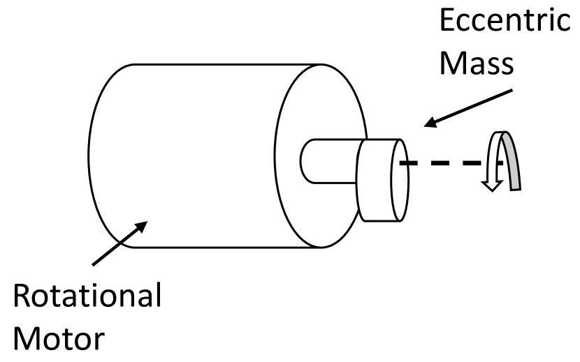
A vibration motor is a mechanical device that uses motion from an unbalanced metallic mass to produce oscillations or vibrations (Gao et al., 2021). They are usually found inside most modern mobile devices such as smartphones and smartwatches to provide haptic feedback or notifications to users. There are two main types of vibration motors: (i) Eccentric Rotating Mass (ERM) motors, and (ii) Linear Resonant Actuator (LRA) motors. ERM motors are powered by direct current (DC) and employ an asymmetric mass (Fig. 1(a)) which moves eccentrically when rotated (Seim et al., 2015). The amplitude and frequency of the vibrations can be controlled by varying the input DC voltage, and they both increase with higher voltages (Ali and Liu, 2021; Roy et al., 2015). LRA motors, on the other hand, consist of a magnetic coil that pushes a mass up and down to create vibrations, enhanced by a spring. LRA is driven by a precise amount of AC current so as to achieve resonant frequency of the spring, which limits the vibration motor’s amplitude and frequency within a very narrow band. Huang et al. (Huang et al., 2016) showed that ERM motors are better suited for applications requiring complex encoding of the vibration signal, compared to LRA motors which work well only for simple binary encoding. Therefore, we employ an ERM-based DC coreless motor in this work.
Motor Control. Pulse Width modulation (or PWM), a technique to reduce the average power delivered to a load by effectively breaking the input electrical signal into discrete parts, is often used to control intertial loads such as vibration motors found in most mobile devices (Barr, 2001; Luo et al., 2018). The average value of voltage (and current) supplied to a motor in PWM is regulated by turning the switch between the power supply and the motor ON and OFF at a fast and variable rate. In other words, PWM can control the operation of a motor by providing it with a series of electrical pulses or “ON-OFF” signals. The power to the motor is controlled by varying the width of these pulses, which in turn, varies the average DC voltage applied to the motor. Ultimately, PWM enables greater control over the motor without altering the voltage level of the supply voltage, which is ideal for encoding signals over motor vibrations. We utilize a selected range of PWMs to control the motor based on the feedback observed via vibration signals captured using motion sensors, as discussed later in Section 3.3.
2.2. Accelerometer
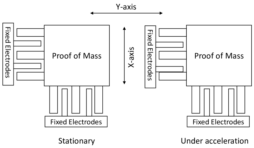
Accelerometers are used to measure acceleration or speed changes of a device with respect to the surrounding environment. Most modern mobile and wearable devices are equipped with micro-electromagnetic (or MEMS) (D’Alessandro et al., 2019; Varanis et al., 2018) accelerometers, which enable applications ranging from simple step counting to complex activity recognition (Shoaib et al., 2016). There are two main types of MEMS accelerometers in use today: (i) piezoresistive accelerometers, and capacitive accelerometers (Gao and Zhang, 2004). Piezoresistive accelerometers consist of a mass attached to a piezoelectric crystal. When vibrations or movements occur on the accelerometer, while the mass itself remains unchanged, it makes the crystal either compress or stretch depending on the direction and magnitude of acceleration. Capacitive accelerometers (Fig. 1(b)) consist of a proof-of-mass suspended between two plates, one which is fixed and other which is free to move inside the accelerometer housing. When vibrations/movements occur on the accelerometer, the distance between the plates change proportionally to the acceleration, resulting in a change of capacitance (Venkatanarayanan and Spain, 2014). Most modern devices are equipped with capacitive accelerometers due to their smaller size and ability to measure low-frequency motion (D’Alessandro et al., 2019). Accelerometers produce raw measurements along three axes, with gravity components applied to whichever axis is pointing to the ground. Another type of motion sensor commonly found in consumer mobile devices is the gyroscope, which in contrast to accelerometers, measures a device’s angular velocity. Later in Section 4, we comparatively evaluate our proposed communication protocol using both the accelerometer and gyroscope sensors.
2.3. Mechanics of Vibrations
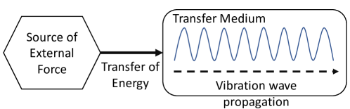
Vibrations are a form of mechanical oscillations, defined as repetitive back and forth movement of an object between two states or positions about an equilibrium point (Rittweger, 2020). There are 2 kinds of vibrations, free and forced. Free vibrations occur as a result of a brief energy transfer from an external force on to an object (e.g., one time picking of a guitar string) (Rittweger, 2020). In contrast, forced vibration is a continuous periodic external force applied to an object (e.g., repeatedly pushing a playground swing). Vibrations can be fully described using two parameters, namely, frequency and amplitude. Frequency of vibration describes how fast the vibrating object is moving, while amplitude is the maximum displacement of the vibrating object in motion, i.e., the strength of the vibrations. When an object vibrates, its particles are disturbed by the vibrational energy propagating from one point of the object to another, also called the vibration wave (Fig. 2). How well these waves propagate through the object (or medium) depends on its molecular structure (such as density). If an object has tightly packed molecules, it is known to have a higher rigidity (e.g., wood or steel). Such objects or mediums are better at transmitting vibration waves making them travel farther, faster and longer compared to less rigid mediums (e.g., a cushion pillow) (Blake, 1961). Vibration waves have a characteristic wavelength (), which is the distance between two adjacent crests (highest points) of the wave. When a wave travels from one medium to another, although the wavelength changes, the frequency remains unchanged (Rittweger, 2020). This is defined as , where is the velocity and is the frequency of the wave. Thus, the velocity and wavelength of the vibration waves originating from some source and transferring to an object/medium could change depending on the rigidity of the object.
In this work, we are attempting to leverage vibrations originating from a handheld device such as a smartphone to design a communication mechanism, where the vibration waves propagate to the receiver through the skin of the hand (holding the handheld). Previous works on vibration-based communication schemes have employed objects such as wooden tables as the transmission medium (Roy et al., 2015). These efforts have been able to achieve very high data rates and accuracy, primarily because wood is a good propagation medium for vibration waves due to its high rigidity. In contrast, human skin absorbs more vibrations due to its lower rigidity, making it less desirable as a transmission medium for vibration waves (Ali and Liu, 2021). Consequently, designing a vibration-based communication scheme relying on the propagation of the vibration waves through the human skin is a much more challenging endeavor. Prior studies have shown that the propagation of vibration waves via the human skin is correlated to the vibration frequency of the source, and that the vibration decay is quicker at low and high frequencies (i.e., vibrations cannot propagate for longer distances) compared to intermediate frequencies of the source (Shah et al., 2019; Manfredi et al., 2012). Since our work considers a communication scenario of a handheld device and a wrist wearable, which naturally results in a certain amount of distance (with distances ranging from 15 cm to 2 cm depending on the motor placement on the handheld device) between the two devices when worn on the hand, understanding and analyzing this vibration decay and the effect of vibration frequency was important in designing an effective communication framework. In order to identify these intermediate frequencies which would help in designing SkinSense, we do a sine sweep test as explained further in Section 3.2.
Based on the high-level discussion so far on the mechanics of vibrations, we now formally describe how vibrations created by motors (e.g., ERM motors) can be used to send vibration waves (or signals) through human skin as a medium. The centrifugal force generated by an ERM motor is given by:
where is the force (in ), is the mass of the eccentric mass (), is the radius of the eccentric mass () and is the angular velocity (speed of the motor) in (Rittweger, 2020). As and are physical properties of the motor that cannot be changed, the centrifugal force generated by the motor can only be changed by manipulating the angular velocity, . The vibration frequency and amplitude in an ERM motor cannot be changed independently and they both increase linearly based on the voltage provided. ERM motor speeds are proportional to the applied voltage, therefore amplitude/frequency changes can be done by manipulating the voltage via pulse width modulation (PWM) as discussed above in Section 2.1. As clarified earlier, identifying a set of intermediate frequencies that propagates well from a handheld device to a wrist wearable via human skin as the medium is the first step in designing an effective communication scheme via skin. To modulate a set of frequencies, we rely on a PWM based technique and then use these different frequencies to encode data in SkinSense as described in detail in Section 3.
3. System
We now present the design and other technical details of SkinSense by first providing an overview of the system architecture, followed by design details of the communication protocol. We then present the technical details of the encoding (modulation) and decoding (demodulation) algorithms followed by an outline of different hardware setups that we employ in the implementation of SkinSense. Finally, we present details of the human subject data and performance metrics used in its evaluation.
3.1. System Overview
Fig. 3 shows a high-level overview of SkinSense enabling vibration-based communication between a handheld device and a wrist wearable by using the user’s hand (specifically, the skin tissues) as the communication channel. We consider a half-duplex communication channel, i.e., the handheld device and wrist wearable can both act as a transmitter and receiver, however information can flow in only one direction at a time. Moreover, we consider that the communicating devices are located on the same hand, but they do not need to be in physical contact with each other. The message that needs to be transmitted from the handheld device to the wrist wearable (or vice versa) is first encoded into a stream of vibration signals by using an encoding (or modulation) algorithm described in Section 3.3.1. The vibration motor on the transmitting device then emits these vibration signals, which is carried via the skin tissues of the hand to the receiving device. The receiving device’s motion sensor records these vibrations and decodes the encoded message using a decoding algorithm outlined in Section 3.3.2.

3.2. Transmitter Design
Our final transmission algorithm was arrived at after many rounds of iterations and preliminary investigations where we scrutinized on how vibrations travel through the human skin and its ability to be captured by an accelerometer. As a first step, our goal was to examine the possibility of identifying/differentiating multiple vibration frequencies for data encoding, which would effectively allow us to significantly increase the bandwidth of our communication protocol (compared to using only a single frequency encoding scheme). Specifically, we analyzed how vibrations of different frequencies, after being generated by the motor and traveling via the skin, gets captured on an accelerometer. Once specific operable frequencies with clear separations were identified, our next goal was to minimize the vibration times, i.e. the time of a single vibration pulse (ON times) and the interval between two vibration pulses (OFF times). At the same time, to further increase the bandwidth and data rate, we also found that time domain data encoding could also be used in conjunction to frequency-based encoding by reliably determining vibration ON times and OFF times. The specific details of selecting operating frequencies and time modulation are presented next.
3.2.1. Identifying the operable frequencies
In order to identify and characterize the range of frequency bands to operate the transmitter motor in, such that the receiver accelerometer would have a distinct response to the vibration signal, we did a sine sweep test (Roy et al., 2015) by test operating the motor in the range of 20 (low) to 240 (high) PWM values and analyzed the corresponding accelerometer signal at the receiver.
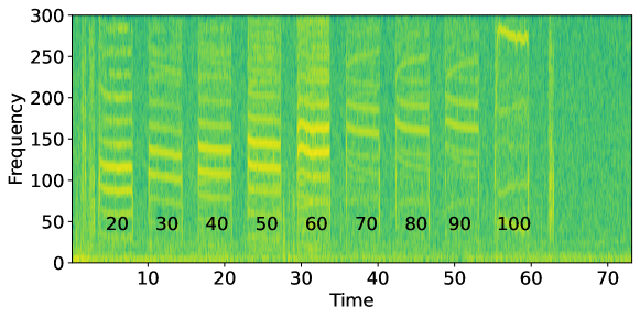
We observed that the frequency response captured by the accelerometer peaks around PWM 60 and fades away starting around PWM 100 (refer Fig. 4). Based on this observation, we determined that the motor reaches its resonant frequency at around PWM 60. While a simple ON or OFF binary encoding mechanism would only require one operational frequency for the motor, this will limit the amount of data that can be encoded using vibrations. After identifying the operable frequencies to be in the range of PWM 20-100, we then closely analyzed which specific PWM frequencies to work with. For the frequency analysis, we closely observed the frequency response of PWMs from 20 up to 100 in steps of 10. We subsequently found PWMs 20, 30, 60 and 100 to be the ones with minimal interference with neighboring PWMs, and thus employ them as the final set of PWM parameters in SkinSense implementation.
3.2.2. Time based modulation
We next studied the possibility of minimizing the ON time and OFF time of the vibrations to further increase the data rate. For that, we analyzed how accurately we can infer the ON time and OFF time windows of vibrations using the accelerometer signal for a range of ON and OFF time values. These ON and OFF times are affected by a phenomenon called the ringing effect (Roy et al., 2015), where the vibration may remain in the medium for sometime before completely dying down when the voltage is cut off to the motor. When choosing OFF times, we need to specifically select values that accommodate the remnants of the previous vibration pulse such that, the next vibration pulse is not affected by it to prevent inaccuracies during demodulation. We tested OFF times in the range of 150-1000 ms and were able to clearly distinguish between OFF time values of 250 ms, 500 ms, 750 ms and 1000 ms. Any values lower than 150 ms proved to be too short, leading to interference between consecutive vibration pulses. Therefore, without affecting the overall accuracy, we select 150 ms and 300 ms as the OFF time window values in our algorithm implementation. After finalizing appropriate OFF time values, we determine ON time window values, i.e. the amount of time the vibration motor stays on in a single window. Similar to the OFF time analysis, we tested ON times in the range of 250-1000 ms, followed by ON time values below 250 ms, however values below 250 ms proved to be too small to be accurately identified in the accelerometer signal. Thus, without affecting the overall accuracy, we fixed 250 ms and 500 ms as the ON time window values for our implementation. The full hardware setup used for this analysis is detailed in Section 3.4.1. An independent analysis may be required to determine the optimal parameters for each motor-accelerometer pair since different motor types may have varying resonant frequencies, and different accelerometer types may have varying sensitivities.
3.3. Communication Algorithms
SkinSense employs a PWM based frequency modulation technique for encoding bits as vibration pulses and a spectrogram based approach to decode the sensed motion data (corresponding to the vibration pulses) to reconstruct the transmitted bits, as outlined next.
3.3.1. Encoding Algorithm
The transmission algorithm takes as input a sequence of bits to be transmitted and outputs a sequence of parameters (PWMs, ON times and OFF times) to be passed on to the vibration motor. The PWMs are a measure of the voltage given to the motor, which in turn controls its frequency. The ON times signify the time in milliseconds (ms) for which the vibration motor is switched on, while the OFF times signify the time in milliseconds between two consecutive vibration pulses. By modulating these three parameters independently, we are able to transmit the bit string as a series of vibrations of differing times and frequencies.
SkinSense currently uses four values of PWMs (20, 30, 60, 100), two values of ON times (250 ms, 500 ms) and two values of OFF times (150 ms, 300 ms) for modulation, as described earlier in Section 3.2. As a result, we are able to encode bits using the PWM values and bit using the ON time and OFF time values, respectively. In order to transmit a bit sequence using the above setup and set of parameters, we need to partition it into 4-bit long words. Then, we encode each 4-bit word as follows: The first two bits of the word are encoded using one of the four PWM values, the third bit using one of the two ON time values and the fourth bit using one of the two OFF time values. At the end of transmitting message, we append a pilot sequence to improve accuracy while decoding.
3.3.2. Decoding Algorithm
The decoding algorithm takes as input the raw accelerometer values sensed at the receiver and outputs the decoded bit sequence. The sequence of steps involved in the decoding algorithm are as follows:
-
(1)
Spectrogram computation: Raw signal filtering and normalization.
-
(2)
Peak detection: Deriving the encoded parameters.
-
(3)
Symbol separation: Symbol separation to identify the encoded PWM values, ON time values and OFF time values.
-
(4)
Pilot sequence based mapping and decoding: Decode the message by generating the corresponding bits associated with each PWM values, ON time values and OFF time values.
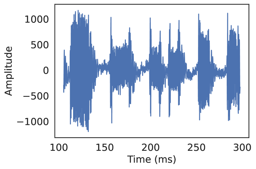
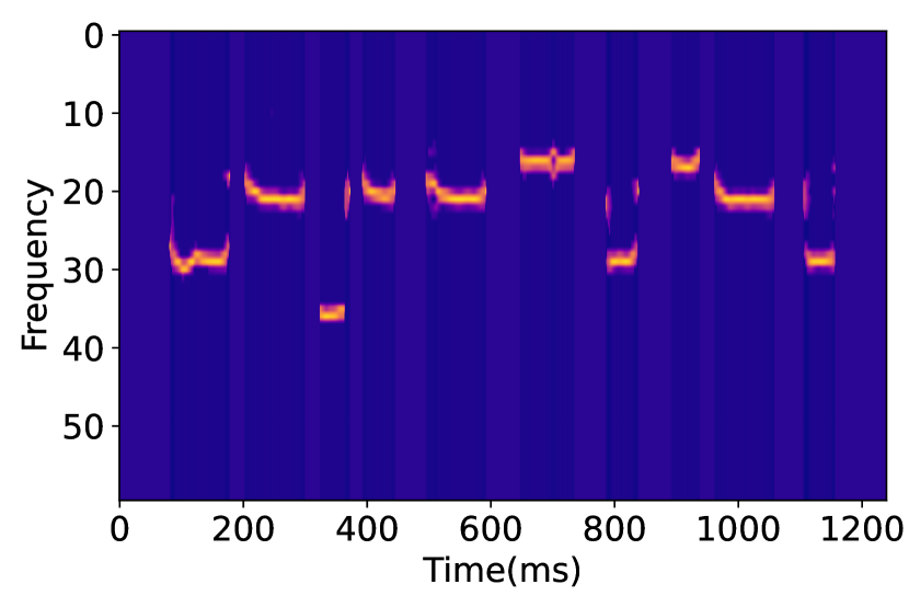
Spectrogram. The spectrogram of raw accelerometer time-series data samples are first computed in the decoding process. Essentially, a spectrogram is a matrix which depicts the strength of the accelerometer signal over time at different frequencies (a spectrum of frequencies), i.e., each position of the matrix corresponds to a point in frequency and time. In other words, the time-series data is converted from the time domain to the frequency domain (using FFT with a window size of 128 samples and an overlap of 124 samples). In order to reduce the effect of noise, we filter out all frequencies below 40 Hz from the spectrogram. These frequencies fall below our band of operation and correspond mainly to low frequency noise which may be present in the human hand. Fig. 5 shows the frequency spectrum before and after removing this noise. We then perform mean and variance normalization on the resulting spectrogram in order to eliminate any constant biases that may be present.
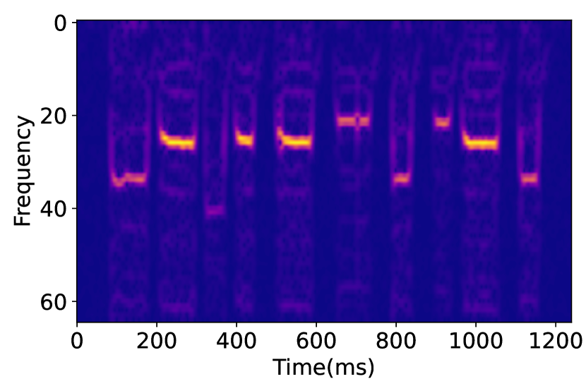
Peak Detection. In order to determine the PWM values used during encoding, we rely on the fact that the frequency of the vibrations are linked to the PWM. By accurately determining these frequencies, we can estimate the PWM value. It was observed that for most PWM values, there are two frequencies where there is a significant amount of energy present. This can be observed in the Fig. 4, the two darkest yellow bands for each PWM represent these two frequencies. They represent the two most prominent overtones of the vibrations passing through the hand (overtones are any frequencies higher than the lowest frequency present in the signal (Bloothooft et al., 1992)). Due to the presence of two prominent overtones, in order to derive the frequency of the vibration at any point in time, our algorithm detects the two most prominent peaks in the spectrogram and computes the mean of the frequency of these two overtones to obtain a close estimation of the transmitted frequency. However, at higher PWMs (e.g., 100), it was noticed that only one overtone contains a majority of the energy. In order to handle these cases, the algorithm compares the frequencies of two most prominent peaks, and only if the second most prominent peak is of the same order of magnitude as the most prominent one, the mean of the two frequencies is computed. Otherwise, it simply considers the frequency of the most prominent peak for the frequency estimation.
Symbol Separation. From the previous peak detection process, we obtain a vector (denoted as ) of the detected frequency for each time window. In time windows without any vibration, the frequency is set to . We then use the following heuristic to separate out the transmitted symbols, in the form of ON times, OFF times and PWMs. First, the first and last time windows of each vibration are computed by using the symbol separation algorithm (Algorithm 1). Then, the ON times, PWMs and OFF times are computed by using this information. In order to negate any effects of short-duration impulsive noise, we discard any symbols whose ON times are smaller than 200 ms. We do this filtering because the shortest possible length of a transmitted symbol is 250 ms as per the ON time values we have chosen for transmission, which implies that ON times smaller than 200 ms are noise.
Pilot Sequence based Mapping and Decoding. As mentioned earlier, a pilot sequence is appended to each message to improve accuracy at the time of detection. Due to a variety of reasons, such as the frequency response of the user’s hand, the precise orientation, tightness of the watch, and the time taken by the motor to ramp up and ramp down, there could be considerable variance in the received parameters with every use of the communication system. Hence, we use this pilot signal during decoding to measure any offsets in the transmitted parameters and adjust them accordingly. The pilot signals consists of the following sequence of ON times, OFF times and PWMs, respectively: ON time values: [250,500,250], OFF times values: [150,300], PWM values: [20,30,60].
These encompass most of the parameters used to transmit information in our system. At the receiver, this pilot sequence first undergoes the spectrogram based filtering, peak detection based frequency estimation followed by symbol separation to identify the parameters used in the pilot sequence. These values obtained are then used as a mapping to decode the actual message. We start with the pilot sequence, where each value in the estimated parameter set of the pilot sequence is mapped to its corresponding value from the original parameter set . By using this information, the output of the symbol separation algorithm is then mapped to their corresponding parameters as follows: For each estimated parameter in the estimated parameter set for the transmitted message , if , is mapped to , else, is mapped to . For example, for PWM values of the pilot sequence, the symbol separation algorithm may output the following values, 24, 35, 66. Now since we know that pilot sequence can only have PWM values 20, 30 and 60 and the order of their occurrence, we map these estimated values to each corresponding PWM value. Then, for the actual message, if an estimated PWM value is 27, it is mapped to the pilot sequence estimated value of 24 (via the above described method) which corresponds to PWM 20 of the original encoding parameter value. The same procedure is followed for other parameter sets, and . Finally, the message is decoded by reconstructing 4-bit long words for each PWM, ON and OFF combination of values obtained from the mapped symbol separation output, i.e., the first 2 bits of a word are derived based on the PWM value, while the third and fourth bits are derived using the ON time and OFF time value, respectively.
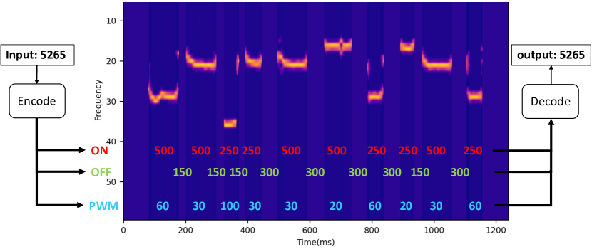
A sample PIN transmission. Fig. 6 instantiates the aforementioned algorithms of SkinSense with a real example, wherein a 4-digit PIN is first encoded into a vibration pattern (consisting of ON, OFF, and PWM parameters) and then transmitted. A spectrogram composed from the received accelerometer signal is then used to detect the relevant ON, OFF, and PWM parameters based on the vibration pulses, which are then used to successfully decode and output the original PIN.
3.4. Implementation Hardware
To comprehensively evaluate SkinSense, we implement two different hardware setups. To enable an exhaustive investigation of the performance for a variety of fine-grained transmitter and receiver parameters, we first implement and evaluate SkinSense in a custom hardware setup (Section 3.4.1). Then to evaluate SkinSense in a realistic setting, we implement a consumer hardware setup (Section 3.4.2) comprising of commercially available mobile and wrist wearable devices.
3.4.1. Custom Hardware Setup
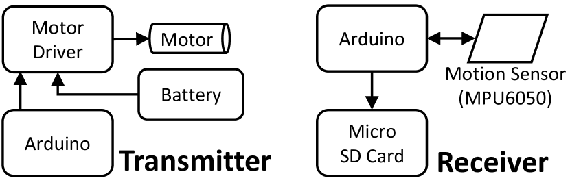
We implement this setup by building custom devices closely resembling transmitters and receivers on commercial handheld devices (e.g., smartphones) and wrist wearables (e.g., smartwatches). In this setup, we use Arduino Uno and Nano boards to control the transmitter and the receiver, respectively. For the transmitting vibration motor, we use an ERM motor (16000 RPM) connected to the Arduino Uno board via a L298 motor driver (Components101, 2020), powered using a 12V (5 Amp-Hours capacity) Lead Acid battery. We use a 12V battery to power the motor to achieve longer operating times for our experiments. However, as the motor operates in the range of 1.5V to 3V it can also easily be powered using two (1.5V) AAA batteries. We power the Arduino Nano board (the receiver device) via a 5V USB input. To build the custom handheld device prototype, we use a consumer level smartphone case (Fig. 7(b)) on which we mount the vibration motor. For the custom wrist wearable prototype, we use a Sony Smartwatch 3 Band (the smartwatch portion removed, see Fig. 7(b)) to mount the motion sensor. For both the custom devices, we use a MPU6050 GY-521 MEMS motion sensor containing a three-axis accelerometer and a three-axis gyroscope. The motion sensor is also connected with a Micro-SD card using an Arduino Micro-SD card adapter (via SPI mode) for data recording purposes. As explained earlier (Section 2), we use a PWM technique to control the operation of vibration motor. The sampling rate of the motion sensor achieved when writing to the Micro-SD card is 700 Hz. To evaluate communication in the reverse direction (i.e. wrist wearable to handheld device), we swap the motor and motion sensor between the two custom devices.
3.4.2. Consumer Hardware Setup
For this setup, we use a Nokia 6 (2017) smartphone as the handheld device and a Sony Smartwatch 3 as the wrist wearable. The Sony Smartwatch can only achieve a maximum sampling rate of 200 Hz, in contrast to the sampling rate of 700 Hz that we were able to achieve using the custom hardware setup. Moreover, in these devices the Android API only provides control of the motor’s vibration amplitude, but not of the frequency. Similar to Roy et al. (Roy et al., 2015), we looked into the possibility of modulating the amplitude to encode data. However as mentioned earlier, due to sampling rate limitations in consumer level smartwatch accelerometers, we were not able to accurately differentiate between different amplitudes just by using the accelerometer data. This effectively limits the full implementation of the SkinSense communication protocol on these devices as we rely on multiple frequencies to encode data.
3.5. Human Subject Data Collection
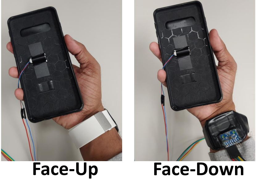
We perform a comprehensive empirical evaluation of SkinSense using data collected from human subject participants in realisitic settings and environments. For our data collection study, we recruited 13 participants in the age group of 18-29 from our university campus. Participants in our study wore the custom wrist wearable device on the wrist of one hand (preferred by the participant) and held the custom handheld device (Fig. 7(b)) in the palm of the same hand. In this setup, binary data was communicated from the handheld device to the wrist wearable, and vice versa, using our proposed vibration-based approach under a variety of different ambient/device settings and algorithm parameters.
In our first experimental setup, we evaluate the effect of two different orientations of the wrist wearable device on the performance of the communication scheme. The first orientation is the case when the wrist wearable is worn facing upwards along the top of the forearm (or wrist), while the second orientation is when the wrist wearable is facing downwards along the bottom of the wrist (see Fig. 7(b)). As different users may prefer to wear their wrist wearables in different orientations and, depending on the orientation of the wrist wearable the position of the vibration motor and accelerometer on the wrist/forearm may change impacting the performance of SkinSense, it is important to further analyze these setups. In the second experimental setup, we test the effect of distance between the transmitter (vibration motor) and receiver (accelerometer) devices on SkinSense’s performance. Accordingly, we mount the motor at three different positions on the custom handheld device, top (15 cm), middle (7.5 cm) and bottom (2 cm). In the third data collection setting, participants were asked to walk while holding the custom handheld device and wearing the wrist wearable while the devices were communicating with each other. The purpose of this setting was to study how noise introduced (in the accelerometer sensor readings) due to physical activities such as walking impacts the performance of SkinSense. In the fourth experimental setup, we tested the reverse direction, in which the wrist wearable (mounted with a motor) acts as the transmitter and the handheld device (mounted with an accelerometer) act as the receiver. This setup would evaluate the half-duplex property of SkinSense. Finally, the different orientation and participant walking setups are repeated for the reverse communication direction as the fifth and sixth experimental setup. In addition to these experiments, we also conducted an experiment to test SkinSense using consumer level devices where a set of participants wore a Sony Smartwatch 3 on their wrist while holding a Nokia 6 (2017) smartphone on the palm of the same hand. Similar to the above experiments, binary data was communicated from the handheld device to the wrist wearable. In each of these experiments, four 128-bit randomly generated binary strings are used as test communication (transmission). All data collection was done after obtaining consent from the participants, and our data collection and analysis procedures were approved by our university’s Institutional Review Board (IRB).
4. Evaluation
In this section, we present a comprehensive empirical evaluation of SkinSense under a variety of operational settings, algorithm parameters and hardware setups. We evaluate the accuracy and efficiency of SkinSense using the following standard metrics: (i) Bit Error Rate (BER): BER is the ratio of the number of incorrectly interpreted bits, (ii) Bit Rate (BR): BR is the transmission speed, i.e. the number of bits transmitted per unit time (seconds).
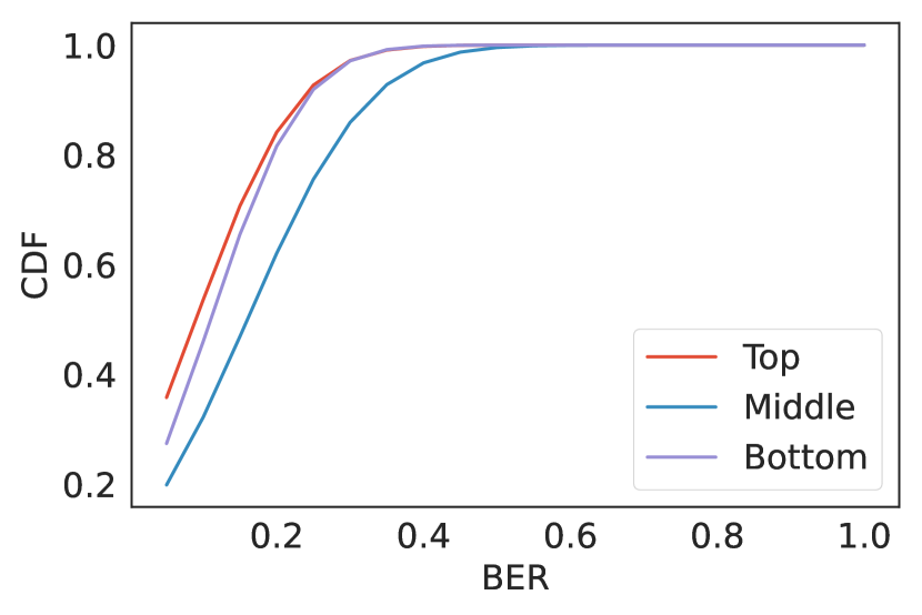
4.1. Effect of Distance Between Transmitter (Motor) and Receiver (Motion Sensor)
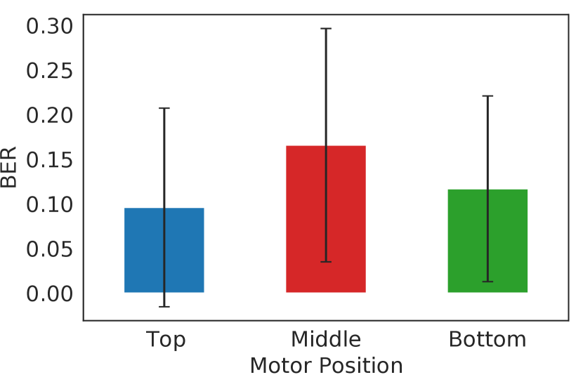
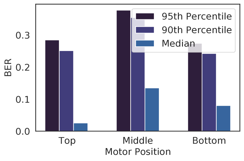
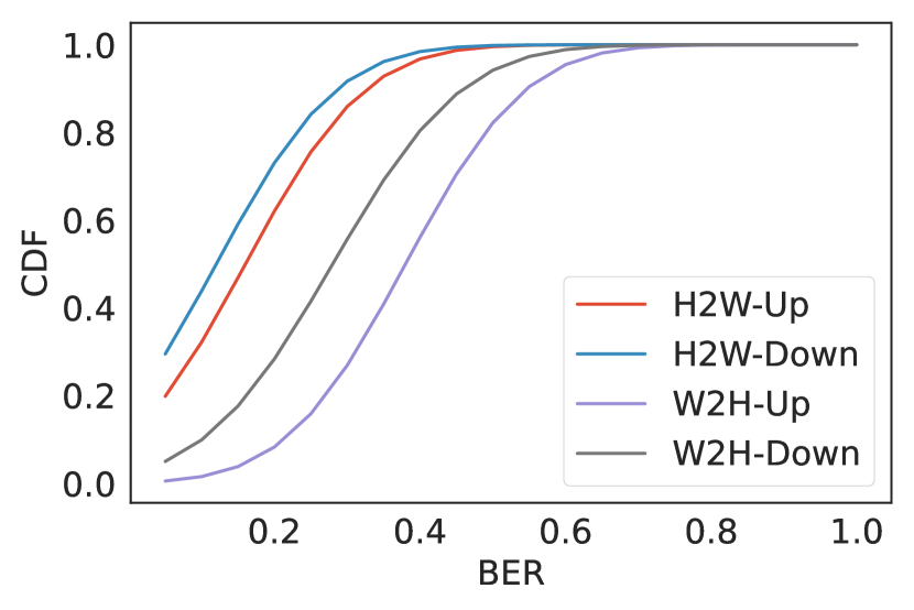
In order to observe the effect of distance between the transmitter (vibration motor) and receiver (accelerometer sensor) on system performance, we mount the motor on the phone case at three different positions. Specifically, the motor is mounted at the top, middle and bottom positions of the handheld device case, which results in a distance of approximately 15 cm, 7.5 cm, and 2 cm to the wrist wearable, respectively. We observe that when the motor is at the middle position, the performance slightly degrades (see Fig. 8(a)), while for top and bottom positions the resulting mean BERs are comparable. We further observe that in the middle motor position, for half the participants the resulting (BER) values are lower than 0.15 (see Fig. 8(b)) with five of them having BERs lower than 0.05. For the top (farthest from the receiver) motor position, we observe the best mean BER of 0.10 () and that half the number of participants have BERs lower than 0.05. In the bottom position, we have similar performance with a mean BER of 0.12 () and 50% of the participants with a BER less than 0.10. We observed that when the motor is positioned at the top of the handheld device, although farthest from the receiver (accelerometer), the vibrations makes the whole handheld device slightly more agitated. This, in turn, results in a stronger vibration signal reaching the accelerometer at the receiver. A similar effect is observed when the motor is mounted on the bottom of the handheld device. When the motor is mounted on the middle of the device, the vibrations are slightly dampened, accompanied by the fact that human palm is curved in the middle and thus the direct surface area that may be coming in contact with the hand when vibrating is smaller, which is reflected in the slightly higher BER values. From Fig. 8(f), which depicts the cumulative probability distribution of BER for each transmitter-receiver distance, we can see that for nearly 70% of the cases in the top and bottom positions, the achievable BER is less than 0.15.
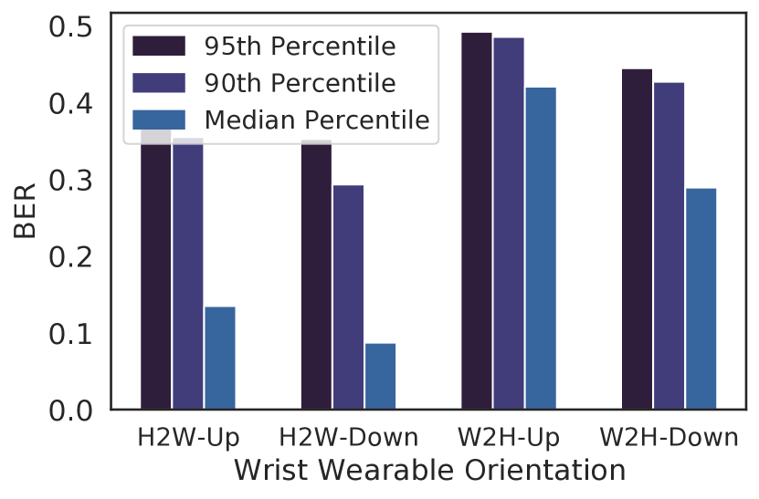
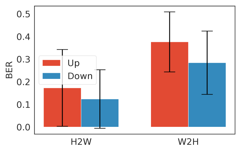
4.2. Effect of Wrist Wearable Orientation
Next we evaluate the effect of the wrist wearable’s orientation on system performance, with the communication direction from the handheld device to the wrist wearable (Fig. 7(b)). Here, we see (Fig. 8(e)) slightly lower BERs when the wrist wearable is worn facing downwards (accelerometer located at the bottom of the wrist) compared to when facing upwards (accelerometer located on the top of the wrist), with BER values of 0.12 () and 0.16 (), respectively. Fig. 8(c) shows that half the participants had BERs less than 0.10 for the face down orientation. We believe that this is because when the vibration motor and motion sensors are aligned on the same side of the hand, the vibrations have a more direct path to travel. Further, from Fig. 8(g), we see that for the face down orientation, close to 70% of the time BER will be lower than 0.2, as opposed to 60% probability in the face up orientation.
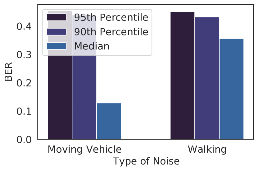
4.3. Performance Under Noise
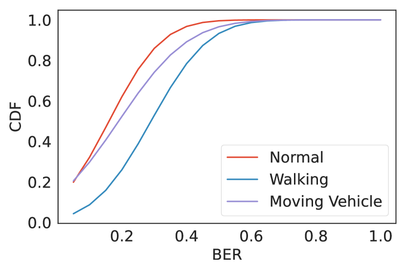
Next we evaluate SkinSense under two different types of movement noise that impact motion sensor readings. The first type of noise occurs when the user is relatively stationary while traveling inside a moving vehicle (with vehicle speeds between 16 to 64 ). Due to practical limitations, we simulated this experiment by superimposing prerecorded motion sensor data recorded from the handheld device while inside a moving vehicle, to the motion data collected from participants in a lab setting. The second type of noise we experimented with occurs due to user movement, where participants were asked to walk with the handheld device and wrist wearable on the same hand while SkinSense is executing. The first noise scenario (moving vehicle) shows slightly better performance with a mean BER of 0.19 (). Further, 7 out of the 13 participants showed BERs less than 0.10 (Fig. 8(c)), with only 3 participants showing significant degradation of BERs of over 0.3. This indicates that SkinSense is fairly robust against movement noise resulting from plane motion, such as traveling inside a vehicle. For the second type of noise scenario (walking), the BER considerably degrades with an observed mean BER of 0.29 (). For both the above scenarios, the communication direction was from the handheld to the wrist wearable. Moreover, with built-in APIs (Google, 2020) about user movements on modern mobile operating systems, such as Android and iOS/watchOS, it is also possible to contextually turn off SkinSense when the user is not stationary.
4.4. Effect of Sampling Rates
To evaluate the impact of reduced motion sensor sampling rates on protocol performance, we test SkinSense with the accelerometer (at the receiver) sampled at 200 Hz, compared to the 700 Hz sampling rate which was used previously. We choose a sampling rate of 200 Hz because it is the maximum sampling rate that is achievable on most modern consumer level mobile and wearable devices. Based on the results obtained in this setting, we observe that the BER of the communication scheme degrades to around 0.4 () when a lower sampling rate is used. This indicates that such a low accelerometer sampling rate at the receiver is probably not sufficient for capturing the range of vibration frequencies that we are utilizing to encode data in our transmission algorithm. With the limitation of not being able to use multiple frequencies, achieving a better BER would only be possible at the cost of a reduced bit rate.
4.5. Half-Duplex Communications
In the experimental settings discussed so far, we have only considered communication in the direction from the handheld device to the wrist wearable. However, as modern wearable and handheld devices come equipped with both a vibration motor and motion sensors, it would be extremely useful to evaluate communication in the reverse direction to what we have evaluated so far (i.e., from the wrist wearable to the handheld, in our case). If feasible, it would grant a half-duplex property to the communication channel, which would enable a whole set of applications that require communication in both directions. As our proposed communication protocol and hardware setup is amenable to such an evaluation, we also test communications in the reverse direction, i.e. using the wrist wearable as a transmitter and the handheld device as a receiver. Overall, the achieved performance results are significantly lower compared to the earlier case, as seen in the Fig. 8(e) and Fig. 8(c) with overall BERs dropping to 0.38 () for when wrist wearable is facing upwards and 0.28 () for when the wrist wearable is facing downwards. Similar to the wrist wearable orientation experiment (Section 4.2), we observe that when the wrist wearable is facing downwards a lower BER can be achieved. We also conduct the same noise-related experiments (similar to Section 4.3) for this setting and observe a similar pattern in the performance results where the user movement (walking) experiment degraded the BER to 0.43 () while the vehicle movement experiment reduced it to 0.42 (). These low performance results can be attributed to the fact that the wrist wearable surface area in contact with the wrist/hand is much smaller compared to the handheld device. This may result in reduced perception of the generated vibrations by the the skin/hand, thus resulting in an overall reduced performance.
4.6. Consumer-grade Hardware Setup
Next we discuss the performance of SkinSense when using commercial consumer-grade hardware (as summarized in Section 3.4.2). With the highly constrained access to the vibration motor and motion sensors on commercial mobile and wearable devices, SkinSense when executed on these devices could only achieve low overall BERs of around 0.4, for both the watch wearing orientations. We believe that one of the main constraints is the software-restricted sampling rates of motion sensors in commercial smartphones/smartwatches, which limits the maximum allowable sampling rate to only 200 Hz. Further, the Android API also restricts the frequency modulation of the vibration motor on these devices, which prevents us from using the embedded motor at its full operating capacity. These factors restrict us from using the 4 PWM frequency bands (of the motor) for communication which we used in the custom hardware case. As a result, we are not able to modulate in the PWM frequency band in the commercial device case, which effectively brings down the achievable bit rate from 6.6 to 3.3 bps. Although the reduced performance of SkinSense can be primarily attributed to the software and hardware limitations of existing commercially-available mobile device hardware, we believe that better motion sensors (with high sensitivity and sampling rates) and vibration motors in future devices will result in a slightly more favorable outcome for such vibration-based communication systems.
4.7. Accelerometer vs. Gyroscope
Our preliminary experiments involving both the custom and consumer-grade devices demonstrated that accelerometers produced better feedback than gyroscopes in our setup. To comprehensively compare the impact on performance when a gyroscope is used as a receiver as opposed to an accelerometer, we perform some additional experiments using our custom hardware setup. Based on the observed results (see Table 1), we can conclude that our protocol produces better performance (lower BER) using the accelerometer. The achievable BER drops from 0.16 to 0.39 when a gyroscope is used as a receiver (when transmitting from the handheld device). In contrast to accelerometers, gyroscopes measure a device’s angular velocity and it is likely that surface vibrations, which are already dampened down as they travel through the human skin/body, do not produce a significant amount of angular motion to be discernible on a gyroscope.
Direction Accelerometer Gyroscope Handheld to wrist wearable 0.16 () 0.39 () Wrist wearable to handheld 0.38 () 0.41 ()
4.8. Failed Transmission Detection
After further scrutinizing the transmitted messages with higher BERs, we observed that these inaccuracies are mostly caused due to missing bits, which may be due to voluntary or involuntary hand movements occurring during data transmission. To overcome this, we propose a message length based verification at the receiver. For this, if we assume that the receiver knows the length of the incoming message, or that the message length is fixed. Incorrectly or erroneously received messages can be easily identified (and flagged) based on bit length mismatches. In case of such a mismatch detection, the receiver can request a re-transmission. We observe that using such a heuristic significantly improves the BERs in our custom hardware setup, where BERs dropped below 0.04 when erroneously received messages are correctly identified for re-transmission.
4.9. In-Depth Analysis
4.9.1. Bit Rate vs Error Rate
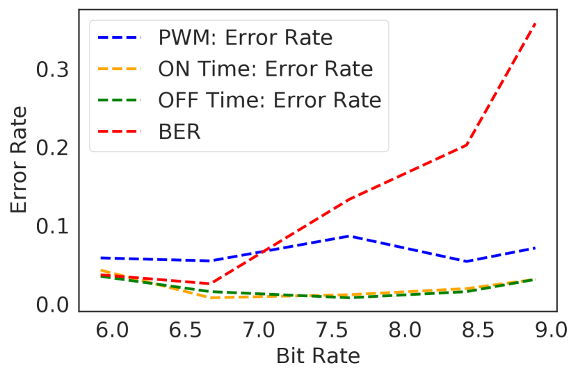
As discussed before, to gain higher transmission speeds we can reduce the ON times of the encoding algorithm, but this directly affects the accuracy which can be seen in Fig. 9(a). At higher bit rates, starting around 7 bps, BER steadily increases. However, we believe that with the use of more advanced, highly sensitive motion sensors that could be operated at higher sampling rates, SkinSense could achieve higher transmission speeds while maintaining a low error rate.
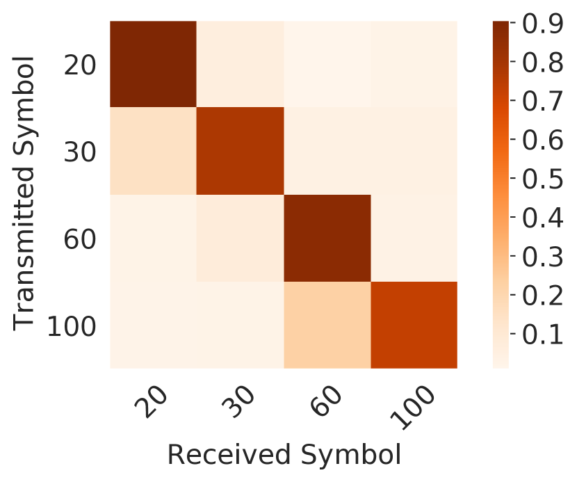
Fig. 10(a) shows the confusion matrix for PWM-based symbols, and we observe that most errors occur between adjacent PWMs (e.g. 20 and 30, or 60 and 100). As previously discussed in Section 3.2, we chose the PWMs to be 20, 30, 60, and 100 after observing that they have minimal confusion with each other when decoded via the accelerometer signal. However, when testing under realistic settings with possible variations in bone structure of hands of different users, along with variations in the way they hold a handheld device in their palm, we observed that some of these PWM-based frequency vibrations could get picked up by an accelerometer differently. Essentially, if we are able to use additional PWMs (i.e. vibration frequencies) as carriers to encode data, we would be able to achieve a higher bit rate. But due to the fact that accelerometer sensors are not able to distinctly identify some of the adjacent frequencies, it limits us from achieving a higher bit rate. In other words, higher bit rates would come at the cost of higher error rates (BERs). This is further confirmed by Roy et al. (Roy et al., 2015), who also highlighted in their work that high energy vibrations, occurring in the resonant frequency band, could potentially interfere with neighboring frequencies, which also limit the number of usable frequency bands in such vibration-based communication schemes.
4.9.2. Analysis of Individual Encoding Parameters
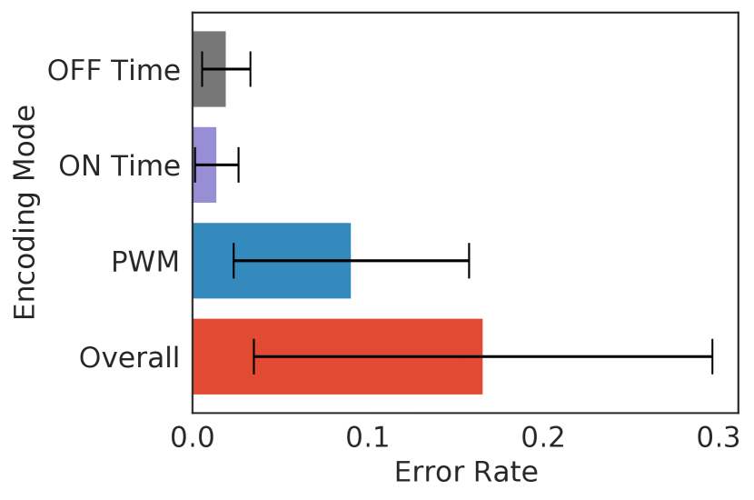
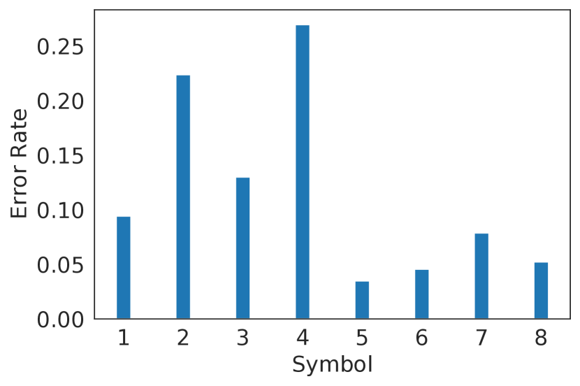
We also analyze each of the individual parameter modes in our algorithm which we use to encode data, i.e. PWMs, ON times and OFF times. We analyze the error rates of these modes individually to understand which modes work the best, in terms of bit rates or bit error rates. Fig. 9(b) shows individual error rates for each of these modes. We see that the time-based modes (ON and OFF) perform the best with overall error rates less than 0.02, while the frequency-based mode (PWMs) show a relatively higher error (0.10). Although the time-based modes work more reliably than the PWM, the amount of modulation that can be done using time-based modes would be limited due to them being directly affecting the bit rates/transmission speeds. Fig. 10(b) indicates the error rates for each individual symbol where numbers 1-4 are PWMs, 5 and 6 are ON times and 7 and 8 OFF times. This further shows that time-based symbols (5-8) perform the best as opposed to the PWM-based symbols. The observations made in Fig. 10(a) is further clarified here as it can be seen that PWMs 30 and 100 show the highest error rates due to them being misidentified as 20 and 60, respectively.
4.10. Acoustic Side-Channel
Roy et al. (Roy et al., 2015) recognized the possibility of information leakage via the noise produced during vibrations, and proposed a mechanism to jam the acoustic side-channel by emitting a noise from the transmitter to suppress the sound produced by vibrations. They further studied the sound of vibrations (SoV) for different surfaces that the transmitter may be placed upon, and observed that glass surfaces cause the highest side-channel leaks, i.e. produces the loudest noise. To understand the severity of such a vulnerability in our proposed system, we similarly measure the SoV when a hand is used as the communication medium. Table 2 provides the ratio of SoV of our custom and consumer-grade device setup (recorded 2 ft away from the transmitter) to the ambient noise at various locations including, a school laboratory, an apartment, inside a moving vehicle and in a supermarket. The lower the ratio (closer to zero), the quieter the SoV is relative to the ambient noise, thus, reducing the risk of acoustic leakage. We observe the SoV to ambient noise ratio to be high in quieter locations such as an apartment or a school lab, while the ratio falls below 1 for louder locations such as a vehicle or a supermarket. This is in contrast to Roy et al.’s (Roy et al., 2015) results, where the ratio was around 1.5 for all these locations. Compared to the consumer-grade smartphone setup, our custom setup (as seen in Table 2) produces much louder sound ratios, which is likely because of the vibration motor being mounted on the custom handheld device without an enclosure. The acoustic leakage from SkinSense is significantly lower when consumer-grade mobile devices are used due to the enclosed nature of the vibration motor in such devices. We believe that this threat can be minimized by employing an acoustic jamming mechanism similar to the one proposed by Roy et al. (Roy et al., 2015) by utilizing a speaker near the transmitting device.
Setup Lab Apartment Vehicle Supermarket Custom hardware setup 2.11 2.20 0.92 0.80 Consumer level smartphone 1.46 1.52 0.63 0.58
4.11. Practical Significance of the Bit Rate
To understand the practical usefulness of the bitrate afforded by SkinSense, we further analyze the transfer time for practical device-to-device secrets such as 4-digit PINs and 8-character passwords. For this analysis, we consider the data transfer scenario from the hand-held device to the wrist-wearable at a distance of 7.5 . We observe that transfer of a 4-digit PIN takes a little more than 5 seconds, while an 8-character password takes approximately 10 seconds. Although these transfer speeds are considerably slower compared to short-range radio technologies such as Bluetooth and NFC, it must be noted that SkinSense is envisioned to be only used as a potential secure side-channel to supplement traditional radio-based communication channels. Specifically as observed above, SkinSense can enable usage scenarios such as securely proving device co-location or secure authentication in the absence of reliable radio channels by enabling sharing of short secrets at reasonable side-channel speeds.
4.12. Energy Requirements
To evaluate the energy requirements of SkinSense, we conducted an experiment to measure the amount of battery energy consumed over time. For the transmitter, we tested on two smartphones by sending 30 messages over a period of 1 hour. For the receiver, we tested two smartwatches by running the motion sensor data collection for 30 messages over a period of 1 hour. As seen in Table 3, energy consumption is only around 150 for Moto G7 Plus (2019) which is a newer device with Android 10, compared to the 300 for an older smartphone, Nokia 6 (2016), with Android 9. The receiver smartwatches show a similar energy consumption pattern with the newer Ticwatch with only 12 consumption compared to 14 in the older Sony W3.
Device Battery Capacity Energy Consumed Sony W3 420 14 Mobovi Ticwatch E 300 12 Nokia 6 3000 300 Moto G7 Plus 3000 150
4.13. Comparison with Previous Works
Related Work Setting Sensors Technique Used Data Rate Performance VibeRing (Sen and Kotz, 2020) Ring on finger to device Accelerometer Machine Learning based 12.5 0.05 (BER) Ripple (Roy et al., 2015) 2 devices on a solid surface Accelerometer Frequency domain based 200 0.017 (BER) Vib-Connect (Yonezawa et al., 2011b) 2 devices in direct contact (mobile phone and laptop) Accelerometer Time domain thresholding based Not mentioned 100% (Accuracy) SYNCVIBE(Lee et al., 2018) 2 devices in direct contact Accelerometer Time domain based 20 0.005 (BER) SecureVibe(Kim et al., 2015) Device on top of a implanted medical device Accelerometer Time domain based 20 Not mentioned Skin Sense (this work) Between handheld device to wrist-wearable via skin Accelerometer Frequency & time domain domain based 6.6 0.10 (BER)
Sen and Kotz (Sen and Kotz, 2020) proposed a vibration-based communication scheme using a smart ring, where the smart ring act as the vibration transmitter to communicate with Internet-of-Things (IoT) devices embedded with accelerometers. They were able to achieve a BER of 0.05 with a bandwidth of 12.5 . Similar to many of the above mentioned works, their smart ring transmitter was required to be in direct contact with the receiver IoT device for reliable communication. The closest work to ours, in terms of using the human body/skin as the communication medium, is by Ma et al. (Ma et al., 2020). They proposed a Multiple-Input-Multiple-Output (MIMO) communication scheme using two vibration motors and two piezo transducers. Due to limitations of vibration motors such as ramping time and the volatile nature of human skin as a channel, they use two motion sensors (acceleromter+gyroscope) embedded at the transmitter side, in order to acquire and utilize additional Channel State Information (CSI) by employing deep learning. Their MIMO scheme was able to achieve a MIMO capacity of about 5 , which is more than twice the capacity that could be achieved using a comparable Single-Input-Single-Output setup. However, there are several drawbacks in their proposal. First, their scheme is not very practical because it relies on extremely customized hardware and setup, often not found in commercial mobile and IoT devices. Moreover, their scheme employs deep learning algorithms that typically require large amounts of training data for acceptable performance, which may not be trivial to obtain for all communication settings, conditions, and individual users. Lastly, performance evaluation of their scheme was done using data from only two human subject participants, and so it is unclear how generalizable their results are. Another similar work (SecureVibe) which uses skin as a medium was proposed by Kim et al. (Kim et al., 2015) using a smartphone vibration motor and a custom made implantable medical device equipped with an accelerometer. Although, their work achieves bit rates around 20 , their setup requires the smartphone to be directly on top of the implanted device under the skin with only 1 distance between the motion sensor and the smartphone. We demonstrate that SkinSense framework could be effective up to a distance of 15 between the handheld smartphone (vibration motor) and the wrist wearable (motion sensor). Further, their work was only evaluated using an emulated human body model and not on actual human subject participants. In contrast, SkinSense is proposed for two externally held/worn devices, and the communication protocol was tested with human subject participants. Shah et al. specifically studied the vibration propagation via skin of human arm and reported that even at a mere distance of 4 (Shah et al., 2019), the vibration intensity drops around 70-80% and continues to drop over 90% at distances over 8 . In contrast, in a rigid medium such as a wooden board, the authors of Ripple (Roy et al., 2015), observe that vibration intensity gradually increases up to 15 before attenuating. This allows them to use 10 different vibration amplitudes to transmit data and still be able to accurately distinguish them during the demodulation to achieve a relatively higher data rate of 200 . It should be noted that on a medium with low rigidity such as the human skin, propagation of the vibration signal attenuates much more quickly at longer distances. This makes SkinSense’s design challenge a rather non-trivial one and with the same token makes adaptation of techniques employed by protocols such as Ripple (Roy et al., 2015) in this scenario infeasible.
5. Discussion
User’s Perception and Preferences. As vibrations carried by the human skin/body is perceptible to the end-user, we deployed a short survey to our 13 participants to gauge their feelings about the SkinSense protocol. Based on the received survey responses, 38% of the participants noted that they were not bothered by SkinSense’s operation, while 54% were bothered slightly and only 8% were highly bothered. Although users can take advantage of SkinSense by easily switching (or transfering) the hand-held device to the wrist-wearable device hand, we also studied users’ preferences regarding SkinSense usage. When asked about which hand they use to hold a handheld device/smartphone, around 62% answered that they use the same hand as the wrist wearable wearing hand followed by 23% who use both the hands. The remaining 15% said that they use their non-smartphone holding hand to wear the wrist wearable. Findings of this short survey does indicate that a vibration-based communication protocol such as SkinSense is usable (from an end-user perspective) in practice, although more extensive usability and user-satisfaction surveys are needed.
Other Side-channels. In addition to the acoustic side-channel threat, there is a possibility of an attacker physically attaching an eavesdropping motion sensor to the communication surface (Roy et al., 2015). We believe that such a type of threat is unlikely in our proposed communication setup/protocol because we use the human body/skin as the communication channel. An adversary is unlikely to be able to directly attach an eavesdropping device to a victim user’s body/skin without their cognizance. The transmitted messages could also be encrypted to further minimize the possibility of a contact based attack. Further from the security perspective, as SkinSense’s main goal is to provide a secure channel against external eavesdropping devices, we assume that both the transmitter and receiver devices are fully trusted, executing only trusted (or non-malicious) apps.
6. Related Works
Vibration-based communication techniques that employ vibration motors and motion sensors (esp. accelerometers) have been previously studied for various forms of underlying communication mediums (or channels), such as hard surfaces, direct device-to-device contact, and also via human skin. Yonezawa et al. (Yonezawa et al., 2011a, b) proposed a mechanism to send information from a smartphone to a laptop computer and achieved a data rate up to 10 . Their proposal encodes information in a vibration signal emitted by the smartphone, which needs to be kept in physical contact of the laptop, and the laptop detects the vibrations (with the encoded information) via an embedded or on-board accelerometer. Lee et al. (Lee et al., 2018) proposed a similar communication framework (SYNCVIBE) where the 2 devices require physical contact using a smartphone as a vibration transmitter and an external accelerometer device as a receiver attached to it and were able to achieve data rates around 20 with a BER of 0.005. Hwang et al. (Hwang et al., 2012) proposed a similar communication mechanism, but between two smartphones placed on a solid surface, such as a wooden table, metal or plastic shelf, a stack of paper, and a cushioned chair. Their scheme achieved over 90% accuracy for all the surfaces when the devices are placed roughly 25 from each other. However, the accuracy drops significantly when the two devices are too close (10 ) or too far apart.
Roy et al. (Roy et al., 2015) proposed a similar communication framework, named Ripple, which achieved a data rate of up to 200 by using custom off-the-shelf vibration motors and accelerometer chips, and up to 80 by using consumer smartphones. However, like Hwang et al. (Hwang et al., 2012), they employed solid surfaces such as wooden and glass tables as the communication medium (or channel) in their scheme. In a follow-up effort, Roy et al. (Roy and Choudhury, 2016) proposed another vibration-based communication technique, but this time by using a microphone instead of an accelerometer as the receiver. Evaluation of their follow-up proposal showed that a smart ring with a vibration motor can achieve a bandwidth or data rate of around 7 , while for a smartwatch the bandwidth drops to 2 . However, an important requirement of their scheme was that the transmitting device had to be in close proximity to the microphone-based receiver to achieve these bandwidths.
7. Conclusion
In this paper we explored a novel form of communication between a handheld device and a wrist wearable by using a vibration motor transmitter and accelerometer-based receiver with human skin/hand being used as the communication medium. Since the human hand could have various anatomical and biomechanical differences among different people, we tested our proposed scheme under multiple realistic settings with 13 human subjects. Our proposed scheme was able to achieve a sustainable bandwidth of 6.66 bps while keeping the BER below 0.10. Although, the current consumer level smartphones and wrist wearables have limitations, resulting in our scheme not being able to perform optimally, we believe that our work opens up further research in the area related to vibrations and human body-area communication channels.
References
- (1)
- Ali and Liu (2021) Kamran Ali and Alex X Liu. 2021. Fine-grained Vibration Based Sensing Using a Smartphone. IEEE Transactions on Mobile Computing (2021).
- Bannis et al. (2020) Adeola Bannis, Hae Young Noh, and Pei Zhang. 2020. Bleep: motor-enabled audio side-channel for constrained UAVs. In Proceedings of ACM MobiCom’20.
- Barr (2001) Michael Barr. 2001. Pulse width modulation. Embedded Systems Programming 14, 10 (2001), 103–104.
- Blake (1961) Ralph E Blake. 1961. Basic vibration theory. Shock and vibration handbook 1 (1961), 2–8.
- Bloothooft et al. (1992) Gerrit Bloothooft, Eldrid Bringmann, Marieke Van Cappellen, Jolanda B Van Luipen, and Koen P Thomassen. 1992. Acoustics and perception of overtone singing. The Journal of the Acoustical Society of America 92, 4 (1992), 1827–1836.
- Chevalier et al. (2015a) Ludovic Chevalier, Stephanie Sahuguede, and Anne Julien-Vergonjanne. 2015a. Optical wireless links as an alternative to radio-frequency for medical body area networks. IEEE Journal on Selected Areas in Communications (2015).
- Chevalier et al. (2015b) Ludovic Chevalier, Stéphanie Sahuguede, and Anne Julien-Vergonjanne. 2015b. Wireless optical technology based body area network for health monitoring application. In Proceedings of IEEE ICC’15.
- Components101 (2020) Components101. 2020. L298N Motor Driver Module. https://components101.com/modules/l293n-motor-driver-module [Online; accessed 15-Nov-2021].
- D’Alessandro et al. (2019) Antonino D’Alessandro, Salvatore Scudero, and Giovanni Vitale. 2019. A review of the capacitive MEMS for seismology. Sensors 19, 14 (2019), 3093.
- Galluccio et al. (2012) Laura Galluccio, Tommaso Melodia, Sergio Palazzo, and Giuseppe Enrico Santagati. 2012. Challenges and implications of using ultrasonic communications in intra-body area networks. In Proceedings of IEEE WONS’12.
- Gao and Zhang (2004) Robert Gao and Li Zhang. 2004. Micromachined microsensors for manufacturing. IEEE Instrumentation & Measurement Magazine 7, 2 (2004), 20–26.
- Gao et al. (2021) Shuo Gao, Shuo Yan, Hang Zhao, and Arokia Nathan. 2021. Touch-Based Human-Machine Interaction: Principles and Applications. 91–108.
- Google (2020) Google. 2020. Step detector sensor. https://developer.android.com/reference/android/hardware/Sensor#TYPE_STEP_DETECTOR [Online; accessed 15-Nov-2021].
- Huang et al. (2016) Huaiqi Huang, Tao Li, Christian Antfolk, Christian Enz, Jörn Justiz, and Volker M Koch. 2016. Experiment and investigation of two types of vibrotactile devices. In Proceedings of IEEE BioRob’16.
- Hwang et al. (2012) Inhwan Hwang, Jungchan Cho, and Songhwai Oh. 2012. Privacy-aware communication for smartphones using vibration. In Proceedings of IEEE RTCSA’12.
- Kim et al. (2015) Younghyun Kim, Woo Suk Lee, Vijay Raghunathan, Niraj K Jha, and Anand Raghunathan. 2015. Vibration-based secure side channel for medical devices. In Proceedings of ACM/EDAC/IEEE DAC’15.
- Laput et al. (2016) Gierad Laput, Robert Xiao, and Chris Harrison. 2016. Viband: High-fidelity bio-acoustic sensing using commodity smartwatch accelerometers. In Proceedings of ACM UIST’16.
- Lee et al. (2018) Kyuin Lee, Vijay Raghunathan, Anand Raghunathan, and Younghyun Kim. 2018. SYNCVIBE: Fast and secure device pairing through physical vibration on commodity smartphones. In Proceedings of IEEE ICCD’18.
- Luo et al. (2018) Pengfei Luo, Tong Jiang, Paul Anthony Haigh, Zabih Ghassemlooy, and Stanislav Zvanovec. 2018. Undersampled pulse width modulation for optical camera communications. In Proceedings of IEEE ICC Workshops.
- Ma et al. (2020) Dong Ma, Yuezhong Wu, Ming Ding, Mahbub Hassan, and Wen Hu. 2020. Skin-MIMO: Vibration-based MIMO Communication over Human Skin. In Proceedings of IEEE INFOCOM’20.
- Manfredi et al. (2012) Louise R Manfredi, Andrew T Baker, Damian O Elias, John F Dammann III, Mark C Zielinski, Vicky S Polashock, and Sliman J Bensmaia. 2012. The effect of surface wave propagation on neural responses to vibration in primate glabrous skin. PLOS ONE 7, 2 (2012).
- Michalevsky et al. (2014) Yan Michalevsky, Dan Boneh, and Gabi Nakibly. 2014. Gyrophone: Recognizing speech from gyroscope signals. In Proceedings of USENIX SECURITY’14.
- Ramesh et al. (2019) Soundarya Ramesh, Thomas Pathier, and Jun Han. 2019. Sounduav: Towards delivery drone authentication via acoustic noise fingerprinting. In Proceedings of the 5th Workshop on Micro Aerial Vehicle Networks, Systems, and Applications.
- Rittweger (2020) Jörn Rittweger. 2020. Manual of Vibration Exercise and Vibration Therapy. Springer.
- Roy and Choudhury (2016) Nirupam Roy and Romit Roy Choudhury. 2016. Ripple II: Faster communication through physical vibration. In Proceedings of USENIX NSDI’16.
- Roy et al. (2015) Nirupam Roy, Mahanth Gowda, and Romit Roy Choudhury. 2015. Ripple: Communicating through physical vibration. In Proceedings of USENIX NSDI’15.
- Rushanan et al. (2014) Michael Rushanan, Aviel D Rubin, Denis Foo Kune, and Colleen M Swanson. 2014. Sok: Security and privacy in implantable medical devices and body area networks. In Proceedings of IEEE S&P’14.
- Seim et al. (2015) Caitlyn Seim, James Hallam, Shashank Raghu, Tri-An Le, Greg Bishop, and Thad Starner. 2015. Perception in hand-worn haptics: Placement, simultaneous stimuli, and vibration motor comparisons. Technical Report. Georgia Institute of Technology.
- Sen and Kotz (2020) Sougata Sen and David Kotz. 2020. VibeRing: Using vibrations from a smart ring as an out-of-band channel for sharing secret keys. In Proceedings of IEEE IoT’20.
- Shah et al. (2019) Valay A Shah, Maura Casadio, Robert A Scheidt, and Leigh A Mrotek. 2019. Vibration Propagation on the Skin of the Arm. Applied Sciences 9, 20 (2019), 4329.
- Shoaib et al. (2016) Muhammad Shoaib, Stephan Bosch, Ozlem Durmaz Incel, Hans Scholten, and Paul JM Havinga. 2016. Complex human activity recognition using smartphone and wrist-worn motion sensors. Sensors 16, 4 (2016), 426.
- Varanis et al. (2018) Marcus Varanis, Anderson Silva, Arthur Mereles, and Robson Pederiva. 2018. MEMS accelerometers for mechanical vibrations analysis: A comprehensive review with applications. Journal of the Brazilian Society of Mechanical Sciences and Engineering 40, 11 (2018), 1–18.
- Venkatanarayanan and Spain (2014) Anita Venkatanarayanan and Elaine Spain. 2014. 13.03 - Review of Recent Developments in Sensing Materials. In Comprehensive Materials Processing. Elsevier, 47–101.
- Yonezawa et al. (2011a) Takuro Yonezawa, Tomotaka Ito, and Hideyuki Tokuda. 2011a. Transferring information from mobile devices to personal computers by using vibration and accelerometer. In Proceedings of ACM UbiComp’11.
- Yonezawa et al. (2011b) Takuro Yonezawa, Hiroshi Nakahara, and Hideyuki Tokuda. 2011b. Vib-connect: A device collaboration interface using vibration. In Proceedings of IEEE RTCSA’11.