Magnetic order in nanoscale gyroid networks
Abstract
Three-dimensional magnetic metamaterials feature interesting phenomena that arise from a delicate interplay of material properties, local anisotropy, curvature, and connectivity. A particularly interesting magnetic lattice that combines these aspects is that of nanoscale gyroids, with a highly-interconnected chiral network with local three-connectivity reminiscent of three-dimensional artificial spin ices. Here, we use finite-element micromagnetic simulations to elucidate the anisotropic behaviour of nanoscale nickel gyroid networks at applied fields and at remanence. We simplify the description of the micromagnetic spin states with a macrospin model to explain the anistropic global response, to quantify the extent of ice-like correlations, and to discuss qualitative features of the anisotropic magnetoresistance in the three-dimensional network. Our results demonstrate the large variability of the magnetic order in extended gyroid networks, which might enable future spintronic functionalities, including neuromorphic computing and non-reciprocal transport.
Networks of interacting nanomagnetic wires offer insight into emergent phenomena and functionalities arising from the underlying geometrical design and local connectivity. A well-studied class of these networks are two-dimensional artificial spin ices (ASI) and magnonic crystals [1, 2, 3], which allowed the observation via imaging or magnetotransport of ice-like low-energy states [4, 5, 6] and monopole-like excitations [7, 8]. Because of the stochastic behaviour and large reconfigurability of interacting interconnected lattices, such magnetic metamaterials have also been proposed to be used for neuromorphic-inspired unconventional computational tasks [9, 10, 11].
Extending the study of emergent magnetic phenomena from planar two-dimensional to three-dimensional lattices promises novel functionalities [12, 13], related to magnetochiral effects in curvilinear geometries [14, 15, 16], fast magnetisation dynamics [17, 18, 19, 20], and network topologies with dense connections to distant neighbours [21, 22, 23]. Notable examples of magnetic three-dimensional networks studied so far include inverse opals [24, 25, 26], magnetic buckyballs [27, 18], and single-diamond lattices [21, 17]. In these studies, the connecting struts are usually several long and thus much larger than typical magnetic length scales, weakening possible curvilinear magnetic effects expected in truly nanoscale 3D networks.
Gyroid structures grown by polymer self-assembly feature a highly interconnected three-dimensional network, a global chiral structure and a lattice periodicity in the order of a few tens of nanometres. Recent studies on photonic gyroids demonstrated selective reflection of circularly polarised light [28] and the emergence of Weyl points [29, 30, 31]. With respect to magnetism, the local curvature of the gyroid is large enough to support a sizeable geometrical Dyzaloshinskii-Moriya interaction [14, 15] and its inherent chirality can give rise to emergent non-reciprocal effects [32, 33, 34], such as electrical magneto-chiral anisotropy [35, 36]. In our previous work [37], we imaged magnetic states of nanoscale gyroids using electron holography and observed complex magnetic states. However, the local spin anisotropy has not been elucidated and therefore possible ice-like correlations in magnetic gyroids have not yet been quantified so far.
Here, we use finite-element micromagnetic simulations to show that the field-driven and relaxed spin configurations of nanoscale nickel gyroids feature complex magnetic states arising from the non-trivial local anisotropy and the three-connectivity of the gyroid lattice, including the emergence of spin chiral effects. We discuss how the description of local spin order can be simplified using a macrospin model. We furthermore illustrate how the anisotropic magnetoresistance in finite-size gyroid networks, which, due to the inherently non-coplanar spin configuration as well as the 3D network connectivity, shows distinct behaviour compared to the response of bulk or planar devices. Our results underline the complexity of magnetic order in nanoscale 3D gyroids with inherently non-coplanar and frustrated spin order. These properties make gyroid networks ideal candidates for future studies of non-reciprocal effects or as platform for probabilistic and neuromorphic computing schemes.
I The gyroid geometry
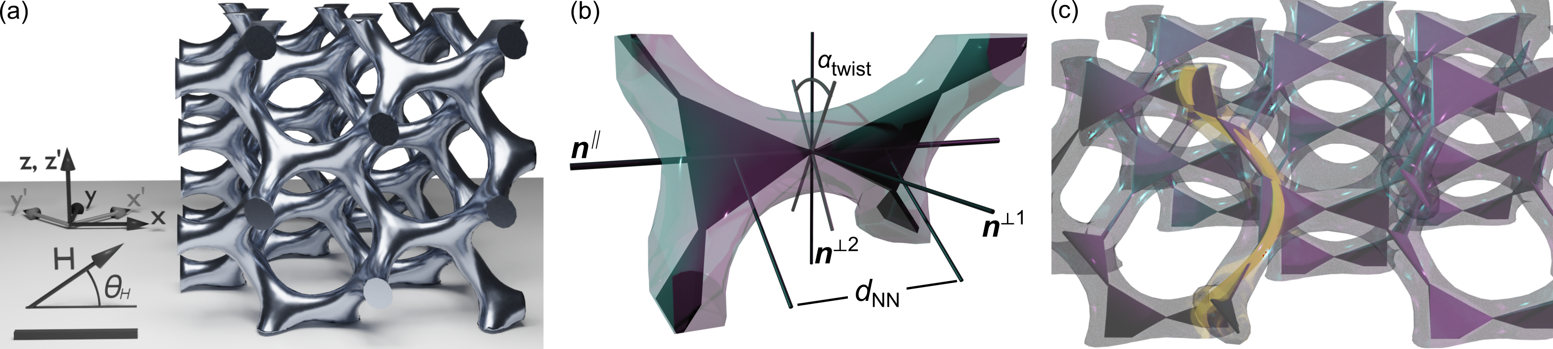
A single gyroid shown in Fig. 1(a), derived from the Schoen G triply-periodic minimal surface [38], is a 3D periodic network of connected struts which form chiral triple junctions. While gyroid photonic crystals are found in nature in the wings of some butterflies [39, 40], nanoscale gyroids with lattice periodicities in the range of to can be grown with large structural coherence over a few hundred micrometres by self-assembly of di- and tri-block co-polymer templates [41, 42, 43]. Selective etching followed by metal electrodeposition into the remaining scaffold results in single-gyroid network nanostructures with volume fill fractions between 10% and 30% [44].
Many of the interesting physical phenomena in gyroids are related to its inherent chirality, described by the cubic-centered space group I4132 (which allows for uniquely left- or right-handed gyroid structures), and the connectivity, mathematically also described as the srs net or K4 crystal [45, 46]. Vertices are connected to their neighbours by struts of length , with being the cubic lattice constant. Each cubic unit cell contains eight individual vertices and 18 struts. For each of the six strut directions, a local coordinate system can be defined as shown in Fig. 1(b) and summarised in Tab. 1, with denoting the main strut direction and neighbouring triangle planes rotated by .
Due to its underlying three-connectivity, the gyroid network can also be represented by corner-sharing triangles, as shown in Fig. 1(c), reminiscent of geometrically-frustrated magnetic systems that promote complex spin states, zero-temperature entropy and other interesting emergent properties like magnetic monopoles [47, 48, 49]. Furthermore, a multitude of possible paths through the network exist. These include gyrating channels, such as the one highlighted yellow in Fig. 1(c) corresponding to the tightest possible helix path through the gyroid with radius and periodicity .
| strut | |||
|---|---|---|---|
| 1 | |||
| 2 | |||
| 3 | |||
| 4 | |||
| 5 | |||
| 6 |
II Micromagnetic Simulations
Inspired by single-gyroids networks grown by self-assembly and studied by electron holography [37], in this work we focus on gyroids with a cubic lattice constant and a volume fraction of . We use a coordinate system () rotated by around the direction (with cubic crystallographic coordinates ), as polymer gyroid templates yield preferential growth along the direction.
We performed finite-element micromagnetic simulations to study the magnetic-field-driven response of a nickel gyroid structure, using the software finmag [50]. Magnetic properties of nickel were described by a saturation magnetisation and an exchange constant . We assumed vanishing magnetocrystalline anisotropy, i.e., . The mesh of this gyroid simulation cell with a volume of , i.e., , as shown in Fig. 1(a), was generated using COMSOL Multiphysics® [51] and contained 18196 nodes with a mean edge distance of (i.e., smaller than the magnetostatic exchange length .
For applied magnetic fields , equivalent to in-plane fields for gyroids grown by self-assembly, and a randomised initial spin configuration, micromagnetic configurations were obtained after relaxation. The external field was then switched off, , and the spin configuration again relaxed to obtain states at remanence. This process was repeated for angles between and in increments, and at field magnitudes , and .
Analysis of the collective response was performed using the python package networkx [52] by associating the local macrospins of the gyroid structure with the edges of the underlying srs network. This allowed to calculate properties such as the scalar spin chirality , local ice rules , as well as the anisotropic magnetoresistance as network resistance between specified nodes.
III Results and Discussion
In the following, we will first discuss the global field-driven response of a single-gyroid structure, followed by assessing the local anisotropy of the individual struts to justify a macrospin picture of the gyroid network. We then turn to collective properties such as the magnetic order emerging on the triangular plaquettes and the global response from current transport through the network.
III.1 Global Response

From the field- and field-angle-dependent micromagnetic simulation, we obtain the magnetisation profile of the gyroid structure. Figure 2 shows the relation between the field angle in the plane (with for ) and both the average magnetisation magnitude and direction defined by
| (1) | |||||
| (2) |
At high magnetic fields of (solid gray line and gray squares) the sample magnetisation follows that of the applied field, i.e., , indicating that the structure is saturated. In contrast, at fields of the sample shows a slightly non-isotropic response [dashed blue line in Fig. 2(a)]. Configurations relaxed from (dashed red line and red circles) and (not shown) are qualitatively similar. They feature a reduced net moment and the magnetisation direction exhibits four distinct plateaus. The step-like reorientations occur around angles and , marked by vertical dashed lines in Fig. 2, with angles in the plane perpendicular to some of the struts. The anisotropic global response and prominent demagnetisation therefore indicate that the gyroid network plays a major role to the hysteretic behaviour.
The response at and the obtained remanent state indicate unsystematic minor magnetic loops, and thus are excluded from the following discussion.
III.2 Testing the Macrospin Assumption


The simplest model to describe the magnetic order of a gyroid network would be an Ising system: As shown in Fig. 2(a), the idea is to average the moments in each strut to a macrospin , and that the shape anisotropy forces this macrospin to be parallel to the local strut direction . With this Ising macrospin assumption, values of and at remanence can be predicted at specific field angles by averaging over the six strut directions (Tab. 1), as shown by black crosses in Fig. 2. For the moment direction in Fig. 2(b), the Ising macrospin picture yields at at , and or at , in reasonably good agreement with the micromagnetic simulation results.
The reasonable similarity between global and Ising-like behaviour justifies a closer look on the local anisotropies of the strut magnetisation: We obtain the magnitude and direction of strut macrospins as the average of the local moment within non-overlapping spherical volumes centred on each strut position , as shown in Fig. 3(a):
| (3) |
With radius the integration volumes contain about mesh points. Using this approach we simplify the full micromagnetic configuration with 18196 mesh nodes to 192 individual struts. We furthermore discard struts at the boundary of the simulation volume, and in the following consider the properties of 160 struts for each field magnitude and angle.
As shown in Fig. 3(b), at remanence the strut moments do indeed behave like macrospins, albeit not with the expected Ising-like anisotropy: Here, we separate the each strut moment into parallel and perpendicular components with respect to the local main strut direction : . Using this decomposition, in Fig. 3(b) we see that the net amplitude (blue dots) is close to one (black line), indicating a locally saturated magnetisation, with a reduction of at most 3%. Therefore, we can conclude that the macrospin assumption holds well, which is not entirely surprising: Each strut has a volume corresponding to a cylinder with diameter and length, dimensions which are comparable to the exchange length and thus supporting quasi-uniform strut magnetisation without the formation of domain walls.
III.3 Local Magnetic Anisotropy
Even though the struts’ behaviour can be approximated with quasi-uniform macrospins, the local anisotropy does not favour simple Ising-like behaviour. This is illustrated by the rose diagram in Fig. 3(b) (purple bars) which indicates that the macrospins have a median inclination of about to the main strut axis . Further insight to the local anisotropy can be gained by considering the spherical angles and denoting the macrospin orientation with respect to the local coordinate system defined in Tab. 1:
| (4) | |||||
| (5) |
As shown in Fig. 3(c), 90% of the moments fall into the area outlined by the dashed purple line. This permissible angular range, describing preferential anisotropy, combines ”wings” centred at and with and with a ”ring” in the – plane (, ). Here, the angle is the maximum spin canting due to geometrical DMI [15] predicted for the tightest possible helix path [yellow line in Fig. 1(c)].
The peculiar non-Ising, non-Heisenberg anisotropy is a direct consequence of at least three effects: (1) The wings in the anisotropy directly originates from the connectedness between vertices and the dominant exchange interaction which enforces magnetic continuity. As shown in Fig. 1(b), neighbouring triangular plaquettes are non-coplanar, therefore tilting of the moment away from can be energetically favourable to minimise the dipolar interactions between the net moments of the two vertices. However, tilting towards by more than leads to energy-costly magnetic charges. (2) The ring corrresponds to small spin canting up to maximum values due to geometrical DMI, showing a small asymmetry for fields at and . (3) Slight asymmetries in the average angles of macrospins at and indicate a chiral contribution to the magnetic anisotropy, likely related to the underlying chiral right-handed crystal structure.
III.4 Hysteretic Behaviour
Figure 4 gives further insight to the relationship between local anisotropy and hysteretic behaviour, broken down for individual struts : Here, the local macrospin moments are indicated by black points, projected onto the corresponding coordinate system , , and . Coloured arrows indicate the mean moment direction at a given field angle , averaged over all equivalent struts.
Figure 4(a) shows the behaviour at applied fields of . As the field angle is defined in the global -plane, the struts are differently oriented with respect to the simulation coordinate frame. Therefore, the same field pulls the strut moments in significantly different directions with respect to the local coordinate system. A field magnitude of does not yet fully saturate the gyroid magnetisation, and the effect of local anisotropy is evident by the non-uniform rotation of the moment with the field direction.
Figure 4(b) shows the equivalent moment configurations at remanence relaxed from . The high-field state clearly influences the final configuration, and generally, four specific low-energy moment configurations can be classified for each strut, in accordance with the four plateaus of global magnetisation direction shown in Fig. 2 (red circles). The complex response of the local macrospins in combination with the highly-connected network therefore lead to emergent collective order in extended gyroid networks.
III.5 Spin Ice Rules

To discuss possible collective effects in the gyroid network, we first will focus on the statistical properties and magnetic connectivity of the corner-sharing triangular plaquettes, as shown in Fig. 1(c). In many cases, the spin order of frustrated magnetic networks with triangular plaquettes is governed by local ice rules instead of long-ranged global order [48, 49, 4, 5, 6]. To discuss the concept of ice rules in the gyroid network, in the following we will consider the scalar Ising-like component of the strut macrospin defined by
| (6) |
Here, denotes the centre of the corresponding triangular plaquette, as the mean value of coordinates from struts , , and . Thus, for Ising-like macrospins the values of will be () for moments pointing into (out from) the centre of the corresponding plaquette.
First, to test for ice-like correlations we consider the scalar spin chirality [53, 54] of each vertex as
| (7) |
The scalar spin chirality can take two limiting values, , corresponding to all-in or all-out moment configurations, and , which quantifies local ice-like two-in-one-out (or vice versa) configurations. We found no single case corresponding an all-in or all-out moment configuration, as such monopole-like configurations are too energetically costly to occur in our exchange-dominated nanoscale magnetic gyroid structure. At remanence, the median value for the spin chirality is , i.e., close to the theoretical value of , independent of the initial field direction . This finding indicates that the local magnetic order in gyroid networks is governed by spin-ice rules.
To further quantify the local magnetic order, we now calculate the sum of the Ising-like moments of each triangular plaquette combining struts , , and :
| (8) |
The quantity allows to easily distinguish between two-in-one-out () and one-in-two-out () moment configurations. Since the local moments do not strictly follow the in-or-out Ising anisotropy, i.e., , values of between these two limits are also allowed. In particular, we find that values of around zero are highly likely, corresponding to triangular plaquettes where one moment is approximately parallel to the one-in-one-out magnetisation of the two opposite struts [Fig. 5(a)]. Because of the twist between neighbouring plaquettes, this non-Ising moment will also be non-coplanar with respect to at least one triangle plane, which enables non-zero vector chirality terms [54] related to additional magnetic properties, such as non-reciprocal magnetotransport and spin-wave propagation [32, 33, 34].
Because of the dominant exchange interaction, the magnetic connection formed by a single strut is continuous, i.e., a macrospin which points out of a triangular plaquette must point into the neighbouring one. This continuity allows to define a magnetic flux across the three-dimensional gyroid lattice (or srs net), where each triangle carries at least one one-in-one-out flux line, or allows the bifurcation of two flux lines via two-in-one-out or one-in-two-out moment configurations.
Fig. 5 illustrates the 3D connectivity of the magnetic flux at different fields and the corresponding remanent states. As shown in Fig. 5(a), the magnetic order is simplified by using triangular plaquettes coloured by the value of . Neighbouring corners and are connected by a black “flux” line if the pair corresponds to an one-in-one-out moment configuration, i.e., , with the additional condition that the two moments are sufficiently Ising-like, i.e., . Under applied field, Fig. 5(b-d), the flux forms a regular pattern through the gyroid lattice, as the moments are largely aligned parallel to the field. Depending on the field direction , the flux distribution is mostly confined to the plane [(b,d) for or , respectively], or exhibits one-dimensional flux channels along [(c), ]. The magnetic configuration at remanence shown in Fig. 5(e-g), show a higher connectivity and more plaquettes with ice-like two-in/two-out configuration compared to the high-field states they were relaxed from. This is especially the case of [Fig. 5(e)], which features a complex three-dimensional flux network. Regardless of the increased magnetic connectivity, however, many triangular plaquettes still feature one flux line only, due to a perpendicular moment on the third macrospin. Simulation results from minor loops (relaxed from , not shown) resulted in a higher ratio of ice-like correlations, indicating that a suitable demagnetisation protocol could be used to relax the gyroid lattice to a low-energy configuration with predominant ice-like correlations indicative of a highly-frustrated spin system.
III.6 Magnetotransport

Finally, we consider the complex directional magnetotransport signatures emerging in the gyroid, which can be used to fingerprint the magnetic order and local anisotropy [32, 33]. Because of the finite-size volume of the micromagnetic simulations, we here discuss the most salient features of the anisotropic magnetoresistance (AMR) only, using a simplified geometrical model for magnetoresistance in networks [55].
For each strut in the gyroid lattice the AMR results in a variation of the local longitudinal resistance in dependence of the angle between the charge current flow direction and the macrospin , with
| (9) |
where and are the non-magnetic resistance and the relative magnitude of the AMR effect of the underlying bulk material, respectively. For convenience, we set . For nickel nanowires the typical AMR magnitude is in the order of [56].
There are a multitude of possible paths connecting two chosen nodes and through the gyroid network, which act as parallel conduction channels with piece-wise local resistances . By applying Kirchhoffs law, one can calculate the effective network resistance , here using the function resistance_distance of the python package networkx [57, 52]. As the magnetic order is highly-dependent on the field direction, we thus expect significant variation of with both the field magnitude and angle as well as the choice of and .
Figure 6 shows the AMR response for two node pairs and separated along the [Fig. 6(a,b)] and along the direction [Fig. 6(c,d)]. The top graphs (a,c) illustrate parallel connections , highlighting the exponentially increasing number of possible paths with increasing path length. The bottom graphs (b, d) show the angular dependence of the AMR calculated from the micromagnetic simulations, which originates from a mixture of the local magnetic anisotropy and the multitude of parallel paths through the network.
Before turning to the macrospin results, we briefly discuss three general limiting cases to the AMR within the gyroid network indicated by dashed gray lines in Figs. 6(b,d): First, for the minimum non-magnetic limit (AMR=0%, bottom line) the network resistance is increased compared to the bulk value , but significantly smaller than the length of the shortest paths would imply, with but for (a,b), and but for (c,d). Second, the maximum limit for AMR (1.5%, top line) is achieved for perfect Ising-like macrospins, with . Third, for an infinite-size gyroid lattice the AMR response between nodes is isotropic with respect to , at , here AMR=0.5% (middle dashed line).
The field-saturated case highlights one stark difference between bulk-like AMR and AMR in a gyroid network: In bulk, the maximum AMR is observed at saturation with , whereas in the gyroid network, high fields destroy any Ising-like state that leads to maximum AMR. Instead, as shown by the black lines in Fig. 6(b,d), the field-saturated AMR, with for each strut along paths , lies in-between the previously discussed limiting cases. The angular variation with is a direct consequence of the finite-size and the relative importance of different strut directions within the connecting paths, as illustrated by the higher anisotropy in Fig. 6(d) compared to (b). This behaviour means that measurements at saturation, rather than the magnetoresistance at remanence, are more likely to privide a reliable normalisation in experimental studies of the magnetoresistive response of gyroid networks.
Somewhat surprisingly, the AMR at [gray squares in Figs. 6(b,d)] lies above the predicted saturated response (black line) and is also more anisotropic. This deviation is due to the fact that even though the net magnetisation seems saturated, see Fig. 2(a), the macrospins still can have a slight inclination to the direction of of about to . This value is consistent with analytical predictions for spin canting induced by geometry-induced DMI () discussed above.
As the field magnitude is decreased to [red circles in Fig. 6(b,d)] the net AMR signal increases, and its angular variation is modified. This observation can be related to both the non-monotonic rotation of the individual macrospins due to the intrinsic local anisotropy as represented in Fig. 4(a), as well as the collective response related to the emergent flux lattice shown in Fig. 5.
Finally, the AMR signal at remanence (lighter dots) lies about halfway between the limits of isotropic field-saturation and the Ising-like limit, in agreement with the local non-Ising anisotropy. The angular variation of the remanent AMR is rather weak.
In conclusion, magnetoresistance signatures of gyroids give insight to the effective local magnetic anisotropy and emergent collective behaviour. In comparison to 2D artificial spin systems [55, 4, 8], there are notable differences in the magnetoresistive response of gyroids: First, there are many more possible conduction pathways, as wires can cross in 3D geometries but not in planar devices. Second, due to the regular 3D arrangement of struts, the spin order is inherently non-collinear and non-coplanar, irrespective of the direction and magnitude of any applied magnetic field. In combination with the high degree of frustration, magnetoresistance measurements including the anomalous Hall effect [4, 8] and chiral magnetoresistance and non-reciprocal spin-wave propagation due to non-vanishing vector spin chirality [53, 32, 33] therefore could be the ideal tool to elucidate the emerging collective response of magnetic gyroids.
IV Conclusions and Outlook
In this work we considered the complex spin order of a gyroid networks at applied magnetic fields and at remanence. Using micromagnetic simulations, we reveal that for nanoscale nickel gyroids the individual struts can be described as quasi-uniform macrospins. Their complex configuration is affected by both the three-dimensional network connectivity as well as modified by a effective chiral exchange term, respectively geometrical DMI. While the gyroid network is built from corner-sharing triangular plaquettes, and thus is a prime host for geometrically-frustated spin order, the deviation from local Ising-like magnetic anisotropy reduce ice-like correlations.
We find that magnetotransport signatures reflect the complexity of spin order within the gyroid lattice and are different to magnetoresistive behaviour of both bulk samples and 2D artificial spin systems. Especially in comparison to planar devices, the 3D geometry and connectivity, truly 3D spin order in response to 3D fields, and the multitude of parallel conduction channels of the regular gyroid network result in an extensive manifold of magnetic states as well as gives many possible choices for magnetotransport geometries. This vast phase space therefore is ideal to be explored for future three-dimensional spintronic applications [12, 11].
For future experimental exploration of nanoscale gyroids prepared by different growth methods, such as polymer self-assembly [42, 43, 44], focused-electron beam deposition (FEBID) [58, 59], or two-photon nanolithography [60, 23, 61] we identify two main aspects of emergent magnetic order to explore: First, our results indicate that highly-frustrated spin configurations can be prepared with suitable demagnetisation protocols in gyroid networks with enhanced Ising-like macrospin behaviour (e.g., stabilised by choice of materials or by preparing networks with larger lattice constants), and likely lead to interesting collective 3D artificial spin ice behaviour. Second, due to their inherent non-coplanar spin order and thus non-trivial vector spin chirality, gyroid networks are ideal candidates to host directional magnetotransport and non-reciprocal spin wave propagation [53, 32, 33]. Such emergent properties and the intrinsic stochasticity related to frustated magnetic order in nanoscale gyroids therefore makes them a rich platform to investigate 3D spintronic networks for probabilistic and neuromorphic computing [62, 9, 10, 11].
Acknowledgements.
The authors thank Attila Kakay and Amalio Fernández-Pacheco for helpful discussions. N.L. received funding from the European Research Council (ERC) under European Union’s Horizon 2020 research and innovation programme under the Marie Sklodowska Curie Grant Agreement No. 844304 (LICONAMCO), as well as support by the European Community under the Horizon 2020 Program, Contract No. 101001290 (3DNANOMAG). The work of A.K. was financially supported by JSPS KAKENHI Grant No. 18J20396. The work of J.L. and S.F. was supported by JSPS KAKENHI 21K04816 and 19H05622 and the Graduate Program for Spintronics (GP-Spin) as well as Cooperative Research Projects of CSIS and CSRN, Tohoku University.References
- Skjærvø et al. [2019] S. H. Skjærvø, C. H. Marrows, R. L. Stamps, and L. J. Heyderman, Advances in artificial spin ice, Nature Reviews Physics 2, 13 (2019).
- Gliga et al. [2020] S. Gliga, E. Iacocca, and O. G. Heinonen, Dynamics of reconfigurable artificial spin ice: Toward magnonic functional materials, APL Materials 8, 040911 (2020).
- Barman et al. [2021] A. Barman, G. Gubbiotti, S. Ladak, A. O. Adeyeye, M. Krawczyk, J. Gräfe, C. Adelmann, S. Cotofana, A. Naeemi, V. I. Vasyuchka, B. Hillebrands, S. A. Nikitov, H. Yu, D. Grundler, A. Sadovnikov, A. A. Grachev, S. E. Sheshukova, J.-Y. Duquesne, M. Marangolo, C. Gyorgy, W. Porod, V. E. Demidov, S. Urazhdin, S. Demokritov, E. Albisetti, D. Petti, R. Bertacco, H. Schulteiss, V. V. Kruglyak, V. D. Poimanov, A. K. Sahoo, J. Sinha, H. Yang, M. Muenzenberg, T. Moriyama, S. Mizukami, P. Landeros, R. A. Gallardo, G. Carlotti, J.-V. Kim, R. L. Stamps, R. E. Camley, B. Rana, Y. Otani, W. Yu, T. Yu, G. E. W. Bauer, C. H. Back, G. S. Uhrig, O. V. Dobrovolskiy, S. van Dijken, B. Budinska, H. Qin, A. Chumak, A. Khitun, D. E. Nikonov, I. A. Young, B. Zingsem, and M. Winklhofer, The 2021 magnonics roadmap, Journal of Physics: Condensed Matter 33, 413001 (2021).
- Branford et al. [2012] W. R. Branford, S. Ladak, D. E. Read, K. Zeissler, and L. F. Cohen, Emerging chirality in artificial spin ice, Science 335, 1597 (2012).
- Canals et al. [2016] B. Canals, I.-A. Chioar, V.-D. Nguyen, M. Hehn, D. Lacour, F. Montaigne, A. Locatelli, T. O. Mentes, B. S. Burgos, and N. Rougemaille, Fragmentation of magnetism in artificial kagome dipolar spin ice, Nat Commun 7, 11446 (2016).
- Gartside et al. [2018] J. C. Gartside, D. M. Arroo, D. M. Burn, V. L. Bemmer, A. Moskalenko, L. F. Cohen, and W. R. Branford, Realization of ground state in artificial kagome spin ice via topological defect-driven magnetic writing, Nature Nanotechnology 13, 53 (2018).
- Mengotti et al. [2011] E. Mengotti, L. J. Heyderman, A. F. Rodriguez, F. Nolting, R. V. Hugli, and H.-B. Braun, Real-space observation of emergent magnetic monopoles and associated Dirac strings in artificial kagome spin ice, Nat Phys 7, 68 (2011).
- Le et al. [2017] B. L. Le, J. Park, J. Sklenar, G.-W. Chern, C. Nisoli, J. D. Watts, M. Manno, D. W. Rench, N. Samarth, C. Leighton, and P. Schiffer, Understanding magnetotransport signatures in networks of connected permalloy nanowires, Phys. Rev. B 95, 060405 (2017).
- Dawidek et al. [2021] R. W. Dawidek, T. J. Hayward, I. T. Vidamour, T. J. Broomhall, G. Venkat, M. A. Mamoori, A. Mullen, S. J. Kyle, P. W. Fry, N.-J. Steinke, J. F. K. Cooper, F. Maccherozzi, S. S. Dhesi, L. Aballe, M. Foerster, J. Prat, E. Vasilaki, M. O. A. Ellis, and D. A. Allwood, Dynamically-driven emergence in a nanomagnetic system, Advanced Functional Materials 31, 2008389 (2021).
- Gartside et al. [2022] J. C. Gartside, K. D. Stenning, A. Vanstone, H. H. Holder, D. M. Arroo, T. Dion, F. Caravelli, H. Kurebayashi, and W. R. Branford, Reconfigurable training and reservoir computing in an artificial spin-vortex ice via spin-wave fingerprinting, Nature Nanotechnology 17, 460 (2022).
- Bhattacharya et al. [2 12] D. Bhattacharya, Z. Chen, C. J. Jensen, C. Liu, E. C. Burks, D. A. Gilbert, X. Zhang, G. Yin, and K. Liu, 3d interconnected magnetic nanowire networks as potential integrated multistate memristors, Nano Lett. 22, 10010 (2022-12).
- Fernández-Pacheco et al. [2017] A. Fernández-Pacheco, R. Streubel, O. Fruchart, R. Hertel, P. Fischer, and R. P. Cowburn, Three-dimensional nanomagnetism, Nature Communications 8, 15756 (2017).
- Makarov et al. [2022] D. Makarov, O. M. Volkov, A. Kákay, O. V. Pylypovskyi, B. Budinská, and O. V. Dobrovolskiy, New Dimension in Magnetism and Superconductivity: 3D and Curvilinear Nanoarchitectures, Advanced Materials 34, 2101758 (2022).
- Streubel et al. [2016] R. Streubel, P. Fischer, F. Kronast, V. P. Kravchuk, D. D. Sheka, Y. Gaididei, O. G. Schmidt, and D. Makarov, Magnetism in curved geometries, Journal of Physics D: Applied Physics 49, 363001 (2016).
- Volkov et al. [2018] O. M. Volkov, D. D. Sheka, Y. Gaididei, V. P. Kravchuk, U. K. Rößler, J. Fassbender, and D. Makarov, Mesoscale Dzyaloshinskii-Moriya interaction: Geometrical tailoring of the magnetochirality, Scientific Reports 8, 866 (2018).
- Sheka et al. [2020] D. D. Sheka, O. V. Pylypovskyi, P. Landeros, Y. Gaididei, A. Kákay, and D. Makarov, Nonlocal chiral symmetry breaking in curvilinear magnetic shells, Communications Physics 3, 128 (2020).
- Sahoo et al. [2021] S. Sahoo, A. May, A. van Den Berg, A. K. Mondal, S. Ladak, and A. Barman, Observation of coherent spin waves in a three-dimensional artificial spin ice structure, Nano Lett. 21, 4629 (2021).
- Cheenikundil et al. [2022] R. Cheenikundil, J. Bauer, M. Goharyan, M. D’Aquino, and R. Hertel, High-frequency modes in a magnetic buckyball nanoarchitecture, APL Materials 10, 081106 (2022).
- Körber et al. [2022] L. Körber, R. Verba, J. A. Otálora, V. Kravchuk, J. Lindner, J. Fassbender, and A. Kákay, Curvilinear spin-wave dynamics beyond the thin-shell approximation: Magnetic nanotubes as a case study, Phys. Rev. B 106, 014405 (2022).
- Skoric et al. [2022] L. Skoric, C. Donnelly, A. Hierro-Rodriguez, M. A. Cascales Sandoval, S. Ruiz-Gómez, M. Foerster, M. A. Niño, R. Belkhou, C. Abert, D. Suess, and A. Fernández-Pacheco, Domain wall automotion in three-dimensional magnetic helical interconnectors, ACS Nano 16, 8860 (2022).
- May et al. [2021] A. May, M. Saccone, A. van den Berg, J. Askey, M. Hunt, and S. Ladak, Magnetic charge propagation upon a 3D artificial spin-ice, Nature Communications 12, 3217 (2021).
- Koraltan et al. [2021] S. Koraltan, F. Slanovc, F. Bruckner, C. Nisoli, A. V. Chumak, O. V. Dobrovolskiy, C. Abert, and D. Suess, Tension-free Dirac strings and steered magnetic charges in 3D artificial spin ice, npj Computational Materials 7, 125 (2021).
- Pip et al. [2022] P. Pip, S. Treves, J. R. Massey, S. Finizio, Z. Luo, A. Hrabec, V. Scagnoli, J. Raabe, L. Philippe, L. J. Heyderman, and C. Donnelly, X-ray imaging of the magnetic configuration of a three-dimensional artificial spin ice building block, APL Materials 10, 101101 (2022).
- Grigoryeva et al. [2011] N. A. Grigoryeva, A. A. Mistonov, K. S. Napolskii, N. A. Sapoletova, A. A. Eliseev, W. Bouwman, D. V. Byelov, A. V. Petukhov, D. Y. Chernyshov, H. Eckerlebe, A. V. Vasilieva, and S. V. Grigoriev, Magnetic topology of Co-based inverse opal-like structures, Phys. Rev. B 84, 064405 (2011).
- Shishkin et al. [2016] I. S. Shishkin, A. A. Mistonov, I. S. Dubitskiy, N. A. Grigoryeva, D. Menzel, and S. V. Grigoriev, Nonlinear geometric scaling of coercivity in a three-dimensional nanoscale analog of spin ice, Phys. Rev. B 94, 064424 (2016).
- Mistonov et al. [2019] A. A. Mistonov, I. S. Dubitskiy, I. S. Shishkin, N. A. Grigoryeva, A. Heinemann, N. A. Sapoletova, G. A. Valkovskiy, and S. V. Grigoriev, Magnetic structure of the inverse opal-like structures: Small angle neutron diffraction and micromagnetic simulations, Journal of Magnetism and Magnetic Materials 477, 99 (2019).
- Cheenikundil and Hertel [2021] R. Cheenikundil and R. Hertel, Switchable magnetic frustration in buckyball nanoarchitectures, Applied Physics Letters 118, 212403 (2021).
- Turner et al. [2013] M. D. Turner, M. Saba, Q. Zhang, B. P. Cumming, G. E. Schröder-Turk, and M. Gu, Miniature chiral beamsplitter based on gyroid photonic crystals, Nature Photonics 7, 801 (2013).
- Koshino and Aoki [2005] M. Koshino and H. Aoki, Electronic structure of an electron on the gyroid surface: A helical labyrinth, Physical Review B 71, 073405 (2005), 0409177 [arXiv:cond-mat] .
- Lu et al. [2013] L. Lu, L. Fu, J. D. Joannopoulos, and M. Soljacic, Weyl points and line nodes in gyroid photonic crystals, Nat Photon 7, 294 (2013).
- Lu et al. [2015] L. Lu, Z. Wang, D. Ye, L. Ran, L. Fu, J. D. Joannopoulos, and M. Soljačić, Experimental observation of Weyl points, Science 349, 622 (2015).
- Seki et al. [2016] S. Seki, Y. Okamura, K. Kondou, K. Shibata, M. Kubota, R. Takagi, F. Kagawa, M. Kawasaki, G. Tatara, Y. Otani, and Y. Tokura, Magnetochiral nonreciprocity of volume spin wave propagation in chiral-lattice ferromagnets, Phys. Rev. B 93, 235131 (2016).
- Tokura and Nagaosa [2018] Y. Tokura and N. Nagaosa, Nonreciprocal responses from non-centrosymmetric quantum materials, Nature Communications 9, 3740 (2018).
- Barman et al. [2020] A. Barman, S. Mondal, S. Sahoo, and A. De, Magnetization dynamics of nanoscale magnetic materials: A perspective, Journal of Applied Physics 128, 170901 (2020).
- Rikken et al. [2001] G. Rikken, J. Fölling, and P. Wyder, Electrical magnetochiral anisotropy, Physical Review Letters 87, 236602 (2001).
- Atzori et al. [2021] M. Atzori, C. Train, E. A. Hillard, N. Avarvari, and G. L. J. A. Rikken, Magneto-chiral anisotropy: From fundamentals to perspectives, Chirality 33, 844 (2021).
- Llandro et al. [2020] J. Llandro, D. M. Love, A. Kovács, J. Caron, K. N. Vyas, A. Kákay, R. Salikhov, K. Lenz, J. Fassbender, M. R. J. Scherer, C. Cimorra, U. Steiner, C. H. W. Barnes, R. E. Dunin-Borkowski, S. Fukami, and H. Ohno, Visualizing magnetic structure in 3D nanoscale Ni-Fe gyroid networks, Nano Lett. 20, 3642 (2020).
- Schoen [1970] A. H. Schoen, Infinite periodic minimal surfaces without self-intersections, Tech. Rep. (NASA Electronics Research Center Cambridge, MA, United States, 1970).
- Michielsen and Stavenga [2007] K. Michielsen and D. G. Stavenga, Gyroid cuticular structures in butterfly wing scales: biological photonic crystals, Journal of The Royal Society Interface 5, 85 (2007).
- Saranathan et al. [2010] V. Saranathan, C. O. Osuji, S. G. J. Mochrie, H. Noh, S. Narayanan, A. Sandy, E. R. Dufresne, and R. O. Prum, Structure, function, and self-assembly of single network gyroid photonic crystals in butterfly wing scales, Proceedings of the National Academy of Sciences 107, 11676 (2010).
- Vignolini et al. [2012] S. Vignolini, N. A. Yufa, P. S. Cunha, S. Guldin, I. Rushkin, M. Stefik, K. Hur, U. Wiesner, J. J. Baumberg, and U. Steiner, A 3d optical metamaterial made by self-assembly, Adv. Mater. 24, OP23 (2012).
- Dolan et al. [2015] J. A. Dolan, B. D. Wilts, S. Vignolini, J. J. Baumberg, U. Steiner, and T. D. Wilkinson, Optical properties of gyroid structured materials: From photonic crystals to metamaterials, Advanced Optical Materials 3, 12 (2015).
- Wu et al. [2015] L. Wu, W. Zhang, and D. Zhang, Engineering gyroid-structured functional materials via templates discovered in nature and in the lab, Small 11, 5004 (2015).
- Dolan et al. [2018] J. A. Dolan, K. Korzeb, R. Dehmel, K. C. Gödel, M. Stefik, U. Wiesner, T. D. Wilkinson, J. J. Baumberg, B. D. Wilts, U. Steiner, and I. Gunkel, Controlling self-assembly in gyroid terpolymer films by solvent vapor annealing, Small 14, 1802401 (2018).
- Hyde et al. [2008] S. T. Hyde, M. O’Keeffe, and D. M. Proserpio, A short history of an elusive yet ubiquitous structure in chemistry, materials, and mathematics, Angewandte Chemie International Edition 47, 7996 (2008).
- Mizuno et al. [2019] A. Mizuno, Y. Shuku, and K. Awaga, Recent developments in molecular spin gyroid research, Bulletin of the Chemical Society of Japan 92, 1068 (2019).
- Wannier [1950] G. H. Wannier, Antiferromagnetism. The triangular Ising net, Phys. Rev. 79, 357 (1950).
- Diep [2004] H. Diep, ed., Frustrated Spin Systems (World Scientific, 2004).
- Lacroix et al. [2011] C. Lacroix, P. Mendels, and F. Mila, Introduction to Frustrated Magnetism (Springer, 2011).
- Bisotti et al. [2018] M. Bisotti, M. Beg, W. Wang, M. Albert, D. Chernyshenko, D. Cortés-Ortuño, R. A. Pepper, M. Vousden, R. Carey, H. Fuchs, A. Johansen, G. Balaban, L. Breth, T. Kluyver, and H. Fangohr, FinMag: Finite-element micromagnetic simulation tool (2018).
- COMSOL Multiphysics® [2019] COMSOL Multiphysics®, v. 5.3 (COMSOL AB, Stockholm, Sweden, 2019).
- Hagberg et al. [2008] A. Hagberg, P. Swart, and D. S Chult, Exploring network structure, dynamics, and function using networkx (2008) Sponsor Org.: USDOE .
- Taguchi et al. [2001] Y. Taguchi, Y. Oohara, H. Yoshizawa, N. Nagaosa, and Y. Tokura, Spin chirality, Berry phase, and anomalous Hall effect in a frustrated ferromagnet, Science 291, 2573 (2001).
- Park et al. [2008] J.-H. Park, S. Onoda, N. Nagaosa, and J. H. Han, Nematic and chiral order for planar spins on a triangular lattice, Phys. Rev. Lett. 101, 167202 (2008).
- Wang et al. [2005] C. C. Wang, A. O. Adeyeye, N. Singh, Y. S. Huang, and Y. H. Wu, Magnetoresistance behavior of nanoscale antidot arrays, Phys. Rev. B 72, 174426 (2005).
- Pignard et al. [1999] S. Pignard, G. Goglio, A. Radulescu, L. Piraux, S. Dubois, A. Declémy, and J. L. Duvail, Study of the magnetization reversal in individual nickel nanowires, Journal of Applied Physics 87, 824 (1999).
- Klein and Randić [1993] D. J. Klein and M. Randić, Resistance distance, Journal of Mathematical Chemistry 12, 81 (1993).
- Fernández-Pacheco et al. [2020] A. Fernández-Pacheco, L. Skoric, J. M. De Teresa, J. Pablo-Navarro, M. Huth, and O. V. Dobrovolskiy, Writing 3D nanomagnets using focused electron beams (2020).
- Skoric et al. [2020] L. Skoric, D. Sanz-Hernández, F. Meng, C. Donnelly, S. Merino-Aceituno, and A. Fernández-Pacheco, Layer-by-layer growth of complex-shaped three-dimensional nanostructures with focused electron beams, Nano Lett. 20, 184 (2020).
- Williams et al. [2018] G. Williams, M. Hunt, B. Boehm, A. May, M. Taverne, D. Ho, S. Giblin, D. Read, J. Rarity, R. Allenspach, and S. Ladak, Two-photon lithography for 3D magnetic nanostructure fabrication, Nano Research 11, 845 (2018).
- van den Berg et al. [2023] A. van den Berg, M. Caruel, M. Hunt, and S. Ladak, Combining two-photon lithography with laser ablation of sacrificial layers: A route to isolated 3D magnetic nanostructures, Nano Research 16, 1441 (2023).
- Fukami and Ohno [2018] S. Fukami and H. Ohno, Perspective: Spintronic synapse for artificial neural network, Journal of Applied Physics 124, 151904 (2018).