Phase-resolved optical characterization of nanoscale spin waves
Abstract
We study theoretically and experimentally the process of Brillouin light scattering on an array of silicon disks on a thin Permalloy layer. We show that phase-resolved Brillouin light scattering microscopy performed on an array of weakly interacting dielectric nanoresonators can detect nanoscale waves and measure their dispersion. In our experiment, we were able to map the evolution of the phase of the spin wave with a wavelength of 209 nm with a precision of 6 nm. These results demonstrate the feasibility of all-optical phase-resolved characterization of nanoscale spin waves.
Spin waves, and their quantum counterpart magnons, are promising candidates for beyond CMOS technology [1]. In the framework of spin waves, a lot of ideas for wave-based computing were proposed, such as directional coupler [2] or inverse-design devices [3, 4]. The biggest drawback of these devices is a large group delay caused by an unfavorably low ratio of spin-wave group velocity and wavelength. In recent years, magnonic-research community strives to overcome this drawback by moving towards nanoscale, where the spin waves propagate faster and do not need to travel long distances, thus the group delay is minimized [5].
When the spin wave wavelengths approach the exchange length of a magnetic material or when dimensions of the magnonic system are reduced, new phenomena such as spin unpinning condition [6], generation of spin waves using parametric pumping [7, 8], or collective dynamics [9] can arise. Also, the interaction between spin waves and spin textures arises at exchange length scales [10, 11, 12, 13, 14]. However, currently the only possibility to image nanoscale spin waves is X-ray microscopy, requiring synchrotron radiation and making investigation of nanoscale-related phenomena very time- and resource-demanding [15, 16, 17, 18]. The development of an optical method for spin wave measurement capable to go beyond diffraction limit is one of the major challenges in the field of magneto-optics [19].
In this letter, we demonstrate that the phase of spin waves can be imaged optically with a subdiffraction resolution and nanometer precision by using Mie resonance-enhanced Brillouin light scattering (BLS) [20]. This is achieved by concentrating the light into subdiffractional regions (hotspots) in the magnetic material using high-refractive-index dielectric nanoresonators. The induced spatial restriction allows the light to interact with spin waves that have much shorter wavelengths than the wavelength of free-space light. When we arrange the individual nanoresonators into a weakly-interacting array, it is possible to extract the information about the spin wave at predefined positions. By using standard electron beam lithography (EBL) techniques, the nanoresonators can be placed with nanometer precision.
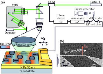
To probe the nanoscale spin waves we used a standard phase-resolved micro-BLS setup [21], see Fig. 1(a). The light from a single-mode laser (COBOLT Samba) with a wavelength of 532 nm passes through an electro-optical modulator (EOM, QUBIG TW-15M1-VIS), where the frequency of a tiny fraction of the light is blue- and red-shifted by the pumping frequency. The light is focused on the sample by objective lens with numerical aperture NA=0.75. The backscattered light is analyzed by the Tandem Fabry-Perot interferometer (TFPi, Tablestable, TFP2HC) with a single photon detector [22].
A single radio-frequency (RF) generator (Rohde & Schwarz SMB100B) is used to excite the spin waves by an excitation antenna and to drive the EOM at the same time. To ensure a temporal coherence of the EOM and the excited spin waves, the signal is split by a 3 dB power divider. Two RF switches are used to individually control the sample and EOM excitation. The power of both branches can be independently set by varying the output power of the signal generator and by a variable attenuator which is placed in the EOM branch. A motorized phase shifter, also placed in the EOM branch, allows to precisely set the phase difference between the excited spin waves and the reference signal from the EOM. The excitation antenna is contacted by RF picoprobes (GGB industries, Model 40A).
The sample consisted of a continuous Permalloy layer (30 nm-thick) deposited on a silicon substrate. The spin waves were excited by a stripline nanoantenna (180 nm wide, 105 nm thick multilayer stack: 10 nm SiO2/85 nm Cu/10 nm Au), fabricated by EBL and lift-off process. The antenna enabled excitation of spin waves with wavelengths down to [23, 24]. The square array consisting of 200 nm-wide and 60 nm-thick sputter-deposited silicon disks was fabricated by EBL and lift-off process in the vicinity of the antenna. The array had a lattice constant of 500 nm and a tilt of 8∘ with respect to the antenna. A scanning electron microscope image of the studied structure is shown in Fig. 1(b).
The Brillouin light scattering process is governed by laws of energy (frequency) and momentum (wavenumber) conservation [25, 26, 27]:
| (1) | |||
| (2) |
Here, denotes the frequency, denotes the wavenumber, denotes the reduced Planck constant and indices i s, and m stand for incident light, scattered light and magnons, respectively.
Without any complex momentum, in the case of backscattering geometry, these laws of conservation restrict the maximum wavenumber of the spin wave on which the light can be scattered only to the double wavenumber of the probing light [27]. We have recently shown [20], that this limitation can be overcome by concentrating the light into a subdiffraction region, i.e., by introducing the imaginary part of the photon’s momentum. This process can be described as an interaction between light and spin wave via magneto-optical coupling mechanism, where the susceptibility () is composed of a static and a dynamic parts [28, 29]. The time- and space-dependent susceptibility can be written as:
| (3) |
where is the static part, and are the dynamic components of the magnetization, and is the Voigt constant [28, 29]. The inelastic scattering (dynamic part of susceptibility) causes the formation of a polarization current at a frequency shifted by with respect to the driving field [30, 31, 29]
| (4) |
In our experiment, the momentum and the frequency are defined by the frequency of the RF generator and dispersion relation of spin waves. So in case of monochromatic coherent wave the induced polarization current reads as:
| (5) |
The above equation highlights the importance of field localization provided by the silicon disks: the spatial profile of determines the area that contributes to the collected BLS signal. If the modulation of the spatial profile of is larger than the spin-wave wavelength, the exponential factor is averaged out and the information about the spin wave is lost [20, 32]. On the other hand, intense hotspots generated by the silicon disk effectively limit the spatial extent of the induced polarization to a very small volume and thus facilitate the extraction of the spin-wave phase from BLS measurements.
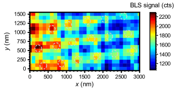
To confirm these findings, we performed a 2D scan of the BLS intensity in the vicinity of the excitation antenna which was connected to the RF generator with frequency set to 14.5 GHz, in an external magnetic field of 50 mT. The antenna thus excited coherent spin waves with wavevector ( nm) [33, 34]. Such short-wavelength spin waves are beyond the detection limit of conventional -BLS (the detection limit of our -BLS is [20], thus without any further enhancement we would see no signal. However, due to the subdiffraction localization of the -field by the silicon disks, we can observe a propagating spin wave with even such a short wavelength (see Fig. 2). The BLS signal naturally decays as the wave propagates further from the excitation antenna and it is strongly enhanced at the positions of the silicon disks. This agrees well with expectations based on Eq. (5).
In the second experiment, we focused on the measurement of the spatial evolution of the spin wave phase. During the BLS process the scattered photon acquires the phase of the spin wave and this phase can be reconstructed with the help of reference phase signal produced by the EOM. In this measurement both RF switches were switched on [see Fig. 1(a)], and we observed the interference of the light inelastically scattered on spin-waves with the light modulated by EOM [35]. In order to acquire the phase with spatial resolution sufficient to measure spin waves with very short wavelengths, we exploited the symmetry along -axis of the spin wave propagating perpendicularly from the excitation antenna and performed a linescan over one row of the silicon disk array [see Fig. 1(b)]. As the array is tilted by 8°, the distance of the disks from the antenna increases by 70 nm for each disk in the row.
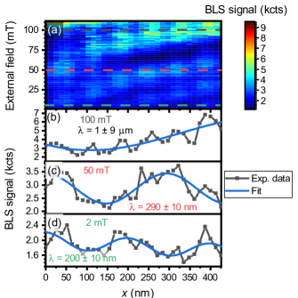
The measured dependence of the interference signal () on the distance from the excitation antenna and on the external magnetic field is plotted in Fig. 3(a). The cross sections of this plot at magnetic field values of 100 mT, 50 mT, and 2 mT are shown in Fig. 3 (b), (c) and (d), respectively. We can observe how the spin wave wavelengths shorten for the lower values of the external magnetic field. The shortening is apparent from the gradual change of the distance between the interference minima and maxima. To obtain the exact value of the spin wave wavelength, we fit the data with a two-wave interference model [36, 35]:
| (6) |
where and are parameters describing the signal intensity from the spin wave and the EOM, respectively, is the spin-wave wavelength, is the spin-wave decay length, and is the initial phase offset. The fitted wavelengths are in corresponding panels of Fig. 3.
Although it was possible to obtain spin-wave wavelengths from the BLS interference signal and nonlinear fitting with the two-wave interference model, the technique of the full-phase reconstruction [37, 38] proved to be much more robust and we used this technique to obtain the full spin-wave dispersion over a broad range of frequencies and -vectors. This technique requires four measurements to fully reconstruct the spin-wave phase. In order to account for thermally excited spin waves, we added fifth measurement, which must be taken into account if the coherent signal is comparable to the incoherent thermal background. To calculate the evolution of the spin-wave phase along the distance , real and imaginary parts of the wave amplitude have to be calculated:
| (7) | |||
| (8) |
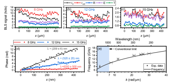
Here, is the interference signal with EOM phase shifted by 0 (), is the signal from coherent spin waves (which includes also a contribution from thermal spin waves), is the EOM signal, and is a signal from thermal spin waves. These signals are shown in Figs. 4(a), (b), and (c) for 8, 12, and 15 GHz, respectively. The spin-wave phase can be calculated as . In the case of a monochromatic spin wave, the dependence is linear and its slope directly represents the spin-wave wavenumber. The phases reconstructed from the experimental data in Fig. 4(a,b,c) are shown in Fig 4d, together with linear fits of their slopes.
The wavevectors extracted from the phase profiles acquired in the field of 50 mT at various frequencies are compared to the theoretical dispersion relation [see Fig. 4(e)] calculated according to the Kalinikos-Slavin model [33, 34]:
| (9) |
where is the spin-wave frequency, is its wavevector, , , is the saturation magnetization, GHz/T is the gyromagnetic ratio, is the permeability of a vacuum, nm is the exchange length, , and nm, is the thickness of the sample [20]. The excellent agreement between the theory and the experimental data [see Fig. 4(e)] for wavevectors ranging from 4 rad/m up to 30 rad/m means that we were able to reliably measure and reconstruct the spin wave phase even for spin-wave wavelengths where the BLS process had to be mediated by the silicon disk. The maximum measured wavevector corresponds to the excitation limit of the 180 nm-wide antenna [23, 24]. We anticipate that with another type of a spin wave source [39, 14, 40], spin waves with even shorter wavelengths could be measured.
When we look more carefully at the linescan data we can observe a periodic pattern [either areas with an increased signal nicely visible in Fig 3(b) or stair-like pattern in Fig 4(d)]. This pattern has a periodicity of 70 nm, which is the same as periodicity of the positions of the individual silicon disks under the scanning tilt. The linescans were acquired with oversampling, where the spatial step in the spin-waves propagation direction ( axis) was approx. 13 nm, while the distance between the silicon disks was approx. 70 nm. This periodic pattern in extracted phase [Fig. 4(e)] suggests that the detected phase is defined by the positions of the disks on the thin film and is not overly sensitive to the exact positioning of the laser spot relative to the position of the nanoresonator. Also note, that we were able to reliably measure the spin-wave wavelength = 4.2 m by scanning over a distance of 450 nm only. This would not be possible without precisely positioned detection points and without the full-phase reconstruction technique.
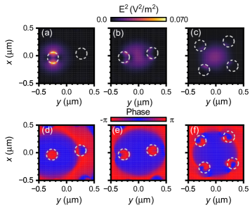
To clarify the phase stability when scanning over the array of silicon disks, we performed finite-differences-time-domain (FDTD) simulations. of the sample with the same parameters as in the experiments. The simulations were carried out in Lumerical software with the mesh cell set to 5 nm in all directions. More details can be found in [20]. Figure 5(a) shows the localization of electromagnetic field into hotspots, that allow the detection of high- spin waves. In this case the Gaussian beam is precisely positioned on the silicon disk. On the other hand, if we position the beam spot directly between the silicon disks [Fig. 5 (b-c)], this localization is absent, and the overall light intensity is lower. This results in a decrease of the detection sensitivity to high- spin waves and overall decrease of the BLS signal. We also extracted the phase of the electric field from the simulated data [Fig. 5(d-f)]. The phase in the axis of the linear polarization of the incident light () is homogeneous across the high intensity regions (hotspots), while the inner area of the disk has the opposite phase and this is the same for all simulated positions of the beam. This independence of the electric-field phase on exact position of the beam suggests the robustness of the phase reconstruction to, e.g., mechanical vibrations. Note that even though the two hotspots are localized on the disk edges and separated by 200 nm, this does not influence the capability of the system to detect even nanometer changes in the spin-wave wavelength. This is analogous to the case of inductive detection of spin waves by coplanar waveguides or meander antennas in propagating spin-wave spectroscopy experiments. There, the electromagnetic field distribution under relatively large detection antennas with complex geometries is also non-trivial, and still the spin wave phase can be measured [23, 41].
In conclusion, we demonstrated an efficient and simple technique for phase-resolved characterization of nanoscale spin waves based on conventional phase-resolved BLS microscopy. Presented technique uses weakly interacting arrays of Mie resonators which localize and enhance the electric field involved in the magneto-optical coupling and the connected BLS process. Short-wavelength spin waves can be detected, and their phase can be characterized with nanometer precision. This precision depends on the exact positioning of the nanoresonator in the array. With modern electron beam lithography techniques, sub-10 nm precision of placement of individual array elements is easily achievable. The presented experiments were limited only by the excitation efficiency of the used stripline nanoantenna. With the use of a different type of the spin-wave source it should be possible to detect spin waves with sub-100 nm wavelengths. Also, with the presented technique other types of BLS experiments, such as time-resolved measurements [42] can be easily performed on nanoscale spin waves. These results show that Mie-enhanced BLS microscopy is relevant and highly versatile tool for nanoscale magnonics research.
Acknowledgements.
We gratefully acknowledge CzechNanoLab project LM2018110 for the financial support of the measurements and sample fabrication at CEITEC Nano Research Infrastructure. O.W. was supported by Brno PhD talent scholarship and acknowledges BUT specific research project. F.L. acknowledges the support by the Grant Agency of the Czech Republic (21-29468S). J.H. acknowledges a support from the project Quality Internal Grants of BUT (KInG BUT), Reg. No. CZ.02.2.69 / 0.0 / 0.0 / 19_073 / 0016948, which is financed from the OP RDE.References
- IRD [2022] The international roadmap for devices and systems 2022 update: Beyond CMOS (2022).
- Wang et al. [2020] Q. Wang, M. Kewenig, M. Schneider, R. Verba, F. Kohl, B. Heinz, M. Geilen, M. Mohseni, B. Lägel, F. Ciubotaru, et al., A magnonic directional coupler for integrated magnonic half-adders, Nat. Electron. 3, 765 (2020).
- Wang et al. [2021] Q. Wang, A. V. Chumak, and P. Pirro, Inverse-design magnonic devices, Nat. Commun. 12, 2636 (2021).
- Papp et al. [2021] Á. Papp, W. Porod, and G. Csaba, Nanoscale neural network using non-linear spin-wave interference, Nat. Commun. 12, 6422 (2021).
- Chumak et al. [2022] A. V. Chumak, P. Kabos, M. Wu, C. Abert, C. Adelmann, A. Adeyeye, J. Åkerman, F. G. Aliev, A. Anane, A. Awad, et al., Roadmap on spin-wave computing, IEEE Trans. Magn. , 1 (2022).
- Wang et al. [2019] Q. Wang, B. Heinz, R. Verba, M. Kewenig, P. Pirro, M. Schneider, T. Meyer, B. Lägel, C. Dubs, T. Brächer, et al., Spin pinning and spin-wave dispersion in nanoscopic ferromagnetic waveguides, Phys. Rev. Lett. 122, 247202 (2019).
- Dreyer et al. [2022] R. Dreyer, A. F. Schäffer, H. G. Bauer, N. Liebing, J. Berakdar, and G. Woltersdorf, Imaging and phase-locking of non-linear spin waves, Nat. Commun. 13, 4939 (2022).
- Heinz et al. [2022] B. Heinz, M. Mohseni, A. Lentfert, R. Verba, M. Schneider, B. Lägel, K. Levchenko, T. Brächer, C. Dubs, A. V. Chumak, et al., Parametric generation of spin waves in nanoscaled magnonic conduits, Phys. Rev. B 105, 144424 (2022).
- Koerner et al. [2022] C. Koerner, R. Dreyer, M. Wagener, N. Liebing, H. G. Bauer, and G. Woltersdorf, Frequency multiplication by collective nanoscale spin-wave dynamics, Science 375, 1165 (2022).
- Che et al. [2021] P. Che, I. Stasinopoulos, A. Mucchietto, J. Li, H. Berger, A. Bauer, C. Pfleiderer, and D. Grundler, Confined dipole and exchange spin waves in a bulk chiral magnet with Dzyaloshinskii-Moriya interaction, Phys. Rev. Res. 3, 033104 (2021).
- Jersch et al. [2010] J. Jersch, V. Demidov, H. Fuchs, K. Rott, P. Krzysteczko, J. Münchenberger, G. Reiss, and S. Demokritov, Mapping of localized spin-wave excitations by near-field Brillouin light scattering, Appl. Phys. Lett. 97, 152502 (2010).
- Wojewoda et al. [2020] O. Wojewoda, T. Hula, L. Flajšman, M. Vaňatka, J. Gloss, J. Holobrádek, M. Staňo, S. Stienen, L. Körber, K. Schultheiß, et al., Propagation of spin waves through a Néel domain wall, Appl. Phys. Lett. 117, 022405 (2020).
- Yu et al. [2013] H. Yu, G. Duerr, R. Huber, M. Bahr, T. Schwarze, F. Brandl, and D. Grundler, Omnidirectional spin-wave nanograting coupler, Nat. Commun. 4, 2702 (2013).
- Mayr et al. [2021] S. Mayr, L. Flajšman, S. Finizio, A. Hrabec, M. Weigand, J. Förster, H. Stoll, L. J. Heyderman, M. Urbánek, S. Wintz, et al., Spin-wave emission from vortex cores under static magnetic bias fields, Nano Lett. 21, 1584 (2021).
- Dieterle et al. [2019] G. Dieterle, J. Förster, H. Stoll, A. Semisalova, S. Finizio, A. Gangwar, M. Weigand, M. Noske, M. Fähnle, I. Bykova, et al., Coherent excitation of heterosymmetric spin waves with ultrashort wavelengths, Phys. Rev. Lett. 122, 117202 (2019).
- Albisetti et al. [2018] E. Albisetti, D. Petti, G. Sala, R. Silvani, S. Tacchi, S. Finizio, S. Wintz, A. Calò, X. Zheng, J. Raabe, et al., Nanoscale spin-wave circuits based on engineered reconfigurable spin-textures, Commun. Phys. 1, 56 (2018).
- Sluka et al. [2019] V. Sluka, T. Schneider, R. A. Gallardo, A. Kákay, M. Weigand, T. Warnatz, R. Mattheis, A. Roldán-Molina, P. Landeros, V. Tiberkevich, et al., Emission and propagation of 1d and 2d spin waves with nanoscale wavelengths in anisotropic spin textures, Nat. Nanotechnol. 14, 328 (2019).
- Wintz et al. [2016] S. Wintz, V. Tiberkevich, M. Weigand, J. Raabe, J. Lindner, A. Erbe, A. Slavin, and J. Fassbender, Magnetic vortex cores as tunable spin-wave emitters, Nat. Nanotechnol. 11, 948 (2016).
- Kimel et al. [2022] A. Kimel, A. Zvezdin, S. Sharma, S. Shallcross, N. De Sousa, A. Garcia-Martin, G. Salvan, J. Hamrle, O. Stejskal, J. McCord, et al., The 2022 magneto-optics roadmap, J. Phys. D Appl. Phys. 55, 463003 (2022).
- Wojewoda et al. [2022] O. Wojewoda, F. Ligmajer, M. Hrtoň, J. Klíma, M. Dhankhar, K. Davídková, M. Staňo, J. Holobrádek, J. Zlámal, T. Šikola, and M. Urbánek, Observing high-k magnons with Mie-resonance-enhanced Brillouin light scattering, arXiv preprint arXiv:2206.05178 10.48550/arXiv.2206.05178 (2022).
- Flajšman et al. [2022] L. Flajšman, O. Wojewoda, H. Qin, K. Davídková, M. Urbánek, and S. van Dijken, Wideband Brillouin light scattering analysis of spin waves excited by a white-noise RF generator, Appl. Phys. Lett. 121, 232402 (2022).
- Lindsay et al. [1981] S. M. Lindsay, M. W. Anderson, and J. R. Sandercock, Construction and alignment of a high performance multipass vernier tandem Fabry–Perot interferometer, Rev. Sci. Instrum. 52, 1478 (1981).
- Vaňatka et al. [2021] M. Vaňatka, K. Szulc, O. Wojewoda, C. Dubs, A. V. Chumak, M. Krawczyk, O. V. Dobrovolskiy, J. W. Kłos, and M. Urbánek, Spin-wave dispersion measurement by variable-gap propagating spin-wave spectroscopy, Phys. Rev. Appl. 16, 054033 (2021).
- Vlaminck and Bailleul [2010] V. Vlaminck and M. Bailleul, Spin-wave transduction at the submicrometer scale: Experiment and modeling, Phys. Rev. B 81, 014425 (2010).
- Kargar and Balandin [2021] F. Kargar and A. A. Balandin, Advances in Brillouin–Mandelstam light-scattering spectroscopy, Nat. Photonics 15, 720 (2021).
- Madami et al. [2012] M. Madami, G. Gubbiotti, S. Tacchi, and G. Carlotti, Chapter two - application of microfocused Brillouin light scattering to the study of spin waves in low-dimensional magnetic systems (Academic Press, 2012) pp. 79–150.
- Sebastian et al. [2015] T. Sebastian, K. Schultheiss, B. Obry, B. Hillebrands, and H. Schultheiss, Micro-focused Brillouin light scattering: imaging spin waves at the nanoscale, Front. Phys. 3, 35 (2015).
- Qiu and Bader [2000] Z. Q. Qiu and S. D. Bader, Surface magneto-optic Kerr effect, Rev. Sci. Instrum. 71, 1243 (2000).
- Cottam and Lockwood [1986] M. G. Cottam and D. J. Lockwood, Light scattering in magnetic solids (Wiley New York, 1986).
- Landau et al. [2013] L. D. Landau, J. Bell, M. Kearsley, L. Pitaevskii, E. Lifshitz, and J. Sykes, Electrodynamics of continuous media, Vol. 8 (Elsevier, 2013).
- Cottam [1976] M. G. Cottam, Theory of light scattering off the surface of a Heisenberg ferromagnet, J. Phys. Condens. Matte. 9, 2137 (1976).
- Freeman et al. [2020] R. Freeman, R. Lemasters, T. Kalejaiye, F. Wang, G. Chen, J. Ding, M. Wu, V. E. Demidov, S. O. Demokritov, H. Harutyunyan, and S. Urazhdin, Brillouin light scattering of spin waves inaccessible with free-space light, Phys. Rev. Res. 2, 033427 (2020).
- Kalinikos and Slavin [1986] B. Kalinikos and A. Slavin, Theory of dipole-exchange spin wave spectrum for ferromagnetic films with mixed exchange boundary conditions, J. Phys. Condens. Matte. 19, 7013 (1986).
- Wojewoda [2023] O. Wojewoda, Spin-wave toolkit, GitHub (2023).
- Vogt et al. [2009] K. Vogt, H. Schultheiss, S. Hermsdoerfer, P. Pirro, A. Serga, and B. Hillebrands, All-optical detection of phase fronts of propagating spin waves in a Ni81Fe19 microstripe, Appl. Phys. Lett. 95, 182508 (2009).
- Flajšman et al. [2020] L. Flajšman, K. Wagner, M. Vaňatka, J. Gloss, V. Křižáková, M. Schmid, H. Schultheiss, and M. Urbánek, Zero-field propagation of spin waves in waveguides prepared by focused ion beam direct writing, Phys. Rev. B 101, 014436 (2020).
- Serga et al. [2006] A. Serga, T. Schneider, B. Hillebrands, S. Demokritov, and M. Kostylev, Phase-sensitive Brillouin light scattering spectroscopy from spin-wave packets, Appl. Phys. Lett. 89, 063506 (2006).
- Bouchal et al. [2019] P. Bouchal, P. Dvorak, J. Babocky, Z. Bouchal, F. Ligmajer, M. Hrton, V. Krapek, A. Fassbender, S. Linden, R. Chmelik, et al., High-resolution quantitative phase imaging of plasmonic metasurfaces with sensitivity down to a single nanoantenna, Nano Lett. 19, 1242 (2019).
- Baumgaertl et al. [2020] K. Baumgaertl, J. Gräfe, P. Che, A. Mucchietto, J. Förster, N. Träger, M. Bechtel, M. Weigand, G. Schütz, and D. Grundler, Nanoimaging of ultrashort magnon emission by ferromagnetic grating couplers at GHz frequencies, Nano Lett. 20, 7281 (2020).
- Urazhdin et al. [2014] S. Urazhdin, V. Demidov, H. Ulrichs, T. Kendziorczyk, T. Kuhn, J. Leuthold, G. Wilde, and S. Demokritov, Nanomagnonic devices based on the spin-transfer torque, Nat. Nanotechnol. 9, 509 (2014).
- Lucassen et al. [2019] J. Lucassen, C. F. Schippers, L. Rutten, R. A. Duine, H. J. Swagten, B. Koopmans, and R. Lavrijsen, Optimizing propagating spin wave spectroscopy, Appl. Phys. Lett. 115, 012403 (2019).
- Merbouche et al. [2022] H. Merbouche, B. Divinskiy, K. Nikolaev, C. Kaspar, W. Pernice, D. Gouéré, R. Lebrun, V. Cros, J. Ben Youssef, P. Bortolotti, et al., Giant nonlinear self-phase modulation of large-amplitude spin waves in microscopic YIG waveguides, Sci. Rep. 12, 7246 (2022).