3D Printed Graded Porous Sensors for Soft Sensorized Insoles with Gait Phase & Ground Reaction Forces Estimation
Abstract
Sensorized insoles provide a tool to perform gait studies and health monitoring during daily life. These sensorized insoles need to be comfortable and lightweight to be accepted. Previous work has already demonstrated that sensorized insoles are possible and can estimate both ground reaction force and gait cycle. However, these are often assemblies of commercial components restricting design freedom and flexibility. Within this work, we investigate the feasibility of using four 3D-printed porous (foam-like) piezoresistive sensors embedded in a commercial insole. These sensors were evaluated using an instrumented treadmill as the golden standard. It was observed that the four sensors behaved in line with the expected change in pressure distribution during the gait cycle. In addition, Hammerstein-Wiener models were identified that were capable of estimating the vertical and mediolateral ground reaction forces (GRFs). Their NRMSE fits were on average 82% and 73%, respectively. Similarly, for the averaged gait cycle the values were 0.98 and 0.99 with normalized RMS errors overall below 6%. These values were comparable with other insoles based on commercial force sensing resistors but at a significantly lower cost (over four times cheaper). Thereby indicating that our 3D-printed sensors can be an interesting option for sensorized insoles. The advantage of 3D printing these sensors is that it allows for significantly more design freedom, reduces assembly, and is cheaper. However, further research is needed to exploit this design freedom for complex sensors, estimate the anteroposterior GRF, and fully 3D print the entire insole.
1 Introduction
With the current boom in the use of advanced health monitoring technologies for both medical and personal use, wearables have become a large part of day-to-day lives 1. The use of smartwatches and heart rate monitors for sports, and recreational activities, as well as monitoring of health conditions, is steadily on the rise to maintain optimal physical performance2. Biological markers such as cardiac rhythm, blood pressure, and respiratory variables have been investigated using smartphones and -watches 3, 4 to predict the onset of ailments such as sleep apnea and stroke. Although useful, these technologies are limited to the estimation of a hand full of bio variables only restricted by the type of sensors available for use5.
In the field of kinesiology, the estimation of moments about the joints in the human body has been vastly studied for understanding human biomechanics as well as applying them to sports science and wearable robotics. For the estimation of biological joint torques, the use of motion capture systems in conjunction with force plates has been widely utilized 6. This setup is highly accurate but cannot be utilized in outdoor scenarios. Therefore, wearable sensors offer several benefits over commercially available smart devices such as phones and watches. Typically, inertial measurement units have been utilized to estimate the kinematics of the human body during outdoor tasks 7. However, several assumptions such as person-specific limb mass and the location center of mass have to be made and can be tedious to obtain due to the required complex equipment such as 3D scanners8.
Therefore, several groups have worked on designing insole sensors for measuring ground reaction forces via the use of several types of sensors. Commercially available load cells have been utilized for sensing insoles 9 but have the downside of being bulky. Hence, soft sensors could be a good candidate for force sensing as demonstrated by Kong et. al10 via air pressure sensors embedded in the shoe. Furthermore, several insoles sensors that use capacitive sensors embedded in textiles11 as well as piezo-resistive sensors12 have been researched and are only limited to measurement of normal force and the center of pressure, not shear. Typically, the aforementioned sensors also require careful and manual manufacturing processes such as moulding13 and manually coiling a tube 14. Therefore techniques such as 3D printing can reduce the complexity of manually manufacturing these devices as well as human error.
With the advances in additive manufacturing, it is now possible to 3D print compliant materials such as thermoplastic elastomers15. Furthermore, the printing of these materials is not limited to the material properties but several groups have demonstrated the printing of conductive polymers16 and their applications in sensors. Moreover, 3D printing has been utilized to customize shoe insoles for diabetic feet using porous structures 17. These insoles could be further printed using a sensorized material and used to measure contact forces at the foot during various activities. This work aims to bridge the gap literature by presenting a sensorized insole using 3D printed graded porous sensors to estimate GRFs as well as gait phases during walking as shown in Fig. 1. Compared to other soft insole sensors in literature, the presented insoles leverages additive manufacturing to fabricate the sensing elements. Furthermore, the presented sensors can be manufactured at a cost four times lower than insoles assembled with off-the-shelf force sensing resistors.
This paper is organized as follows. Section II details the design of the soft sensorized insole, its fabrication method, and the test procedure used to evaluate the insole. Section III, presents the results from the estimation of gait cycles during walking, vertical ground reaction forces, and estimation of mediolateral GRFs using system identification. The conclusions from this work and future work are detailed in Section IV.
2 Materials and Methods
2.1 Soft Sensorized Insole Design & Force Estimation Method
The insole consists of four individual layers: a soft foam layer that embeds the sensor, two insulating (top and bottom) layers, and a layer with grounding electrodes (Fig. 2(a)). The purpose of the insulating layers was to prevent the user from creating an additional conductive path. In addition, they were used to package the entire structure.
The sensing was implemented using the other two layers by adding piezoresistive porous (foam-like) sensors. These piezoresistive sensors 18, 19, 20 change their resistance when subjected to a load. The resistance of the sensors was measured using a voltage divider (see Fig. 2(b)). To realize the voltage dividers a common grounding layer was added inside the insole. A small strip was left at the edge of the common ground layer to provide a place outside the user’s shoe for connecting the grounding electrode.
To estimate the gait cycle and ground reaction force, four sensors were added. These sensors were distributed over the entire length of the foot. Specifically, the sensors were added at the heel(HL), midfoot(MF), metatarsal(MT), and toes(TO) (Fig. 2(a)). These locations allow for the reconstruction of aspects of the gait cycle such as heel strike and toe-off.
The four piezoresistive porous sensors change resistance when subjected to a force. Within this work, the change in resistance is used for force estimation. The change in resistance is defined as (with the resistance when the user is standing still at the start)
| (1) |
This change in resistance can be exploited to estimate the gait cycle behavior. Unfortunately, the change in resistance of piezoresistive porous sensors is nonlinear and exhibits hysteresis. This behavior needs to be compensated for to estimate the ground reaction forces more accurately. In literature, people solve this by using a model-based compensation, such as a Hammerstein-Wiener (HW) model21, 18, training a neural network22 and/or other machine learning tools 23. Within this work, the HW model is employed as it is simple yet able to provide good force estimates, as seen in 21. This model class is shown in Figure 2(b) and consists of three components: two nonlinear functions () and a linear transfer function () in the middle, which gives
| (2) |
Within this equation, the variable represents the ground reaction forces that need to be estimated. Note that the nonlinear input function consists of four nonlinear functions (one for each sensor). The HW models can be identified using MATLAB’s (The MathWorks, USA) System Identification Toolbox. Within this work, piecewise linear activation functions were used as these gave good results for strain18 and force estimation21. The number of breakpoints was determined experimentally by trying different combinations in the range of five to ten per activation function. Combining the four sensors and an HW model allows for both gait cycle estimation and ground reaction force estimation.
2.2 Insole Prototype
Fabrication of the insole was done in five steps. The first step was to print the porous sensors. The sensors were printed using our InFoam method 24. This method exploits the liquid rope coiling effect to print structures with a graded porosity. Specifically, it uses the empty space of the coils to create pores leading to a structure with programmable porosity. Within this work, a modified Ender 5 Plus (Shenzhen Creality 3D Technology Co., Ltd., China) with a custom screw extruder was used. The screw extruder used TC7OEX-BLCK pellets (Kraiburg TPE, Germany) that have a Shore Hardness of 70A and volume resistivity of 10 cm. These were printed at 195∘C with a 0.6 mm nozzle. Using this material three blocks of 60x60x8 mm3 were printed that were cut to 60 mm by [20,25,20,30] mm blocks for the toe, metatarsal, midfoot, and heel sensor, respectively. The blocks were printed with three levels of porosity [84,71,64]%. Other works indicate that the introduction of a stiffness gradient can enable a larger range of measurement 25.
In the second step, a sheet of polyethylene foam (thickness of 5 mm) was cut to shoe size 43 (EU). Four pockets of appropriate size (see above) were cut at the toe, metatarsal, midfoot, and heel for embedding the sensors. Subsequently, the 3D printed sensors were placed in each pocket, as seen in Fig. 2(c). An electrode (a copper wire) was attached to every sensor. These electrodes were soldered to the sensor by using the conductive TPE itself (Fig. 2(c)). Lastly, the wires were guided through the insole’s edge by using tape to have a single point of entry on the side of the foot.
Afterwards, the common grounding layer was added. using a woven sheet of conductive textile (Adafruit, USA). Lastly, to finalize the insole, an insulating layer was added on top and the bottom of the insole by adding insulating tape.
2.3 Sensorized Insole Testing
The sensorized insole was embedded in a shoe (Fig. 3(a)) for testing. The wiring of the insole was attached to the subject by using elastic bands with velcro (Fig. 3(a)) to ensure the wires do not influence the walking motion. The subject, who does not have an abnormal gait pattern, walked on an instrumented treadmill (Qualisys AB, Sweden) with split belt force plates (AMTI, USA). The instrumented treadmill was used to record the ground reaction forces of both feet. Walking trials were performed on the treadmill with speeds of 1, 1.5, and 2 m/s for approximately 40 seconds each. This walking trial was performed three times. During these trials, the changes in resistance were recorded using the measurement setup of Fig. 3(b). The first walking trial was used for identification. Whereas the other two trials are used as validation datasets for the identified models. The subject was one of the authors who consented to participate in the study. Within this study, we only performed technical tests during simple walking and no personal data was collected. Therefore, no review was performed.
The measurement setup used a voltage divider to measure the resistance of the sensor using a bias resistor of 560. The output voltage was measured using a 16-bit analog-to-digital converter ADS1115 (Texas Instruments, USA) on a breakout board (Adafruit, USA) that is connected to an Arduino Uno (Arduino AG, Italy). The Arduino streamed data over USB to a laptop for further processing. The measured voltages were then converted to resistance by
| (3) |
Within this equation, the variables and represent the input (5 V from Arduino) and measured voltage, respectively. The resistance changes were then computed by using and Eq. 1. The changes in resistance were then used to identify a linear and Hammerstein-Wiener model. The model with the highest normalized root mean square fit (NRSME) kept, which was defined as (using the two norm):
| (4) |
Within this equation, the variables , , and represent the measured force, predicted force, and average (measured) force. In addition, the models were also compared in terms of their RMS error scaled by the maximum force. Lastly, the coefficient of determination was computed by comparing the measured and estimated GRF.
3 Results and Discussion
3.1 Gait Cycle Estimation
The vertical ground reaction force (GRF) versus gait cycle is shown in Fig. 4(a,b) in error bar format. A typical gait cycle can be observed with a clear heel strike (%), mid stance ( to 50%), and toe-off (%)6. The resistance change curve (Fig. 4(b)) has an overall similar shape as the gait cycle but is inverted. The inverted shape is to be expected as an increased force means a decrease in resistance. Interestingly, there seems to be some overlap with regions of higher variance in the force transients (i.e. between heel strike and mid stance and after toe-off) in both the GRF and resistance change, which implies a correlation between the force magnitude and resistance change that can be beneficial in force estimation.
Besides similarities in the general shape, the sensors show the change in pressure distribution over the gait cycle, which corresponds with the gait phase (Fig. 4(c)). During heel strike and towards midstance the heel, midfoot, metatarsal, and toe sensors activate successively. Indicating a gradual (expected) change in force distribution from the heel to encompassing the entire foot during mid-stance. Within the mid-stance, all sensors measure something. This behavior indicates that the entire foot is on the ground. However, one can see an increase in force on the midfoot, metatarsal, and toe sensor indicating that the subject is shifting weight towards his toes (as expected). Afterward from mid stance towards toe off, all sensors show relaxation in the same order as the heel strike event (i.e. from heel to toe). This successive relaxation indicates that an increasing number of sensors do not experience a load anymore. Moreover, the shift in force towards the metatarsal/toe should be right before the toe off, as also seen in our sensor. These results imply that the sensors correctly capture the force distribution.
3.2 Vertical Ground Reaction Forces
The vertical (V) and mediolateral (ML) GRFs were estimated using identified HW and linear models based on the changes in resistance. The HW and linear models were identified separately for the V and ML GRFs for both feet. The averaged GRFs of the identified models for the V GRF are shown in Fig. 5(a-d) for both feet. These figures show the identified models’ performance for the identification (5(a,c)) and validation dataset (5(b,d)). In general, it can be observed that the linear model is better at capturing the two peaks whereas the low forces are better captured by the HW model. However, both seem to follow the trajectory of the force plate.
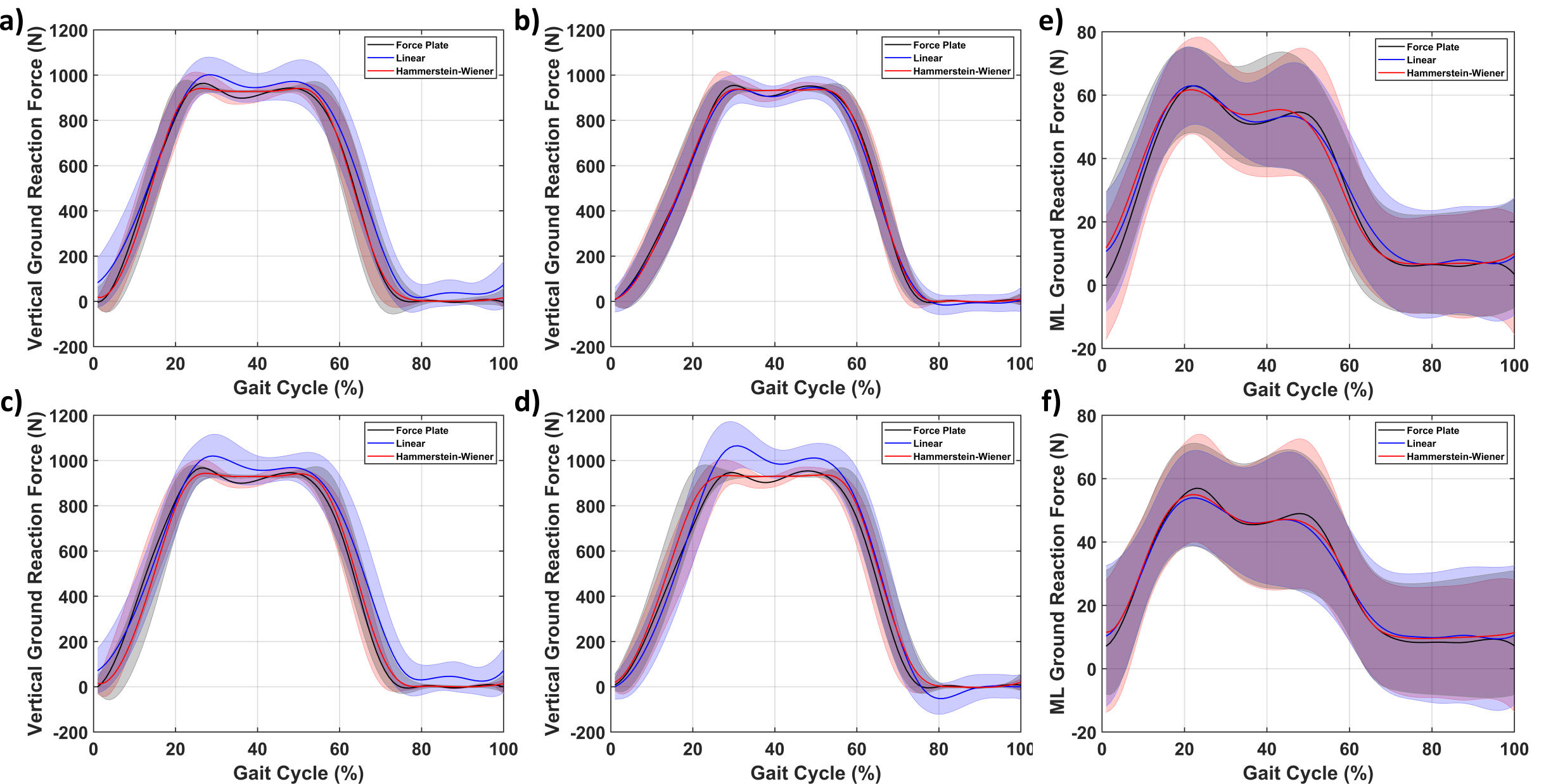
The overlap is confirmed by the NRMSE (normalized root mean square) fit of the time-series data (computed using MATLAB’s compare-function) of 87/81% for the identification set for the HW/linear model of the left foot, respectively. Similar to our previous work 18 the HW model outperforms the linear model significantly with an error reduction of 31.5%. The capability of the HW model to better estimate force is also seen for the validation datasets with NRMSE fits of [81,75]% and [74,67] % for the HW and linear model for the left foot, respectively. Thereby providing evidence that the HW model also generalized well with the other datasets (as its fit was reduced slightly less). Similar results were obtained for the right foot with identification and validation NRMSE fits for the HW and linear model averaging 84.1% and 78.0%, respectively. Indicating that this model type is suitable for the estimation of vertical GRFs. For visualization of the estimation performance, the estimated and real GRFs during gait are visualized in the supplementary movie. The estimated and real GRF were evaluated for its -value (based on the averaged gait cycle), which gave an average of 0.976 and 0.982 for the linear and HW model, respectively. Thereby indicating that both models correlate quite well with the GRF. Similarly, the RMS error normalized by the maximum force also indicated good performance with an average of 6.24 and 3.72% for the linear and HW model, respectively. Indicating again that the HW model is better overall. Although it is interesting to note that the shape of the linear model is better but overall it seems less capable of estimating the GRF. A more in-depth comparison of this estimation performance with other insoles is provided in Section III-D.
3.3 Mediolateral Ground Reaction Forces
The mediolateral (ML) GRFs were also predicted using the changes in resistance and identified models. Their result is shown in Fig. 5(e) and (f) for the identification and validation dataset of the left foot, respectively. Similar to the vertical GRFs the estimated models behave similarly to the ground truth showing similar peak-valley-peak behavior. Although the HW model has better captured this trajectory than the vertical GRF. The first peak seems to be captured better than the second peak in terms of magnitude but the overall behavior is consistent with the force plate data.
The same observation as for the vertical GRFs can be made namely: the linear model is less accurate than the HW model. This observation is made for both the identification (NRMSE fit of the time-series data of 80% vs. 74%) and the validation datasets ([72,69]% and [67,63]%) of the left foot. Similarly, the linear and HW model for the ML GRF were also identified for the right foot. The NRMSE fits of these models gave an average of 73.7 and 68.1 % for the HW and linear models, respectively. Thereby indicating comparable results to the left foot. Similarly, the -values were 0.990(HW) and 0.983(linear) implying that the HW correlates slightly better. Lastly, even with the (relatively) lower NRMSE fits the range (maximum minus minimum) normalized RMS error was 3.9% (HW) and 5.1% (linear), respectively. Thereby implying a reasonable estimation of the mediolateral GRF. Similar to the vertical GRFs, the predicted and real ML GRFs are visualized in the supplementary movie as well. It is important to note that these fits are lower than the vertical GRFs in general.
3.4 Insole Comparison
The developed insoles are capable of estimating the gait cycle and the ground reaction forces (GRF). To put the acquired fits into context the insole will be compared to several force-sensing insoles. The focus will be on force sensing resistors (FSRs) as these are the most comparable technology. Firstly, the cost of fabricating (customizable) sensorized insoles in-house is much lower than assembling them using off-the-shelf FSRs. As both are piezoresistive sensors the required electronics are assumed to be equivalent. For printing both insoles completely around 85 grams of material would be necessary. Assuming a cost of 5-100 euro/kg for elastomeric pellets, the total price would range from 0.43 to 8.50 euros for both insoles. In contrast, if one would assemble the insole using commercial off-the-shelf FSRs with the cheapest around 3.87 euros on Farnell (The Netherlands) then two insoles with four sensors would cost 30.96 euros. Thus, printing the insoles is 73.7-3.64 times cheaper while also providing more design freedom compared to assembling off-the-shelf FSRs. Lastly, the inherent soft foam-like nature of our sensors could make the insole more comfortable for the user. In terms of performance, the presented insoles are capable of estimating the phases of gait during walking making them on par with other insoles such as26, 11. Similar to those works our insoles can provide gait cycle data. However, our insoles can also estimate ground reaction forces during gait. A table comparing our results with three other insoles is shown in Table 1 (averaging the left and right foot results). The absolute RMS error is the RMS error without scaling with the maximum force. The most notable aspect is that all works use different models for compensation and/or multiple subjects. This difference makes absolute comparisons of the metrics difficult. It can be observed that our insoles perform comparably in terms of the coefficient of determination for the vertical forces (). The insole of 14 comes near our but was only based on their repeatability testing, not GRFs. The RMSE values (based on the averaged dataset) vary significantly but are in the same order of magnitude. Normalizing by the maximum force shows similar values.
| Metric | Our Insole | FSR-122 | FSR-2 23 | Pneumatic 14 |
|---|---|---|---|---|
| No. sensors | 4 | 6 | 6 | 4 |
| Principle | Piezoresistive | Piezoresistive | Piezoresistive | Pressure |
| Model | HW | ANN | Random Forest | Hysteresis Compensator |
| (, ) (%) | 0.98, 0.99 | 0.96 | 0.91,0.59 | 0.98* |
| Absolute RMSE (, ) (N) | 37.3, 2.26 | 32.7, n/a | 65.7, 10.7 | 194, n/a |
| Rounded RMSE (, ) (%) | 4, 4 | 5, n/a | 8, 13 | 32, n/a |
The mediolateral () forces were also estimated in 23. Their is much lower than ours just like their RMS error. Indicating that our sensor is quite capable of estimating forces. Overall our insole sensors are at least comparable to other insoles. However, our insole uses two sensors less than the other two FSR-based insoles. With its comparable performance, it does indicate that for gait analysis our porous sensors can work similarly to FSR-based insoles. However, the other two works also investigated the center of pressure (both) and the ante posterior GRF 23. These were not investigated and, therefore, not compared.
4 Conclusion
Sensorized insoles can provide insight into aspects such as gait studies and health monitoring. For such insoles to be used in daily life they need to be discrete, lightweight, and non-intrusive. Within this work, we showcased a soft sensorized insole with 3D-printed porous (foam-like) sensors embedded.
The resistance changes versus the gait cycle indicate that the gait pattern can be deduced from the sensor data. Moreover, the identified models for the vertical GRF with NRMSE fits of 87-75% for the HW models and slightly lower for the linear (81-67%). A similar result is seen for the mediolateral GRF albeit a bit lower (80-66% and 74-63%, respectively). The estimation capabilities of our insoles are comparable to three other insoles (two FSRs and a pneumatic). Thereby indicating that our 3D printed sensors can reach similar performance at a much lower price point (more than 4x as cheap).
Future research on these insoles should include investigating their resilience over longer timespans. In addition, the full 3D printing of the sensorized insole can reduce cost and increase design flexibility. The full 3D printing of the insole also allows for the integration of more complex sensors and/or electrode placement, which can improve GRF estimation (mediolateral and vertical). Furthermore, these sensors could enable the estimation of the centers of pressure and ante-posterior GRFs. This addition would allow for a full reconstruction of the GRFs during gait. Also, other movements could be investigated to evaluate their performance in other scenarios.
References
- 1 M. N. K. Boulos, S. Wheeler, C. Tavares, and R. Jones, “How smartphones are changing the face of mobile and participatory healthcare: an overview, with example from ecaalyx,” Biomedical engineering online, vol. 10, no. 1, pp. 1–14, 2011.
- 2 M. Pobiruchin et al., “Accuracy and adoption of wearable technology used by active citizens: a marathon event field study,” JMIR mHealth and uHealth, vol. 5, no. 2, p. e6395, 2017.
- 3 F. Michard, “Toward smart monitoring with phones, watches, and wearable sensors,” Anesthesiology Clinics, vol. 39, no. 3, pp. 555–564, 2021.
- 4 T. Liang and Y. J. Yuan, “Wearable medical monitoring systems based on wireless networks: A review,” IEEE Sensors Journal, vol. 16, no. 23, pp. 8186–8199, 2016.
- 5 T.-C. Lu, C.-M. Fu, M. H.-M. Ma, C.-C. Fang, and A. M. Turner, “Healthcare applications of smart watches,” Applied clinical informatics, vol. 7, no. 03, pp. 850–869, 2016.
- 6 M. W. Whittle, Gait analysis: an introduction. Butterworth-Heinemann, 2014.
- 7 A. Karatsidis, G. Bellusci, H. M. Schepers, M. De Zee, M. S. Andersen, and P. H. Veltink, “Estimation of ground reaction forces and moments during gait using only inertial motion capture,” Sensors, vol. 17, no. 1, p. 75, 2016.
- 8 P. L. Davidson, S. J. Wilson, B. D. Wilson, and D. J. Chalmers, “Estimating subject-specific body segment parameters using a 3-dimensional modeller program,” Journal of biomechanics, vol. 41, no. 16, pp. 3506–3510, 2008.
- 9 P. H. Veltink, C. Liedtke, E. Droog, and H. van der Kooij, “Ambulatory measurement of ground reaction forces,” IEEE Transactions on Neural Systems and Rehabilitation Engineering, vol. 13, no. 3, pp. 423–427, 2005.
- 10 K. Kong and M. Tomizuka, “A gait monitoring system based on air pressure sensors embedded in a shoe,” IEEE/ASME Transactions on mechatronics, vol. 14, no. 3, pp. 358–370, 2009.
- 11 Q. Zhang, Y. L. Wang, Y. Xia, X. Wu, T. V. Kirk, and X. D. Chen, “A low-cost and highly integrated sensing insole for plantar pressure measurement,” Sensing and Bio-Sensing Res., vol. 26, p. 100298, 2019.
- 12 R. de Fazio, E. Perrone, R. Velázquez, M. De Vittorio, and P. Visconti, “Development of a self-powered piezo-resistive smart insole equipped with low-power ble connectivity for remote gait monitoring,” Sensors, vol. 21, no. 13, p. 4539, 2021.
- 13 K. Kim, S. Shin, and K. Kong, “An air-filled pad with elastomeric pillar array designed for a force-sensing insole,” IEEE Sensors Journal, vol. 18, no. 10, pp. 3968–3976, 2018.
- 14 S. Wachtel, B. Hassett, Z. Qiao, P. T. Chinimilli, and W. Zhang, “Design and characterization of shoe embedded pressure sensors for gait analysis and rehabilitation,” in Frontiers in Biomedical Devices, vol. 40672. American Society of Mechanical Engineers, 2017, p. V001T05A005.
- 15 M. Saari, M. Galla, B. Cox, P. Krueger, A. Cohen, and E. Richer, “Additive manufacturing of soft and composite parts from thermoplastic elastomers,” in 2015 International Solid Freeform Fabrication Symposium. University of Texas at Austin, 2015.
- 16 M. Criado-Gonzalez, A. Dominguez-Alfaro, N. Lopez-Larrea, N. Alegret, and D. Mecerreyes, “Additive manufacturing of conducting polymers: Recent advances, challenges, and opportunities,” ACS Applied Polymer Materials, vol. 3, no. 6, pp. 2865–2883, 2021.
- 17 Z. Ma et al., “Design and 3d printing of adjustable modulus porous structures for customized diabetic foot insoles,” International Journal of Lightweight Materials and Manufacture, vol. 2, no. 1, pp. 57–63, 2019.
- 18 N. Willemstein, H. van der Kooij, and A. Sadeghi, “3d printed proprioceptive soft fluidic actuators with graded porosity,” arXiv preprint arXiv:2302.13141, 2023.
- 19 S. Nakamaru, R. Nakayama, R. Niiyama, and Y. Kakehi, “Foamsense: Design of three dimensional soft sensors with porous materials,” in Proceedings of the 30th Annual ACM Symposium on User Interface Software and Technology, 2017, pp. 437–447.
- 20 S. P. Murali Babu et al., “Sensorized foam actuator with intrinsic proprioception and tunable stiffness behavior for soft robots,” Advanced Intelligent Systems, vol. 3, no. 6, p. 2100022, 2021.
- 21 M. Y. Saadeh and M. B. Trabia, “Identification of a force-sensing resistor for tactile applications,” Journal of Intelligent Material Systems and Structures, vol. 24, no. 7, pp. 813–827, 2013.
- 22 H. S. Choi, C. H. Lee, M. Shim, J. I. Han, and Y. S. Baek, “Design of an artificial neural network algorithm for a low-cost insole sensor to estimate the ground reaction force (grf) and calibrate the center of pressure (cop),” Sensors, vol. 18, no. 12, p. 4349, 2018.
- 23 B. Oubre, S. Lane, S. Holmes, K. Boyer, and S. I. Lee, “Estimating ground reaction force and center of pressure using low-cost wearable devices,” IEEE Transactions on Biomedical Engineering, vol. 69, no. 4, pp. 1461–1468, 2021.
- 24 N. Willemstein, H. van der Kooij, and A. Sadeghi, “3d printing of soft fluidic actuators with graded porosity,” Soft matter, vol. 18, no. 38, pp. 7269–7279, 2022.
- 25 A. Mohammadi, Y. Tan, P. Choong, and D. Oetomo, “Flexible mechanical metamaterials enabling soft tactile sensors with multiple sensitivities at multiple force sensing ranges,” Scientific reports, vol. 11, no. 1, pp. 1–9, 2021.
- 26 M. Beccatelli et al., “All-polymeric pressure sensors based on pedot: Pss-modified polyurethane foam,” ACS Applied Polymer Materials, vol. 3, no. 3, pp. 1563–1572, 2021.