Improving of ultracold neutron traps coated with liquid helium using capillarity and electric field
Abstract
To increase the storage time of ultracold neutrons (UCN) inside the material traps it is promising to cover the trap walls by liquid 4He, the material which does not absorb neutrons at all. A rough side wall of UCN trap holds the required amount of 4He by the capillary effects, but the edges of wall roughness remain insufficiently coated. Here we propose to apply an electric voltage to these rough side walls of UCN traps to increases the thickness of liquid He on the wall edges and to cover the entire wall surface by sufficiently thick helium films. This completely protects UCN from being absorbed inside the trap walls. We estimate the required electric field and voltage for several possible designs of UCN traps. This improvement may give rise to a new generation of ultracold neutron traps with very long storage time. We also estimate the influence of this electric field on the dispersion of ripplons – the quanta surface waves, which give the main contribution to the inelastic UCN scattering at low temperature.
I Introduction
The precise measurements of neutron lifetime are important for elementary particle physics, astrophysics and cosmology (see [1, 2, 3, 4, 5] for reviews). The Big-Bang nucleosynthesis and chemical element formation depends on . In combination with spin-electron asymmetry measured in polarized-neutron decay experiments [6, 7, 8] the measurements give both vector and axial coupling constants of weak interaction in hadronic current between nucleons, which differs from the quark current due to a renormalization by strong interaction. The search for a non-zero electric dipole moment (EDM) of neutrons[9, 10, 11] impose the limits on CP violation. The resonant transions between discrete quantum energy levels of neutrons in the earth gravitational field [12, 13] probe the gravitational field on a micron length scale and impose constraints on dark matter.
The ultracold neutrons (UCN) with energy lower than the neutron optical potential of typical materials, i.e. neV, are widely employed in neutron experiments [14, 15, 16, 6, 8, 10, 11, 12, 13, 17, 18, 19, 20, 21]. These UCN can be trapped for many minutes in specially designed ”neutron bottles” [17, 18, 19, 20, 21], where the earth gravitational field neV per meter plays an important role in UCN storage and manipulation [14, 15, 16, 17, 18, 19, 20, 21]. The Fomblin grease is currently used to cover the UCN trap walls [17, 18, 19, 20, 21, 22, 23] in the bottle UCN experiments and allows reaching the highest accuracy of neutron lifetime measurements: = 881.5 0.7(stat) 0.6(syst) s [20]. Because of of the neutron magnetic moment of neV/T, magneto-gravitational trapping of UCN is feasible and promising too [24, 25, 26, 27, 28], giving a comparable claimed accuracy. However, the non-uniformity of magnetic field produces considerable losses of spin-polarized UCN in such magnetic traps, and an accurate estimate of these losses to account them for is a difficult problem. Therefore, in spite of high claimed precision of magnetic-trap measurements, the corresponding values [27] 878.3 1.6(stat) 1.0(syst) s or [28] 877.7 0.7(stat)(syst) s are about 4 s smaller than in the material-bottle UCN experiments.
The main alternative to using UCN in neutron lifetime measurements is the cold neutron beam, giving = 887.7 1.2(stat) 1.9(syst) s [29, 30, 31]. The discrepancy between measured by beam and UCN material- or magnetic-trap methods is beyond the estimated errors. This ”neutron lifetime puzzle” is a subject of extensive discussion till now [31, 32, 33, 34]. Presumably, it is due to systematic errors in beam experiments [33], but unconsidered UCN losses in bottle measurements are not excluded yet. As has been shown by analyzing the neutron -decay asymmetry [35], it is unlikely that this discrepancy is caused by other new physics like additional neutron decay channels or dark matter [31, 32]. Hence, reducing the UCN losses in material traps is crucial for various neutron experiments.
The precision of current neutron lifetime measurements using UCN traps, both material and magnetic, is limited by the accuracy of estimating of neutron escape rate from the traps, which is the main source of systematic errors [14, 15, 16, 36, 20, 21]. At present, material UCN traps coated with Fomblin grease provided the highest accuracy of measurements. Any collision of a neutron with trap wall leads to probability of neutron absorption by the wall material [14, 15, 16, 4]. The neutron lifetime is estimated by extrapolation of the measured lifetime of neutrons stored in the trap to the zero neutron losses by a careful variation of the bottle geometry and/or temperature, so that the loss contribution from trap walls can be accounted for. The extrapolation interval is rather large, usually, s, which limits the precision of measurements, because estimating the systematic error with accuracy better than % is a very hard problem. This estimate is complicated by the dependence of UCN absorption probability on the angle of incidence during each collision. The usually applied assumption [20] of the uniform distribution of neutron velocity direction with respect to the trap surface is violated for the collisions with side walls because the vertical UCN velocity component depends on the height above trap bottom due to gravity. This difficulty can be overcome by Monte-Carlo similations of UCN losses taking into account the calculated incidence angles of each collision for the particular trap geometry provided the initial momentum distribution of UCN is known. A more serious problem is the surface roughness, which makes impossible the exact calculation of UCN loss probability during each collision. Hence, the accuracy of the estimates of UCN loss rate in material traps cannot be strongly improved.
The surface-to-volume ratio in material traps and the UCN losses on trap walls can be reduced by increasing the trap size. Note that the UCN material traps covered by Fomblin oil must be kept at a low temperature K to reduce the inelastic neutron scattering. In most precise recent measurements [20] the extrapolation interval was reduced to only seconds by increasing the size of high-vacuum UCN material trap to m, making the dimensions of external vacuum vessel m. However, a further increase in the size of UCN traps seems technically problematic and not very useful, because main neutron losses come from their collisions with trap bottom rather with its side walls. The rate of neutron collisions with the trap bottom is determined by the UCN kinetic energy along the -axis and does not depend on the trap size. Hence, the precision of -measurements in traditional UCN traps seems to reach its limit.
A possible qualitative step to further reduce the neutron escape rate from UCN traps is to cover the trap walls by liquid 4He, the only material that does not absorb neutrons [37, 38, 39]. However, 4He provides a very small optical potential barrier for the neutrons, which is much smaller than the barrier height 106 neV of Fomblin oil. Only UCN with kinetic energy can be effectively stored in such a trap. The corresponding maximum height of UCN cm, where g is the neutron mass. The UCN phase volume and their density in the He trap is reduced by the factor as compared to the Fomblin coating. This raises the statistical errors. However, the UCN density increases as technology develops [40, 41], and this reduction of neutron density may become less important than the advantage from a decrease of UCN loss rate.
The second problem with the liquid 4He coating of UCN trap walls is a very low temperature K. At higher temperature 4He vapor inelastically scatters UCN, giving them energy . At K the concentration of 4He vapor is negligibly small. Another source of inelastic UCN scattering are ripplons, the thermally activated quanta of surface waves. They lead to a linear temperature dependence of scattering rate [42], surviving even at ultralow temperature. However, the strength of neutron-ripplon interaction is rather small [42], which makes feasible the UCN storage in He-covered traps. Moreover, the linear temperature dependence of UCN losses due to their scattering by ripplons is very convenient for taking into account this systematic error.
The third problem with liquid 4He is too thin helium film covering the side walls of the trap. 4He is superfluid below K and covers not only the floor but also the walls and the ceiling of the trap because of the van-der-Waals attraction. On flat vertical walls few centimeters above the He level, the thickness of helium film is expected to be only nm, while the neutron penetration depth into the liquid helium is . Hence, the tunneling exponent
| (1) |
of the neutron wave function inside He is not sufficient to strongly reduce the neutron losses on the trap walls. A more accurate calculation of the neutron wave function near a solid wall covered with liquid helium [43] increases the estimate of by as compared to Eq. (1) for relevant UCN kinetic energy , making the problem of too thin 4He film even more serious. The required thickness of helium film for a good protection of UCN is [43]. An idea [38] of using a rotating He vessel for UCN storage to increase He thickness on side walls has a drawback that the rotating liquid generates additional bulk and surface excitations, leading to inelastic neutron scattering. Therefore, one needs a time-independent covering of the trap walls by liquid 4He. A possible solution of this problem, proposed recently [43, 44], is based on using a rough surface of trap side walls. This rough surface holds liquid helium of sufficient thickness by the capillary effect, if the wall roughness has much smaller period than the 4He capillary length mm, where dyn/cm is the surface tension coefficient of liquid 4He, cm/s2 is the free fall acceleration, and the liquid 4He density g/cm3. The calculations showed [43, 44] that one needs even the smaller period of wall roughness to hold superfluid 4He on the heigh above the helium level.
In Ref. [44] it was argued that a simple triangular wall roughness of period µm, as in the mass-produced diffraction gratings 111Diffraction gratings with the period µm and dimensions are available at a price of at www.amazon.com., is better than rectangular roughness to hold a shielding helium film in UCN traps. The diffraction gratings with the period µm and depth µm are already actively used for the scattering of UCNs [46, 47]. However, the thickness of He film on sharp peaks of this triangular roughness remains less than , which leaves of wall surface insufficiently coated. In this paper we propose to use an electrostatic potential to increase the efficiency of such helium-covered UCN traps and to coat the remaining unshielded surface area. This may completely eliminate the UCN losses from the absorption inside the trap walls and start a new generation of ultracold neutron traps with very long storage time.
II Energy functional of liquid helium and required field strength
To describe the profile of the helium film on the rough surface, it is necessary to minimize the energy functional of this film
| (2) |
This functional (2) differs from that considered in Refs. [43, 44] by the new term , which comes from the polarization energy of helium in a non-uniform electric field, as described below. The first three terms in Eq. (2) are the same as in Refs. [43, 44]. is the gravity term given by the expression
| (3) |
where is the two-dimensional vector of the horizontal, , and vertical, , coordinates on the wall,
| (4) |
is the thickness of the helium film. The functions and describe the profiles of the He surface and of the solid trap wall.
The second term in Eq. (2) describes the surface tension energy and is given by the formula
| (5) |
Here we subtracted the constant term of a flat surface .
The third van der Waals term in Eq. (2) describes the attraction of helium to the wall material. It is significant only at small distance and leads to coating of the entire wall surface by a superfluid helium film thicker than nm . As shown in Refs. [43, 44], the capillary effects compensate the gravity term and hold much thicker helium film on the height above helium level if the characteristic length scale of the wall roughness does not exceed. For the wall roughness of the shape of a triangular grid, as proposed in Ref. [44], gives its maximal period.
The electric energy term in Eq. (2), describing the polarization energy of helium in a non-uniform electric field, is
| (6) |
where the integral in taken over the volume occupied by liquid He, and is the dielectric constant of 4He. On the trap side wall Eq. (6) rewites as
| (7) |
The surface profile of superfluid 4He corresponds to the constant energy in Eq. (2) of a tiny helium volume. This constant energy is the same, as for liquid 4He on the surface above the bottom of UCN trap. Eqs. (2)-(6) assume liquid helium to be incompressible, which is a rather good approximation. To find the 4He surface profile on the side wall one needs to know the spatial distribution of the absolute value of electric field strength .
The capillary effects do not help to cover the wall edges by a sufficiently thick helium film. Eqs. (2),(3) and (7) allow to estimate the required electric field strength at the surface of liquid helium on the side wall at height to hold the helium film even without the capillary effects. The electric term (7) compensates the gravity term (3) if , which gives the electric field strength
| (8) |
For this gives a target electric field kV/cm. Such a strong electric field appears because of a weak 4He polarization, . Nevertheless, it is still much smaller than the field of dielectric breakdown MV/cm of 4He [48]. Therefore, it is theoretically achievable.
Fortunately, one does not need to apply such a strong field at the whole side-wall surface but only near the edges of its roughness. Near these edges the electric field can be easily increased if the rough wall itself serves as an electrode. Below we consider this in more detail for the triangular wall roughness and show, that we need an external electric field several times weaker than .
III Electric field strength and helium film thickness near a triangular edge
We consider a grounded metallic rough trap wall with voltage covered with 4He. Another electrode at voltage is separated at some characteristic distance (see Fig. 1). The electric potential raises from at the wall surface to at this electrode. Possible trap designs are discussed in Sec. V.
The side-wall material can be beryllium, copper, or any other metal with a weak neutron absorption and a rough surface to hold 4He film. We consider a one-dimensional triangular roughness with period µm and depth µm, as proposed in Ref. [44] and illustrated in Fig. 1. According to Ref. [44], 4He film covering this wall is thick enough to protect UCN from the absorption everywhere except the sharp triangular edges of the wall. Fortunately, near these edges the electric field strength is much higher than the electric field far from this edge, so that the last electric term in Eqs. (6) or (7) is large enough to hold a sufficiently thick helium film. To estimate the 4He film thickness near this corner we first need to calculate the strength distribution of electric field. Since the 4He dielectric constant is close to unity, we may disregard the back influence of 4He on electric field, performing the calculations for metal-vacuum interface.
To estimate the electric field near an infinitely long edge of angle , (see Fig. 2), we use the standard method of conformal mapping of dimensionless complex coordinate to [49]:
| (9) |
where. This mapping transforms the angle to a line and allows an easy calculation of the electric potential as
| (10) |
where is the potential raise per the normalization distance . The electric field strength near the edge is
| (11) |
where is the electric field far from the edge. In our case of periodic triangular wall roughness, shown in Fig. 1, the characteristic length scale µm, because at a distance from the edge the electric field does not have singularity and is almost uniform as near a flat wall. The electric field squared at
| (12) |
At a distance from the edge the electric field is larger than the average electric field by a factor of
| (13) |
We are interested to coat the edge of wall roughness with the 4He film of thickness nm. At nm, µm and this parameter , while at we obtain .
In Eqs. (12)-(13) at because we took an infinitely sharp edge. The actual curvature radius at the edge is finite, and Eqs. (11)-(13) are valid at . Hence, we may use Eqs. (11)-(13) at the 4He free surface if the curvature radius is much smaller than the depth of 4He film at the edge, . In the derivation of Eqs. (10)-(13) we considered a single edge. This imposes another restriction on using Eqs. (11),(12): . Thus, Eqs. (10)-(12) hold if
| (14) |
The electric-field distribution near a periodic boundary, such as a rectangular diffraction grating, can be studied using the Fourier series and Rogowski’s or Roth’s methods (see ch. 5 of [49]), but it is much more complicated and gives a less visual result.
In our physical problem the condition (14) is satisfied, but there is another source of possible quantitative error – the cutoff choice . This choice is only qualitatively correct, i.e. up to a factor . To analyze the possible error we performed the numerical calculation of the electric field distribution by solving the Laplace equation for the electrostatic potential using the method of finite elements. The boundary conditions are taken as at the rough trap wall of the periodic triangular shape, as shown in Fig. 1, and at the flat electrode parallel to this wall. Thus, the numerical problem is 2D. The result of this calculation for the electric field distribution is given in Fig. 3a, and the comparison of calculated parameter with Eq. (13) is shown in Fig. 3b for several edge angles .
The comparison of analytical formula in Eq. (13) and the numerical result, shown in Fig. 3, indicates that Eq. (13) describes very well the electric field distribution near the edge. Therefore, to estimate the required electric field and voltage to hold 4He film of thickness near the wall edge we use Eqs. (8)-(13) with the upper cutoff equal to the period µm of the triangular grid. Eqs. (8),(12) and (13) give the required strength of the quasi-uniform electric field far from the wall edge:
| (15) |
For nm, µm, and , corresponding to straight edge angle , Eq. (15) gives kV/cm. Taking slightly reduces the required electric field intensity to kV/cm.
The external electric field strength of kV/cm is rather common [50, 51] in the experiments with electrons on liquid helium surface, but raising this electric field by an order of magnitude may be technically difficult. An electric field kV/cm was experimentally realized in a cm gap between two electropolished stainless steel electrodes cm in diameter for a wide range of pressures at K [48]. The effect of a weaker electric field kV/cm on the superfluid helium scintillation produced by fast electrons or by -particles at K was also investigated experimentally [52, 53].
IV Effect of electric field on ripplon dispersion
After solving the problem of coating the UCN trap walls by a sufficiently thick helium film, which protects UCN from the absorption inside the trap walls, the most important factor limiting the precision of UCN measurements is the inelastic neutron scattering by ripplons – the quanta of surface waves. At low temperature K, when the concentration of helium vapor is exponentially small, the main contribution to neutron scattering rate comes from low-frequency ripplons with energy [42]. The corresponding ripplon wave vector is still much larger than the inverse capillary length of 4He:
| (16) |
where cm-1. Hence, the ripplon dispersion at this wave vector is given by that of capillary waves: . If the electric field increases the ripplon energy , this reduces the equilibrium ripplon density and the UCN scattering rate by ripplons.
IV.1 Uniform electric field
In a uniform electric field the ripplon dispersion law modifies [54] to
| (17) |
where and the angle is between the electric field and the ripplon wave vector. For an electric field parallel to helium surface, as in Fig. 5, the field-induced correction to ripplon dispersion is positive and have a lower power of wave vector than the dominating capillary term. If this correction is large enough, it may reduce the UCN scattering rate by ripplons. The ratio of the last electric term in Eq. (17), arising from 4He polarization, to the second term, coming from capillary effect, for an electric field along the surface and parallel to -vector, , and , is
| (18) |
Unfortunately, for 4He in a reasonably strong external electric field kV/cm and at this ratio is too small: . Even at kV/cm this ratio at is not sufficient to change the ripplon dispersion considerably: . Hence, the correction to ripplon dispersion from a 4He polarization in a uniform electric field, given by the last term in Eq. (17), is negligibly small and cannot help to reduce the UCN scattering rate by ripplons.
IV.2 Nonuniform electric field.
Eq. (17) is derived for a uniform electric field. A high nonuniform electric field, as on the surface of thin helium film near the edges of wall roughness, may change the ripplon dispersion stronger. According to Eq. (6), a nonuniform electric field creates a force
| (19) |
acting on 4He volume. This force is added to the gravity force and renormalizes the free fall acceleration as
| (20) |
For the triangular side-wall roughness near a sharp edge, , covered by 4He film of thickness nm we have
| (21) |
To estimate the effect of nonuniform electric field near the wall edge covered by 4He film at arbitrary we substitute Eq. (12) to Eq. (20), which gives:
| (22) |
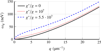
For nm, µm, kV/cm, and this gives . The corresponding µm-1 . Hence, the ripplon dispersion changes considerably at due to such a nonuniform electric field. Since at the trap bottom of UCN trap we do not need to hold liquid helium by a capillary effect, we may take a larger mm. Then, according to Eq. (22) this raises about times to . The corresponding ripplon dispersion, given by Eq. (17) without the last term but with renormalized ,
| (23) |
is shown in Fig. 4. It illustrates a considerable increase in ripplon energy at . Hence, theoretically, a nonuniform electric field may reduce the UCN inelastic scattering rate by thermally activated ripplons. However, a more thorough calculation is needed to study this effect quantitatively at a nonuniform gradient of the electric field strength.
V Possible trap designs
The voltage , corresponding to the required electric field and , depends on the geometry of electrodes. In the trap design of Fig. 5a with the trap radius a strong field kV/cm requires a voltage difference , which is too high. In the trap design shown in Figs. 5b,c the electric field and voltage do not depend on the trap radius but only on the distance from the grounded side wall to the electrode at .
The trap in Figs. 5b has only one toroidal electrode at placed at height cm above the helium level, i.e. just above the maximal height of UCN inside the trap. Then the distance depends on the height on the wall from the helium level. At large height , where the gravity energy to be compensated by electric field is the highest, the electric field is also the highest. Then Eq. (15) gives
| (24) |
which has a maximal value
| (25) |
at cm. At this heigh one can take [44] µm. Substituting this and to Eq. (25) we obtain kV , which is still very high and technically difficult. In Ref. [48] the realized voltage difference between two electrodes in 4He was only kV.
The required voltage can be reduced by an order of magnitude or more if one uses the trap design shown in Fig. 5c with several toroidal electrodes at placed at different heights above the helium level. If these toroidal electrodes are rather thin and placed at a small distance from the trap wall, theoretically, one can reduce the required voltage to only V. Technically, it may be more convenient to use the trap design illustrated in Fig. 5d, where thin wire electrodes hang down from the toroidal electrode above .
An electrode at height may produce additional inelastic scattering of UCN inside the trap. This electrode is always covered by a helium film of thickness due to the van-der-Waals forces, which attract helium vapor. However, for a save protection of UCN by this 4He film covering the electrodes we need . Such a thick 4He film can be hold by either the surface roughness and capillary effect [43, 44], described by Eq. (5), or by the electrostatic energy of 4He in electric field, given by Eq. (6). The latter is sufficient for a rather thin electrode. Indeed, the electric field around a cylindrical electrode of radius is . Hence, according to Eqs. (13) and (15), a commercially available copper wire of radius µm 222Bobbins with ultra thin copper wires of diameter µm are available for at www.amazon.com. at voltage placed at a distance µm = 0.2 mm from the grounded wall holds a 4He film of sufficient thickness if
or
| (26) |
For µm and mm this gives . Thus, a sufficient 4He coating of thin electrodes inside UCN trap is easy, because the voltage required for this coating is smaller than to hold 4He film of sufficient thickness on the side wall at height cm above helium level. The latter at requires kV/cm, which for the mm gives kV. Hence, theoretically, by using the trap design in Figs. 5c,d one may reduce the required voltage to only kV. Keeping two electrodes with voltage difference kV at a distance of only mm remains technically difficult. One can increase the distance between electrodes at the cost of increasing their voltage difference. A smaller voltage holds a thinner 4He film near the wall roughness edges, but it may still be useful to protect UCN from the absorption inside the trap walls.
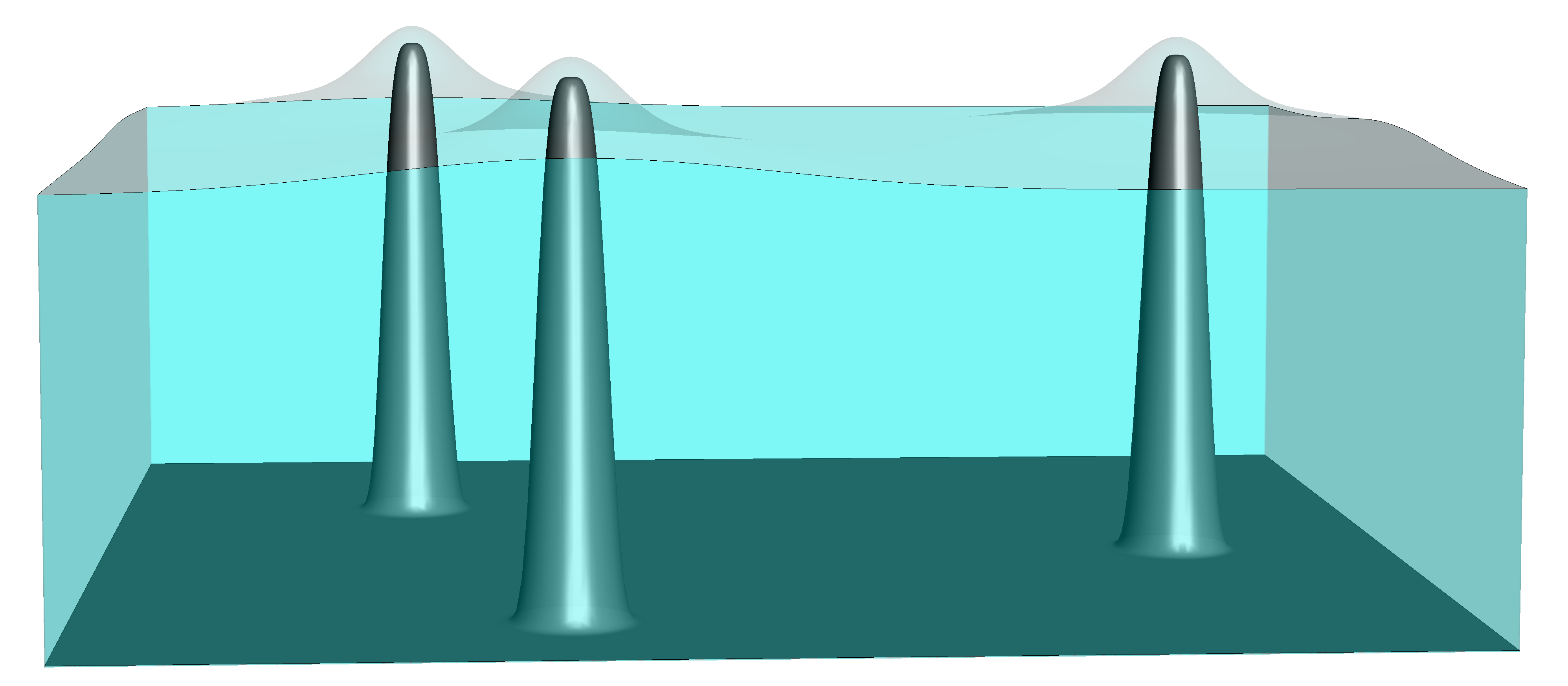
A 3D fur-like wall roughness with pyramidal or needle-shaped protrusions, as illustrated in Fig. 6, may further reduce the required voltage . The electric field at a distance from a needle-like electrode at voltage of curvature radius above another electrode in the form of a plane perpendicular to the needle and separated by the distance is [56]
| (27) |
Hence, in our case we have
| (28) |
For µm and nm, the required electric field at the surface kV/cm corresponds to the electric field far from the edge. If the second electrode is separated by a distance mm from the wall, the required voltage is V. However, making of such a wall with 3D fur-like roughness is more difficult than a cheap triangular diffraction grating, studied above.
VI Conclusions
To summarize, we propose to improve the material UCN traps by coating with liquid helium using the combined effect of capillarity and of electric field. The side wall roughness holds a sufficiently thick 4He film by the capillary effects [43, 44], but the very edges of this roughness remain coated by a too thin 4He film. If this rough wall serves as an electrode, the electric field is the strongest near these wall edges, which attracts 4He due to polarization forces. This helps to cover the wall edges and its entire surface by a sufficiently thick 4He film to completely protect UCN from the absorption inside trap walls. The second electrode, if made in the form of thin wires, may be placed inside the UCN trap because it get also coated by 4He and does not absorb neutrons. The strong nonuniform electric field on the helium surface increases the ripplon energy, which makes their equilibrium concentration smaller. This reduces the inelastic scattering rate of UCN by ripplons, but the effect is not sufficient to destroy this channel of UCN losses, which becomes dominating after the absorption of UCN inside trap walls is eliminated by their coating with liquid 4He. Fortunately, the neutron-ripplon interaction is weak, and the linear temperature dependence of UCN scattering rate by ripplons helps to accurately take this systematic error into account [42]. A low temperature K of trap walls is required to eliminate another source of UCN losses – scattering by helium vapor.
In spite of the mentioned technical difficulties, the proposed complete coating of UCN trap walls by liquid 4He may give rise to a new generation of ultracold neutron traps with a very long storage time. This may strongly improve the precision of neutron lifetime measurements and of other experiments with ultracold neutrons.
VII Acknowledgements
The work of P.D.G. is supported by the Russian Science Foundation grant # 23-22-00312. A.V.S. thanks the Foundation for the Advancement of Theoretical Physics and Mathematics ”Basis” for grant # 22-1-1-24-1. V.D.K. acknowledges the financial support from the NUST ”MISIS” grant No. K2-2022-025 in the framework of the federal academic leadership program Priority 2030. A.M.D. acknowledges the Ministry of Science and Higher Education of the Russian Federation (state assignment no. 0033-2019-0001 “Development of the Theory of Condensed Matter”).
References
- Abele [2008] H. Abele, Progress in Particle and Nuclear Physics 60, 1 (2008), https://www.sciencedirect.com/science/article/pii/S0146641007000622.
- Ramsey-Musolf and Su [2008] M. J. Ramsey-Musolf and S. Su, Physics Reports 456, 1 (2008), https://www.sciencedirect.com/science/article/pii/S0370157307003894.
- Dubbers and Schmidt [2011] D. Dubbers and M. G. Schmidt, Rev. Mod. Phys. 83, 1111 (2011), https://link.aps.org/doi/10.1103/RevModPhys.83.1111.
- Wietfeldt and Greene [2011] F. E. Wietfeldt and G. L. Greene, Rev. Mod. Phys. 83, 1173 (2011), https://link.aps.org/doi/10.1103/RevModPhys.83.1173.
- Gonzalez-Alonso et al. [2019] M. Gonzalez-Alonso, O. Naviliat-Cuncic, and N. Severijns, Progress in Particle and Nuclear Physics 104, 165 (2019), https://www.sciencedirect.com/science/article/pii/S0146641018300735.
- Liu et al. [2010] J. Liu, M. P. Mendenhall, A. T. Holley, H. O. Back, T. J. Bowles, L. J. Broussard, R. Carr, S. Clayton, S. Currie, B. W. Filippone, A. García, P. Geltenbort, K. P. Hickerson, J. Hoagland, G. E. Hogan, B. Hona, T. M. Ito, C.-Y. Liu, M. Makela, R. R. Mammei, J. W. Martin, D. Melconian, C. L. Morris, R. W. Pattie, A. Pérez Galván, M. L. Pitt, B. Plaster, J. C. Ramsey, R. Rios, R. Russell, A. Saunders, S. J. Seestrom, W. E. Sondheim, E. Tatar, R. B. Vogelaar, B. VornDick, C. Wrede, H. Yan, and A. R. Young (UCNA Collaboration), Phys. Rev. Lett. 105, 181803 (2010), https://link.aps.org/doi/10.1103/PhysRevLett.105.181803.
- Märkisch et al. [2019] B. Märkisch, H. Mest, H. Saul, X. Wang, H. Abele, D. Dubbers, M. Klopf, A. Petoukhov, C. Roick, T. Soldner, and D. Werder, Phys. Rev. Lett. 122, 242501 (2019), https://link.aps.org/doi/10.1103/PhysRevLett.122.242501.
- Sun et al. [2020] X. Sun, E. Adamek, B. Allgeier, Y. Bagdasarova, D. B. Berguno, M. Blatnik, T. J. Bowles, L. J. Broussard, M. A.-P. Brown, R. Carr, S. Clayton, C. Cude-Woods, S. Currie, E. B. Dees, X. Ding, B. W. Filippone, A. García, P. Geltenbort, S. Hasan, K. P. Hickerson, J. Hoagland, R. Hong, A. T. Holley, T. M. Ito, A. Knecht, C.-Y. Liu, J. Liu, M. Makela, R. Mammei, J. W. Martin, D. Melconian, M. P. Mendenhall, S. D. Moore, C. L. Morris, S. Nepal, N. Nouri, R. W. Pattie, A. Pérez Gálvan, D. G. Phillips, R. Picker, M. L. Pitt, B. Plaster, D. J. Salvat, A. Saunders, E. I. Sharapov, S. Sjue, S. Slutsky, W. Sondheim, C. Swank, E. Tatar, R. B. Vogelaar, B. VornDick, Z. Wang, W. Wei, J. W. Wexler, T. Womack, C. Wrede, A. R. Young, and B. A. Zeck (UCNA Collaboration), Phys. Rev. C 101, 035503 (2020), https://link.aps.org/doi/10.1103/PhysRevC.101.035503.
- Pospelov and Ritz [2005] M. Pospelov and A. Ritz, Annals of Physics 318, 119 (2005), https://www.sciencedirect.com/science/article/pii/S0003491605000539.
- Baker et al. [2006] C. A. Baker, D. D. Doyle, P. Geltenbort, K. Green, M. G. D. van der Grinten, P. G. Harris, P. Iaydjiev, S. N. Ivanov, D. J. R. May, J. M. Pendlebury, J. D. Richardson, D. Shiers, and K. F. Smith, Phys. Rev. Lett. 97, 131801 (2006), https://link.aps.org/doi/10.1103/PhysRevLett.97.131801.
- Serebrov et al. [2014] A. P. Serebrov, E. A. Kolomenskiy, A. N. Pirozhkov, I. A. Krasnoschekova, A. V. Vassiljev, A. O. Polushkin, M. S. Lasakov, A. K. Fomin, I. V. Shoka, V. A. Solovey, O. M. Zherebtsov, P. Geltenbort, S. N. Ivanov, O. Zimmer, E. B. Alexandrov, S. P. Dmitriev, and N. A. Dovator, JETP Letters 99, 4 (2014), https://doi.org/10.1134/S0021364014010111.
- Nesvizhevsky et al. [2002] V. V. Nesvizhevsky, H. G. Börner, A. K. Petukhov, H. Abele, S. Baeßler, F. J. Rueß, T. Stöferle, A. Westphal, A. M. Gagarski, G. A. Petrov, and A. V. Strelkov, Nature 415, 297 (2002), https://doi.org/10.1038/415297a.
- Jenke et al. [2014] T. Jenke, G. Cronenberg, J. Burgdörfer, L. A. Chizhova, P. Geltenbort, A. N. Ivanov, T. Lauer, T. Lins, S. Rotter, H. Saul, U. Schmidt, and H. Abele, Phys. Rev. Lett. 112, 151105 (2014), https://link.aps.org/doi/10.1103/PhysRevLett.112.151105.
- Golub et al. [1991] R. Golub, D. Richardson, and L. S. K., Ultra-Cold Neutrons (CRC Press, 1991) https://doi.org/10.1201/9780203734803.
- Ignatovich [1990] V. K. Ignatovich, The Physics of Ultracold Neutrons (Clarendon Press, 1990) https://isbnsearch.org/isbn/0198510152.
- Ignatovich [1996] V. K. Ignatovich, Physics-Uspekhi 39, 283 (1996), https://doi.org/10.1070/pu1996v039n03abeh000138.
- Serebrov et al. [2008] A. P. Serebrov, V. E. Varlamov, A. G. Kharitonov, A. K. Fomin, Y. N. Pokotilovski, P. Geltenbort, I. A. Krasnoschekova, M. S. Lasakov, R. R. Taldaev, A. V. Vassiljev, and O. M. Zherebtsov, Phys. Rev. C 78, 035505 (2008), https://link.aps.org/doi/10.1103/PhysRevC.78.035505.
- Arzumanov et al. [2015] S. Arzumanov, L. Bondarenko, S. Chernyavsky, P. Geltenbort, V. Morozov, V. V. Nesvizhevsky, Y. Panin, and A. Strepetov, Physics Letters B 745, 79 (2015), https://www.sciencedirect.com/science/article/pii/S0370269315002646.
- Serebrov et al. [2017] A. P. Serebrov, E. A. Kolomenskiy, A. K. Fomin, I. A. Krasnoschekova, A. V. Vassiljev, D. M. Prudnikov, I. V. Shoka, A. V. Chechkin, M. E. Chaikovskii, V. E. Varlamov, S. N. Ivanov, A. N. Pirozhkov, P. Geltenbort, O. Zimmer, T. Jenke, M. Van der Grinten, and M. Tucker, JETP Letters 106, 623 (2017), https://doi.org/10.1134/S0021364017220143.
- Serebrov et al. [2018] A. P. Serebrov, E. A. Kolomensky, A. K. Fomin, I. A. Krasnoshchekova, A. V. Vassiljev, D. M. Prudnikov, I. V. Shoka, A. V. Chechkin, M. E. Chaikovskiy, V. E. Varlamov, S. N. Ivanov, A. N. Pirozhkov, P. Geltenbort, O. Zimmer, T. Jenke, M. Van der Grinten, and M. Tucker, Phys. Rev. C 97, 055503 (2018), https://link.aps.org/doi/10.1103/PhysRevC.97.055503.
- Pattie, R. W. et al. [2019] Pattie, R. W., Callahan, N. B., Cude-Woods, C., Adamek, E. R., Adams, M., Barlow, D., Blatnik, M., D., Bowman, Broussard, L. J., Clayton, S., Currie, S., Dees, E. B., Ding, X., Fellers, D., Fox, W., Fries, E., Gonzalez, F., Geltenbort, P., Hickerson, K. P., Hoffbauer, M. A., Hoffman, K., Holley, A. T., Howard, D., Ito, T. M., Komives, A., Liu, C. Y., M., Makela, Medina, J., Morley, D., Morris, C. L., O’Connor, T., Penttilä, S.I., Ramsey, J.C., Roberts, A., Salvat, D., Saunders, A., Seestrom, S.J., Sharapov, E.I., Sjue, S.K.L., Snow, W.M., Sprow, A., Vanderwerp, J., Vogelaar, B., P.L., Walstrom, Wang, Z., Weaver, H., Wexler, J., Womack, T.L., Young, A.R., and Zeck, B.A., EPJ Web Conf. 219, 03004 (2019), https://doi.org/10.1051/epjconf/201921903004.
- Mampe et al. [1989] W. Mampe, P. Ageron, C. Bates, J. M. Pendlebury, and A. Steyerl, Phys. Rev. Lett. 63, 593 (1989), https://link.aps.org/doi/10.1103/PhysRevLett.63.593.
- Pichlmaier et al. [2010] A. Pichlmaier, V. Varlamov, K. Schreckenbach, and P. Geltenbort, Physics Letters B 693, 221 (2010), https://www.sciencedirect.com/science/article/pii/S0370269310009792.
- Huffman et al. [2000] P. R. Huffman, C. R. Brome, J. S. Butterworth, K. J. Coakley, M. S. Dewey, S. N. Dzhosyuk, R. Golub, G. L. Greene, K. Habicht, S. K. Lamoreaux, C. E. H. Mattoni, D. N. McKinsey, F. E. Wietfeldt, and J. M. Doyle, Nature 403, 62 (2000), https://doi.org/10.1038/47444.
- Leung et al. [2016] K. K. H. Leung, P. Geltenbort, S. Ivanov, F. Rosenau, and O. Zimmer, Phys. Rev. C 94, 045502 (2016), https://link.aps.org/doi/10.1103/PhysRevC.94.045502.
- Steyerl et al. [2017] A. Steyerl, K. K. H. Leung, C. Kaufman, G. Müller, and S. S. Malik, Phys. Rev. C 95, 035502 (2017), https://link.aps.org/doi/10.1103/PhysRevC.95.035502.
- Ezhov et al. [2018] V. F. Ezhov, A. Z. Andreev, G. Ban, B. A. Bazarov, P. Geltenbort, A. G. Glushkov, V. A. Knyazkov, N. A. Kovrizhnykh, G. B. Krygin, O. Naviliat-Cuncic, and V. L. Ryabov, JETP Letters 107, 671 (2018), https://doi.org/10.1134/S0021364018110024.
- Pattie et al. [2018] R. W. Pattie, N. B. Callahan, C. Cude-Woods, E. R. Adamek, L. J. Broussard, S. M. Clayton, S. A. Currie, E. B. Dees, X. Ding, E. M. Engel, D. E. Fellers, W. Fox, P. Geltenbort, K. P. Hickerson, M. A. Hoffbauer, A. T. Holley, A. Komives, C.-Y. Liu, S. W. T. MacDonald, M. Makela, C. L. Morris, J. D. Ortiz, J. Ramsey, D. J. Salvat, A. Saunders, S. J. Seestrom, E. I. Sharapov, S. K. Sjue, Z. Tang, J. Vanderwerp, B. Vogelaar, P. L. Walstrom, Z. Wang, W. Wei, H. L. Weaver, J. W. Wexler, T. L. Womack, A. R. Young, and B. A. Zeck, Science 360, 627 (2018), https://science.sciencemag.org/content/360/6389/627, https://science.sciencemag.org/content/360/6389/627.full.pdf .
- Nico et al. [2005] J. S. Nico, M. S. Dewey, D. M. Gilliam, F. E. Wietfeldt, X. Fei, W. M. Snow, G. L. Greene, J. Pauwels, R. Eykens, A. Lamberty, J. V. Gestel, and R. D. Scott, Phys. Rev. C 71, 055502 (2005), https://link.aps.org/doi/10.1103/PhysRevC.71.055502.
- Yue et al. [2013] A. T. Yue, M. S. Dewey, D. M. Gilliam, G. L. Greene, A. B. Laptev, J. S. Nico, W. M. Snow, and F. E. Wietfeldt, Phys. Rev. Lett. 111, 222501 (2013), https://link.aps.org/doi/10.1103/PhysRevLett.111.222501.
- Hirota et al. [2020] K. Hirota, G. Ichikawa, S. Ieki, T. Ino, Y. Iwashita, M. Kitaguchi, R. Kitahara, J. Koga, K. Mishima, T. Mogi, K. Morikawa, A. Morishita, N. Nagakura, H. Oide, H. Okabe, H. Otono, Y. Seki, D. Sekiba, T. Shima, H. M. Shimizu, N. Sumi, H. Sumino, T. Tomita, H. Uehara, T. Yamada, S. Yamashita, K. Yano, M. Yokohashi, and T. Yoshioka, Progress of Theoretical and Experimental Physics 2020, 10.1093/ptep/ptaa169 (2020), https://doi.org/10.1093/ptep/ptaa169, https://academic.oup.com/ptep/article-pdf/2020/12/123C02/35931162/ptaa169.pdf .
- Rajendran and Ramani [2021] S. Rajendran and H. Ramani, Phys. Rev. D 103, 035014 (2021), https://link.aps.org/doi/10.1103/PhysRevD.103.035014.
- Serebrov et al. [2021] A. P. Serebrov, M. E. Chaikovskii, G. N. Klyushnikov, O. M. Zherebtsov, and A. V. Chechkin, Phys. Rev. D 103, 074010 (2021), https://link.aps.org/doi/10.1103/PhysRevD.103.074010.
- Serebrov [2019] A. P. Serebrov, Physics-Uspekhi 62, 596 (2019).
- Dubbers et al. [2019] D. Dubbers, H. Saul, B. Märkisch, T. Soldner, and H. Abele, Physics Letters B 791, 6 (2019).
- Goremychkin and Pokotilovski [2017] E. A. Goremychkin and Y. N. Pokotilovski, JETP Letters 105, 548 (2017).
- Golub et al. [1983] R. Golub, C. Jewell, P. Ageron, W. Mampe, B. Heckel, and I. Kilvington, Zeitschrift für Physik B Condensed Matter 51, 187 (1983).
- Bokun [1984] R. C. Bokun, Sov. J. Nucl. Phys. 40, 287 (1984), https://inis.iaea.org/search/searchsinglerecord.aspx?recordsFor=SingleRecord&RN=16073419.
- Alfimenkov et al. [2009] V. P. Alfimenkov, V. K. Ignatovich, L. P. Mezhov-Deglin, V. I. Morozov, A. V. Strelkov, and T. M. I., Communications of Joint Institute for Nuclear Research, Dubna preprint (in Russian) P3-2009-197 (2009), http://www1.jinr.ru/Preprints/2009/197(P3-2009-197).pdf.
- Ahmed et al. [2019] S. Ahmed, E. Altiere, T. Andalib, B. Bell, C. P. Bidinosti, E. Cudmore, M. Das, C. A. Davis, B. Franke, M. Gericke, P. Giampa, P. Gnyp, S. Hansen-Romu, K. Hatanaka, T. Hayamizu, B. Jamieson, D. Jones, S. Kawasaki, T. Kikawa, M. Kitaguchi, W. Klassen, A. Konaka, E. Korkmaz, F. Kuchler, M. Lang, L. Lee, T. Lindner, K. W. Madison, Y. Makida, J. Mammei, R. Mammei, J. W. Martin, R. Matsumiya, E. Miller, K. Mishima, T. Momose, T. Okamura, S. Page, R. Picker, E. Pierre, W. D. Ramsay, L. Rebenitsch, F. Rehm, W. Schreyer, H. M. Shimizu, S. Sidhu, A. Sikora, J. Smith, I. Tanihata, B. Thorsteinson, S. Vanbergen, W. T. H. van Oers, and Y. X. Watanabe (TUCAN Collaboration9), Phys. Rev. C 99, 025503 (2019), https://link.aps.org/doi/10.1103/PhysRevC.99.025503.
- Zimmer [2016] O. Zimmer, Phys. Rev. C 93, 035503 (2016), https://link.aps.org/doi/10.1103/PhysRevC.93.035503.
- Grigoriev et al. [2016] P. D. Grigoriev, O. Zimmer, A. D. Grigoriev, and T. Ziman, Phys. Rev. C 94, 025504 (2016), https://link.aps.org/doi/10.1103/PhysRevC.94.025504.
- Grigoriev and Dyugaev [2021] P. D. Grigoriev and A. M. Dyugaev, Phys. Rev. C 104, 055501 (2021).
- Grigoriev et al. [2021] P. D. Grigoriev, A. M. Dyugaev, T. I. Mogilyuk, and A. D. Grigoriev, JETP Letters 114, 493 (2021).
- Note [1] Diffraction gratings with the period µm and dimensions are available at a price of at www.amazon.com.
- Kulin et al. [2016] G. V. Kulin, A. I. Frank, S. V. Goryunov, P. Geltenbort, M. Jentschel, V. A. Bushuev, B. Lauss, P. Schmidt-Wellenburg, A. Panzarella, and Y. Fuchs, Phys. Rev. A 93, 033606 (2016).
- Kulin et al. [2019] G. Kulin, A. Frank, M. Zakharov, S. Goryunov, V. Bushuev, A. Panzarella, P. Geltenbort, and M. Jentschel, Journal of Experimental and Theoretical Physics 129, 806 (2019).
- Ito et al. [2016] T. M. Ito, J. C. Ramsey, W. Yao, D. H. Beck, V. Cianciolo, S. M. Clayton, C. Crawford, S. A. Currie, B. W. Filippone, W. C. Griffith, M. Makela, R. Schmid, G. M. Seidel, Z. Tang, D. Wagner, W. Wei, and S. E. Williamson, Review of Scientific Instruments 87, 045113 (2016), https://doi.org/10.1063/1.4946896 .
- Binns and Lawrenson [1973] K. Binns and P. Lawrenson, Analysis and Computation of Electric and Magnetic Field Problems, Pergamon international library of science, technology, engineering, and social studies (Elsevier Science & Technology, 1973).
- Volodin et al. [1977] A. P. Volodin, M. S. Khaikin, and V. S. Edelman, JETP Letters 26, 543 (1977).
- Leiderer [1992] P. Leiderer, Journal of Low Temperature Physics 87, 247 (1992).
- Ito et al. [2012] T. M. Ito, S. M. Clayton, J. Ramsey, M. Karcz, C.-Y. Liu, J. C. Long, T. G. Reddy, and G. M. Seidel, Phys. Rev. A 85, 042718 (2012).
- Phan et al. [2020] N. S. Phan, V. Cianciolo, S. M. Clayton, S. A. Currie, R. Dipert, T. M. Ito, S. W. T. MacDonald, C. M. O’Shaughnessy, J. C. Ramsey, G. M. Seidel, E. Smith, E. Tang, Z. Tang, and W. Yao, Phys. Rev. C 102, 035503 (2020).
- Mel’nikovskii and Kriminskii [1997] L. A. Mel’nikovskii and S. A. Kriminskii, Journal of Experimental and Theoretical Physics 84, 758 (1997).
- Note [2] Bobbins with ultra thin copper wires of diameter µm are available for at www.amazon.com.
- Florkowska and Wlodek [1993] B. Florkowska and R. Wlodek, IEEE Transactions on Electrical Insulation 28, 932 (1993).