A \DeclareNewFootnoteB
Benchmarking and Security Considerations
of Wi-Fi FTM for Ranging in IoT Devices
Abstract
The IEEE 802.11mc standard introduces fine time measurement (Wi-Fi FTM), allowing high-precision synchronization between peers and round-trip time calculation (Wi-Fi RTT) for location estimation – typically with a precision of one to two meters. This has considerable advantages over received signal strength (RSS)-based trilateration, which is prone to errors due to multipath reflections. We examine different commercial radios which support Wi-Fi RTT and benchmark Wi-Fi FTM ranging over different spectrums and bandwidths. Importantly, we find that while Wi-Fi FTM supports localization accuracy to within one to two meters in ideal conditions during outdoor line-of-sight experiments, for indoor environments at short ranges similar accuracy was only achievable on chipsets supporting Wi-Fi FTM on wider (VHT80) channel bandwidths rather than narrower (HT20) channel bandwidths. Finally, we explore the security implications of Wi-Fi FTM and use an on-air sniffer to demonstrate that FTM messages are unprotected. We consequently propose a threat model with possible mitigations and directions for further research.
keywords:
Wi-Fi, IEEE 802.11mc, Ranging, Localization1 Introduction
The fine time measurement (Wi-Fi FTM) and round-trip-time Wi-Fi RTT features of the IEEE 802.11mc amendment to the Wi-Fi standard allow supporting devices to estimate the distance to other devices supporting Wi-Fi FTM ranging. This capability is supported in various modes (Station (STA), Access Point (AP), and Neighborhood Aware Networking (NAN)) and allows applications to benefit from accurate localization and context awareness in use-cases such as asset tracking, geofencing, industrial robotics, home automation control, and location-based information for service broadcasting.
Traditionally, distance ranging based on the Received Signal Strength Indicator (RSSI), which estimates the power of the received signal as measured through the hardware, is a simple and extensively adopted means for estimating distance – often employing a straightforward long-distance path loss model [zafari2019survey],
| (1) |
| FTM parameters | Description |
|---|---|
| Frequency band | 6GHz/5GHz has better accuracy in comparison to 2.4GHz due to available bandwidth. |
| Channel bandwidth | Ranging error roughly halves with double bandwidth, when comparing the 20/40/80/160 MHz frequency bands. |
| Antenna diversity | Multiple antennas reduce ranging error due to better diversity. 2x2 configuration has approx 30 percent better accuracy. |
| Multipath | Line-of-sight path is preferred for the best accuracy. |
| Tx power | Higher transmission power allows for minimizing the errors when used within the regulatory limit. |
| Timestamping | Hardware time stamping clock resolution and lower ppm errors allow better accuracy. |
where is the RSSI at the reference distance and is a path loss exponent. While this method is easy to employ, due to multipath issues the accuracy is frequently poor as the relationship between RSSI and distance is non-linear and is adversely affected by obstacles in non line-of-sight environments. In contrast, precise time measurement provided by Wi-Fi FTM, Wi-Fi RTT calculates the distance between two devices by measuring the time a packet takes to make a round trip (i.e., the time taken for an initiating device to receive an acknowledgment from a neighbor after transmitting a packet to that neighbor). The difference between the transmit and receive time stamps denotes the flight time which, when taking into account the speed of light, indicates how far away the Wi-Fi RTT initiator device is from the Wi-Fi RTT responder device. Importantly, RTT measurement errors are linear with distance, not exponential like RSSI, allowing sub-meter accuracy. However, precise time-stamping of packets supported by Wi-Fi FTM is highly dependent on the hardware capabilities, such as the clock resolution. Additionally, path First Arrival Correction (FAC) and accurate time-stamping of the first packet symbol are also key contributors to Wi-Fi RTT accuracy. The aim of this work is to therefore evaluate the capabilities of different commercial off-the-shelf (COTS) hardware platforms supporting the Wi-Fi FTM protocol and comparing the ranging accuracy across different bandwidth configurations.
Our contributions. In this paper we identify a number of commercially available Wi-Fi chipsets which support Wi-Fi FTM ranging and benchmark the accuracy in both outdoor and indoor experimental setups.
Outline of this paper. In Section 2 we provide necessary preliminaries on the operation of Wi-Fi RTT and Wi-Fi FTM. In Section 3 we provide details of our experimental setup and perform benchmarking of three commercially available Wi-Fi FTM chipsets. We explore related localization technologies in Section LABEL:sec:related_work before concluding in Section LABEL:sec:conclusions.
2 Ranging with Wi-Fi FTM
Wi-Fi FTM was introduced in the IEEE 802.11-2016 standard revision for the purpose of allowing a fine timing measurement (FTM) frame to calculate round-trip time (RTT) between two peers. Specifically, Wi-Fi RTT makes use of IEEE 802.11 frame exchange based on acknowledgment frames (as per Figure 1(a)) as well as FTM bursts (as per Figure 1(b)), which further allows delivering many FTM messages consecutively while lowering timing computation error by averaging multiple timestamps.
In both instances, an FTM request frame (FTMR) is provided by the FTM initiator to start the process, while the FTM responder has the option of accepting it or rejecting the FTMR. Upon acceptance, the responder sends an acknowledge (ACK) frame. The responder then sends a single FTM frame, recording the current time within the frame, to start the beginning of the round-trip measurement. As soon as the preamble is detected by the initiator, it starts recording time at time . The FTM initiator then creates its own ACK frame and transmits it to the responder. The ACK frame is transmitted at the initiator, which accounts for the hardware signal processing delay of the initiator’s digital baseband and radio front end. Furthermore, the responder can determine the overall round-trip time of the signal, as per Equation 2, by deducting from when it receives the initiator’s ACK frame at time and adding this to the delta between and .
| (2) |
The time a WiFi signal takes to travel over the air between the RTT initiator peer and the RTT responder peer is proportional to the actual distance between them (approximately 3.3 nanoseconds per meter). Accordingly, the distance between the peers can be estimated using Equation 3.
| (3) |


| Configuration | Initiator | Responder | Specification | Channel | Bursts | FTM Ranging |
|---|---|---|---|---|---|---|
| Config. 1 | Google Pixel 4a (WCN3990) | Google Wi-Fi Mesh AP (QCA4019) | VHT80 | 5745MHz | 8 | Native |
| Config. 2 | FeatherS2 NEO (ESP32-S2) | FeatherS2 NEO (ESP32-S2) | HT20 | 2412MHz | 2 | Native |
| Config. 3 | Google Pixel 4a (WCN3990) | Google Pixel 4a (WCN3990) | HT20 | 2412MHz | 8 | Wi-Fi Aware |
However, in some circumstances (e.g., due to environmental factors such as temperature [boano2014templab]) the internal clock between the initiator peer with the responder peer may not be synchronized, hence direct subtraction can not be done with two timestamps to calculate RTT. The difference in timestamps when the signal travels in the reverse direction is affected in the opposite way by the clock offset between peers. As a result, the round trip time (RTT) can be obtained without having to know the clock offsets, by simple addition and subtraction of four timestamps (as per Equation 3).
Fundamentally, however, localization accuracy depends not only on the accuracy of the timestamp but also on numerous other factors. The bandwidth, antenna diversity, the transmit power of the broadcasting device, and the reception sensitivity of the receiving device are also key factors of a Wi-Fi radio that define the accuracy of its individual measurements in an RF ranging system.
Bandwidth. In a wireless system, preamble detection is used to determine the beginning of a frame. Hardware timestamping systems based on preamble detection present a resolution bound equal to the baseband sampling period, on which the FTM protocol depends. Indeed, a detection delay of as little as 1 ns could result in an error of 30 cm (3). Hence, high resolution of the time-stamping clock is required as FTM requires pico second clock resolution for time-stamping. As the sampling period is inverse of the bandwidth (either 20MHz, 40MHz, or 80MHz), better resolution can be achieved at higher bandwidths (as per the Nyquist rate , where is the sampling frequency and is the bandwidth in MHz).
Antenna diversity. Having multiple antennas helps to extract the spatial diversity (transmitting multiple copies of the same information via multiple antennas) which provides more resilient transmissions, and also helps to save the system from undergoing deep fade events.
Multipath. Furthermore, the channel frequency response of the associated channel varies owing to the multipath propagation. Specifically, multiple copies of the same signal with different amplitudes and phases arrive at the receiver due to the interaction of the signal with the surrounding objects. Also, due to the multipath propagation, the antenna receives several copies of the transmitted signals that have been subjected to various delays and attenuation. In the frame detector, these reflections can cause a sizable amount of jitter, especially in non-line-of-sight circumstances. FTM accuracy relies on the first arrival correction algorithm due to the multipath behavior, which is generally implemented in the lower MAC of the firmware component.
Timestamping. The coherence time, which specifies the period of time during which the channel is thought to be invariant, describes the dynamic of the channel. This channel variation may cause inaccuracy in the estimation of the channel delay due to the non-stationary state and, as a result, it will affect the FTM accuracy. With mobility, the accuracy can further suffer as the involved nodes’ mobility may incur more estimation errors. Finally, with chipsets such as the WCN3990 in the Google Pixel 4a including Wi-Fi FTM ranging functionality as part of the Wi-Fi Aware specification, there has been little study on Wi-Fi FTM performance when being used as part of a wider standard rather than a ‘native’ approach where the FTM functions are accessed directly.
3 Experimental Analysis

To date, there are few examples of commercial Wi-Fi chipsets which support Wi-Fi FTM. In Table 2 we identify three compliant chipsets and indicate the supported channel bandwidth specification, the channel frequency used in experiments, the number of Wi-Fi FTM bursts supported, and whether Wi-Fi FTM ranging is directly accessible in the firmware or is included as part of Wi-Fi Aware.
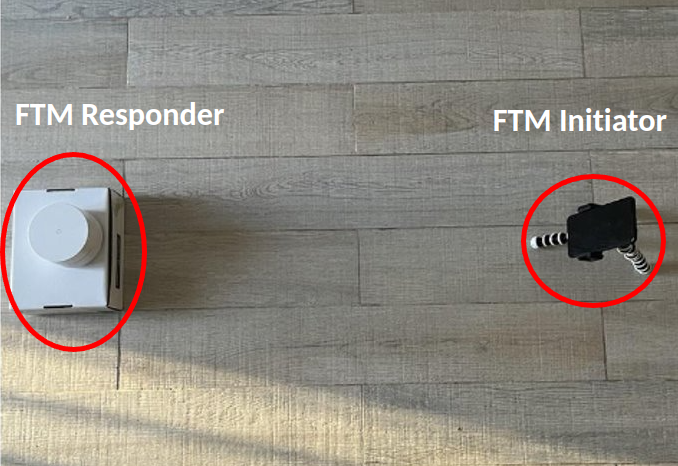
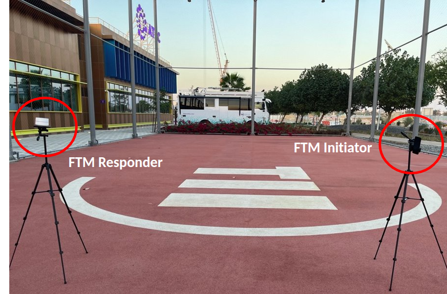
Specifically, we consider the WCN3990 on a Google Pixel 4a, the QCA4019 on a Google Wi-Fi Mesh AP, and the ESP32-S2 on the FeatherS2 NEO and benchmark these devices in both an indoor (short range) and outdoor (longer range) experimental setup (Figure 2). Both setups consider a line-of-sight (LOS) scenario with only two devices, an initiator device, and a responder device. As per Figure 2(c), in the indoor experimental setup the devices were placed on the ground and separated at distances of 0.5, 1.0, and 1.5 meters, while in the outdoor experimental setup, the devices were placed on tripods in an open area and separated at 3.0, 5.0, and 10.0 meters.
Only the ESP32-S2 and WCN3990 support both and modes allowing us to use the same device for the initiator and responder; when using ‘Native’ Wi-Fi FTM ranging on the ESP32-S2 and using Wi-Fi Aware on the WCN3990. Unfortunately, in this configuration, these devices are limited to 2.4GHz and HT20 (20MHz channel bandwidth). However, by employing a Google Wi-Fi Mesh AP (QCA4019) for the responder and the WCN3990 for the initiator (allowing one to use ‘Native’ mode rather than Wi-Fi Aware), it is possible to perform Wi-Fi FTM ranging at 5GHz on VHT80 (80MHz channel bandwidth). These configurations are summarized in Table 2, and all experimental results are presented in Figure 3.
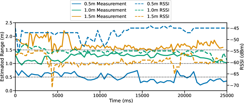
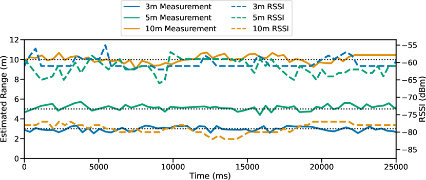
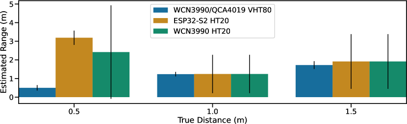
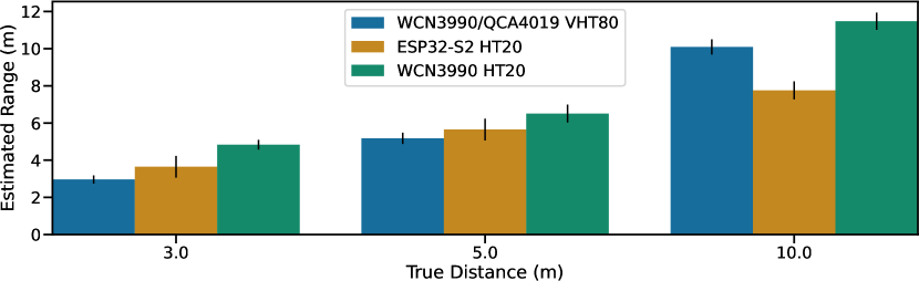
Config 1 (VHT80 + ‘native’ ranging). The first configuration uses a Google Pixel 4a (WCN3990) as initiator STA and a Google Wi-Fi MESH AP (QCA4019) as responder the responder AP. The Wi-Fi baseband in both chipsets supports IEEE 802.11ac with VHT80, allowing testing of Wi-Fi FTM ranging over a wider (80MHz) channel bandwidth. From Figure 3 it can be seen that for both the indoor and outdoor setups the WCN3990 manages to estimate the distance to the responder with sub-meter accuracy at all distances, and a small standard deviation.
Config 2 (HT20 + ‘native’ ranging). The second configuration employs two FeatherS2 NEO (ESP32-S2) boards as both initiator (STA) and responder (AP) devices. The ESP32-S2 can be clocked at up to 240 MHz in 2.4 GHz HT40 mode, however Wi-Fi FTM ranging is only supported on HT20