Theory for charge density wave and orbital-flux state in antiferromagnetic kagome metal FeGe
Abstract
In this work, we theoretically study the charge order and orbital magnetic properties of a new type of antiferromagnetic kagome metal FeGe. Based on first principles density functional theory (DFT) calculations, we have studied the electronic structures, Fermi-surface quantum fluctuations, as well as phonon properties of the antiferromagnetic kagome metal FeGe. We find that charge density wave emerges in such a system due to a subtle cooperation between electron-electron (-) interactions and electron-phonon couplings, which gives rise to an unusual scenario of interaction-triggered phonon instabilities, and eventually yields a charge density wave (CDW) state. We further show that, in the CDW phase, the ground-state current density distribution exhibits an intriguing star-of-David pattern, leading to flux density modulation. The orbital fluxes (or current loops) in this system emerges as a result of the subtle interplay between magnetism, lattice geometries, charge order, and spin-orbit coupling (SOC), which can be described by a simple, yet universal, tight-binding theory including a Kane-Mele type SOC term and a magnetic exchange interaction. We further study the origin of the peculiar step-edge states in FeGe, which shed light on the topological properties and correlation effects in this new type of kagome antiferromagnetic material.
The frustrated nature of a kagome lattice can give rise to intriguing electronic structure such as flat bands, Dirac cones, and van Hove singularities (vHS) Bergman et al. (2008); Zhou et al. (2017); Neupert et al. (2022); Yin et al. (2022). The flat bands may serve as a good platform for strongly correlated physics such as quantum magnetism and unconventional superconductivity Tang et al. (2011); Kiesel et al. (2013a); Wang et al. (2013); Kiesel and Thomale (2012); Yu and Li (2012); Yin et al. (2018a); Ye et al. (2018a); Liu et al. (2018a); Yin et al. (2020); Ko et al. (2009); Balents (2010); Kiesel et al. (2013b). The Dirac points can be gapped out either by spontaneous time-reversal symmetry breaking or spin-orbit coupling (SOC), which thus exhibits nontrivial topological properties Yin et al. (2018b); Ye et al. (2018b); Xu et al. (2015). When the Fermi level is tuned to the van Hove singularity of a kagome metal, various correlated states may emerge through the Fermi-surface nesting scenario as driven by - Coulomb interactions Wu et al. (2021a); Feng et al. (2021); Gu et al. (2021); Park et al. (2021); Ortiz et al. (2020); Jiang et al. (2021a); Zhao et al. (2021); Ortiz et al. (2021a); Chen et al. (2021a, b); Yu et al. (2021a); Xu et al. (2021); Yin et al. (2021); Li et al. (2021); Zhang et al. (2021); Ortiz et al. (2021b); Wu et al. (2021b); Kang et al. (2021); Yu et al. (2021b); Nakayama et al. (2021); Li et al. (2022a); Liu et al. (2021); Cho et al. (2021); Zhou et al. (2021); Xie et al. (2022); Wulferding et al. (2021); Wang et al. (2021); Song et al. (2021); Nie et al. (2022); Mielke et al. (2022); Lou et al. (2022); Li et al. (2022b); Wu et al. (2022); Shan et al. (2022).
Recently, scanning tunnelling microscopy (STM) and muon spin relaxation (sR) measurements reveal time-reversal breaking charge orders in AV3Sb5 (A=K, Rb, Cs) Jiang et al. (2021b); Mielke et al. (2022); Yu et al. (2021b); Shan et al. (2022), which emerge at temperatures near or below the CDW transitions for this class of materials. Interestingly, these time-reversal breaking CDW phases are proposed to exhibit spontaneous real-space current loops, and are associated with orbital flux patterns Varma (1997); Liu et al. (2016); Liu and Dai (2021); Bourges et al. (2021); Feng et al. (2021); Denner et al. (2021); Ma and Liu (2021). Moreover, recent experimental studies demonstrate that an antiferromagnetic metal FeGe with kagome lattice structure also hosts a 22 charge order Yin et al. (2022); Teng et al. (2022a), which is closely correlated with the antiferromagnetism Teng et al. (2022b); Miao et al. (2022). Despite different theoretical proposals Shao et al. (2022); Zhou et al. (2022); Wu et al. (2023), the origin of CDW state and how the charge order interplays with antiferromagnetism in FeGe are still open questions. In this work we theoretically study the properties of charge density wave and the orbital-flux states in the antiferromagnetic kagome metal FeGe. Based on first principles DFT calculations, we have systematically studied the electronic structures, Fermi-surface quantum fluctuations, and phonon properties of FeGe. Specifically, through generalized susceptibility calculations within random phase approximation (RPA), we find that - interactions along cannot drive any CDW-type instability in FeGe. However, - interactions would renormalize the effective mass around the Fermi surface which thus enhances the density of states contributed by Ge orbitals. The latter is coupled with a branch of low-frequency optical phonon modes around point, which are consisted of Ge atomic displacements. This branch of Ge phonon modes is getting softer with the increase of as more and more Ge orbitals contribute to the Fermi surface, and eventually gets frozen with the onset of CDW. Therefore, we propose that the CDW state in FeGe is triggered by an interaction-assisted phonon instability.
We further show that, in the CDW phase, the inter-site currents in the ground state form a mutually intercalated star-of-David and double-triangular current pattern. Such orbital fluxes (or current loops) in this system emerges as a result of the subtle interplay between magnetism, lattice geometries, charge order, and spin-orbit coupling (SOC), which can be described by a simple, yet universal, tight-binding model including a Kane-Mele type SOC term and a magnetic exchange interaction. Moreover, we have also studied FeGe in the monolayer form in the CDW phase, which turns out to be a topological metal with both Weyl points and flat Chern band near the Fermi level, exhibiting multiple low-energy edge states. This naturally explains the origin of the recently observed spin polarized step-edge states in FeGe.
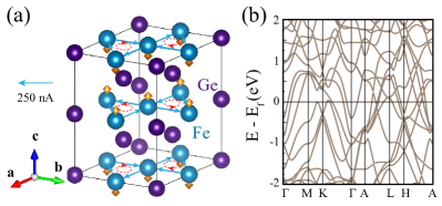
FeGe consists of an alternating stacking of the Fe3Ge kagome layer and the Ge honeycomb layer as shown in Fig. 1(a). It has an -type collinear antiferromagnetic order along the axis which doubles the primitive cell with a Néel temperature K Bernhardt and LebechS (1984). We perform DFT calculations with additional Hubbard-like on-site interactions applied to the Fe orbitals Liechtenstein et al. (1995), where the Hubbard is treated as a parameter to be varied. With eV (determined through the linear-response method Cococcioni and de Gironcoli (2005)) and Hund’s coupling eV, the calculated local magnetic moment for each Fe atom is 2.61 . The band structures in the antiferromagnetic phase of the pristine structure are shown in Fig. 1(b), which involve multiple bands around the Fermi level. Moreover, these low-energy bands are topologically nontrivial, which host multiple Dirac nodal loops as marked by the green circles in Fig. S5 in Supplementary Information (SI). The nodal loops are resided within the plane, which are protected by horizontal mirror symmetry (sup, ). More details about the band topology are given in SI sup .
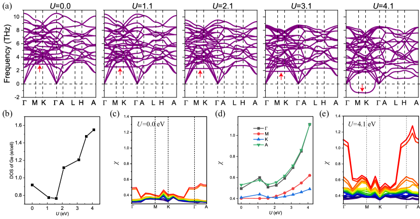
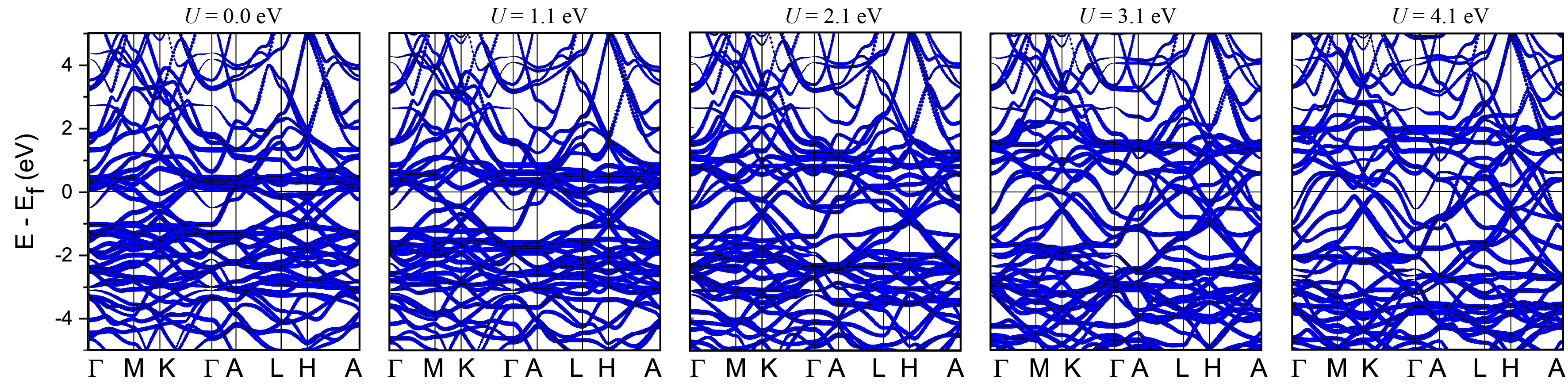
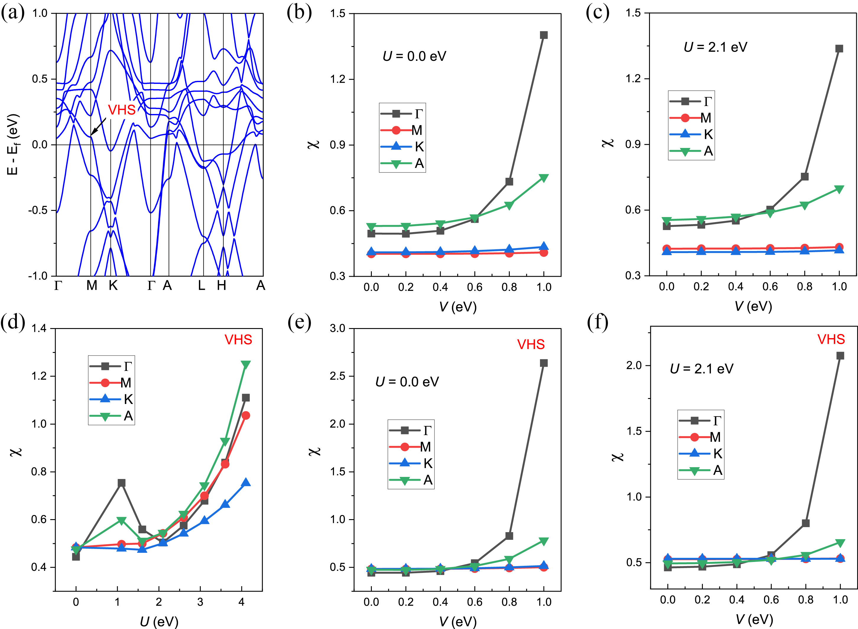
We continue to discuss the origin of the CDW phase in FeGe. Recent experiments report an in-plane 22 charge order at temperatures below K in FeGe, which seems to be interwined with its antiferromagnetic order Yin et al. (2022). To shed light on the experiments, we first calculate the phonon spectra of pristine FeGe at different Hubbard values, the results are shown in Fig. 2(a). As we can see, at small , the phonon spectrum of the pristine structure are well behaved without any imaginary frequency, indicating that the pristine structure is stable. With the increase of value, a flat phonon band within the plane, as marked by red arrow in Fig. 2(a), gradually moves downward in frequency and becomes imaginary when eV, indicating that the pristine structure eventually gets unstable at larger values, possibly with the onset of CDW. A closer inspection reveals that the soft branch of phonon modes are contributed by collective displacements of the Ge atoms. This unusual dependence of the phonon spectrum on the Hubbard implies that the CDW transition in FeGe may be triggered by - interactions. It turns out that with the increase of , the flat bands contributed from the Fe 3 orbitals are gradually pushed away from the Fermi level (see Supplementary Information); in the meanwhile, contributions from the Ge orbitals at the Fermi level become more and more significant (Fig. 2(b)) with the increase of . As the soft phonon band (marked in Fig. 2(a)) is contributed by Ge displacements, it is coupled to the Ge 4 orbitals much more strongly than to the Fe orbitals. Thus, an enhancement of the Ge spectral weight at the Fermi surface would yield stronger electron-phonon coupling matrix elements for the soft phonon band with the Ge displacements. This would give rise to a strong renormalization effects to the phonon frequency Giustino (2017), and eventually makes the soft phonon band (from Ge displacements) unstable, driving the CDW transition. Such an argument is also consistent with the relaxed structure of the CDW phase as shown in Fig. 3(a), in which only the Ge atoms show substantial distortions. We will discuss this in greater details later.
We note that the Hubbard value can be calculated self consistently through the response process of local charge density to a perturbative potential Cococcioni and de Gironcoli (2005), which gives eV for Fe orbitals. This justifies the above argument that CDW of FeGe may be induced through an interaction-assisted phonon instability scenario. Certainly DFT+ is a mean-field approach which cannot fully capture the characteristics of single-particle excitation spectrum for such correlated metals Ḣowever, recently both angle resolved photoemission spectroscopy (ARPES) measurements Teng et al. (2022b) and DFT + dynamical mean field theory (DMFT) calculations Miao et al. (2022) suggest an overall effective mass renormalization by a factor of 1.6 compared to DFT band structures, with well defined quasi-particle features around Fermi level. As the Fermi surface has contributions from both Fe and Ge orbitals, both the overall density of states (DOS) and Ge DOS around the Fermi level would be enhanced due to - interaction effects. This further confirms the above scenario that interaction-enhanced DOS would lead to stronger electron-phonon coupling effects thus induces phonon instability.
We also consider the possibility that the CDW state in antiferromagnetic FeGe may be driven by Fermi-surface instabilities due to strong - interaction effects. We calculate the general susceptibility tensor defined in the charge-sublattice-orbital-spin space Liu and Balents (2017); Uehara et al. (2015); Qiu et al. (2021); Ma et al. (2022) based on a realistic Wannier tight binding model including all the Fe orbitals and Ge orbitals generated from DFT calculations. The eigenmodes and eigenvalues of the static susceptibility tensor reflect the properties of the intrinsic quantum fluctuations at the Fermi surface. The - interaction renormalization effects on the generalized susceptibility tensor are treated by random phase approximation (RPA). The leading eigenmodes of the RPA generalized susceptibility tensor indicate the possible spontaneous symmetry breaking states driven by Fermi surface quantum fluctuations and - interactions. The details are given in Supplementary Information. In Fig. 2(d), we show the eigenvalues of the bare susceptibility tensor calculated from the Fermi surface in the antiferromagnetic ground state of FeGe with pristine lattice structure. We see that the eigenvalues of all the leading Fermi-surface fluctuation modes are small, with amplitudes . Including - interactions in the RPA framework does not change the result qualitatively. As shown in Fig. 2(e), the largest eigenvalues of the RPA susceptibility tensor at different high-symmetry points (, , , ) only show moderate enhancement with the increase of , which are far from driving a CDW transition (marked by diverging susceptibility eigenvalue). We have further inspected the effects of inter-site Coulomb interactions (between Fe and Ge electrons), and still cannot find any instability mode that can lead to CDW state (see supplementary information). Therefore, we conclude that in FeGe - interactions alone cannot lead to a CDW-type Fermi surface instability; rather the CDW state results from a subtle interplay between on-site - interactions and electron-phonon couplings, which realizes an intriguing scenario of interaction-assisted phonon instability, giving rise to the CDW state.
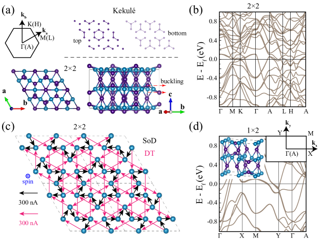
As the phonon spectrum at eV has a whole optical-phonon branch with imaginary frequencies within the plane (Fig. 2), which implies that there could be various possible lattice distortions. Here we only consider the unstable phonon modes at the three points in the pristine Brillouin zone, which are the modes that first become unstable as increases. We first make a linear combination of the three unstable phonon modes at the three points, which yield a supercell structure. Then we take such a lattice distortion as an initial ansatz for the structural relaxation calculation. In Fig. 3(a) we present the fully relaxed lattice structure of a supercell, which preserves all the symmetries of the pristine structure. This is a stable structure as no more imaginary frequency can be found in its phonon spectrum as shown in Fig. S6 in SI sup . Such a CDW phase involves two types of lattice distortions. The first one is a type of in-plane shortening or elongation of the nearest neighbour Ge-Ge bond within the honeycomb Ge layer, which forms a “kekulé type” distortion pattern of the Ge honeycomb lattice as shown in the top panel of Fig. 3(a), where the two Ge atoms connected by a solid line denotes the shortened Ge-Ge bond, consistent with previous report Shao et al. (2022). The kekulé distortions of the two Ge honeycomb layers within an antiferromagnetic primitive cell stacks along the direction in an anti-phase way as illustrated by the opposite kekulé distortions for the bottom and top Ge layers [top panel of Fig. 3(a)]. The second type of distortion is the out-of-plane buckling of the Ge atoms within the Fe kagome plane, as shown in the bottom panel of Fig. 3(a). We have also considered the situation that only one of the three unstable phonon modes at the points is stablized and leads to a CDW phase with supercell, whose relaxed lattice structure is shown in the inset of Fig. 3(d). Although the supercell is slightly lower in energy than the one, the former is inconsistent with recent experimental observations Yin et al. (2022); Teng et al. (2022c). Thus, the CDW phase observed in experiments may be the supercell resulted from the spontaneous condensation of three unstable phonon modes at the three points, which are characterized by in-plane kekulé distortions and out-of-plane bucklings of the Ge atoms.
We then turn to the discussion of the electronic structures and orbital magnetic properties of antiferromagnetic FeGe within the CDW phase. In Fig. 3(b) we present the band structures of the antiferromagnetic FeGe in the lattice structure, where every band is twofold degenerate due to the combined time-reversal () and inversion symmetry of the antiferromagnetic phase.As mentioned above, a realistic Wannier tight-binding model including all the Fe orbitals and Ge orbitals has been constructed for the antiferromagnetic CDW phase, based on which the inter-site currents have been calculated. As denoted by the arrows in Fig. 3(c), the current pattern of the Fe kagome layer with spin up magnetization in the CDW phase is qualitatively different from that of the pristine phase (Fig. 1(a)). In the pristine phase of the antiferromagnetic state, the currents flow around a loop connecting the nearest-neighbor Fe triangle within the kagome plane, with the current amplitude nA. In the CDW phase, as a result of the lattice distortion, the current pattern within each Fe kagome layer consists of two types of current loops: the first one only flows between the nearest neighbor Fe sites, forming a star of David (SoD) current loop flowing in the clockwise direction (black arrows in Fig. 3(c)) with the current amplitude 360 nA; the second type only flows between the second nearest neighbor Fe sites, forming double triangular shaped (DT) current loops flowing in the counter-clockwise direction (red arrows in Fig. 3(c)) with the current amplitude 280 nA. These two types of current loops intersect with each other, forming an intriguing “current-loop density wave state” that is driven by the subtle interplay among magnetism, spin-orbit coupling (SOC), and the charge order. The current pattern in the Fe kagome layer with spin down magnetization is exactly opposite to that of the spin-up layer. This forms an new intralayer ferromagnetic and interlayer antiferromagnetic orbital magnetic order that can be potentially measured by neutron diffraction measurements.
The current-loop state in FeGe can be captured by a simple tight-binding model. For a monolayer ferromagnetic kagome lattice, the tight-binding Hamiltonian can be written as :
| (1) |
where refers to the nearest neighbor hopping, is the electron creation (annihilation) operator at site , is the spin index. The first term is the usual first-neighbor hopping within the kagome triangles. The second term is the Kane-Mele type SOC term Kane and Mele (2005) which is generated by the internal in-plane electric field normal to the bond vector connecting the two sites and [see Supplementary Information]. The third term is the effective magnetic exchange interaction. If one periodically stacks the monolayer model along the direction in an antiferromagnetic configuration with some proper interlayer coupling included, one would obtain a minimal model describing the electronic properties of antiferromagnetic FeGe in the pristine structure. Surprisingly, despite the complexity of the Fermi surface topology in the pristine structure of FeGe (Fig. 1(b) and Fig. 2(b)), the current pattern from first principles calculations (Fig. 1(a)) is perfectly consistent with that obtained from the simple tight-binding theory described above. In general, more terms can be included into the model for a more realistic description of the system. For example, next-nearest-neighbor hoppings and SOC can be added, which can lead to the DT current pattern; and an effective charge order can also be added to the tight-binding model which give rises to the SoD current pattern. More details about the extensions of the tight-binding model can be found in SI sup .
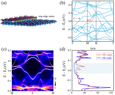
We note that in experiments, edge states [Fig. 4(a)] are observed when the bias voltage is within the gap range of the CDW structures Yin et al. (2022), indicating the topological nature of the antiferromagnetic CDW phase. To shed light on these observations, we calculate the band structures and edge states of the single kagome layer for the 22 structure. The band structures of the monolayer are shown in Fig. 4(b). We find that there exists both Weyl points (protected by symmetry) and topologically nontrival Chern band near the Fermi level, which may lead to nontrivial edge states. As we can see from Fig. 4(c) that there exists prominent edge states for the single kagome layer. We further calculate both the edge and bulk density of states (DOS) for the case of single kagome layer in Fig. 4(d). A gap feature can be clearly seen in the bulk DOS, while large edge states appear within the bulk (partial) gap, consistent with the experiments Yin et al. (2022). More details for the single kagome-layer calculations can be found in Fig. S8 of SI sup . Moreover, we note that the Chern band of single-layer FeGe has a small bandwidth (eV) with van Hove singularities near the point near Fermi level [see Fig. 4(b)], which is expected to be unstable against electron-electron interactions, and may lead to novel correlated and topological states of matter such as topological density-wave states Polshyn et al. (2022); Pierce et al. (2021) and chiral superconductivity Qi et al. (2010).
To conclude, based on first principles calculations, we have systematically studied the electronic structures, Fermi-surface quantum fluctuations, as well as phonon properties of the antiferromagnetic kagome metal FeGe. We find that charge density wave emerges due to a subtle cooperation between - interactions and electron-phonon couplings, which leads to an unusual scenario of interaction-triggered phonon instabilities, and eventually yields a charge density wave (CDW) state. We further show that, in the CDW phase of such antiferromagnetic kagome metal, the ground-state current density distribution exhibits an intriguing star-of-David pattern, leading to flux density modulation, which can be potentially measured by neutron diffraction measurements. Such current loop pattern emerges as a result of the subtle interplay between magnetism, lattice geometry, charge order, and SOC, which can be described by a simple, yet universal, tight-binding theory including a Kane-Mele type SOC term and a magnetic exchange interaction. The monolayer form of FeGe in the CDW phase turns out to be a topological metal hosting both symmetry-protected Weyl points and flat Chern bands, which exhibits multiple low-energy edge states, which naturally explains the origin of the recently observed spin polarized step-edge states in FeGe. The flat Chern bands in monolayer FeGe may lead to novel topological and correlated quantum states under proper fillings, which may stimulate further experimental and theoretical studies. Our work sheds light on the intriguing magnetic and charge properties in kagome magnets, and will provide useful guidelines for future works.
Acknowledgements.
We thank Quansheng Wu and Xiangang Wan for valuable discussions. This work is supported by the National Natural Science Foundation of China (grant No. 12174257), the National Key R & D program of China (grant No. 2020YFA0309601), and the start-up grant of ShanghaiTech University. Supplementary Information for “Theory for charge density wave and orbital-flux state in antiferromagnetic kagome metal FeGe”I I. First principles methods
I.1 Details for the first-principles calculations
The first-principles calculations are performed with the Vienna ab initio simulation package (VASP) which adopts the projector-augmented wave method Kresse and Furthmüller (1996). The energy cutoff is set at 465 eV for FeGe and 402 eV for Co3Sn2S2, Fe3Sn and FeSn. Exchange-correlation functional of the Perdew-Burke-Ernzerhof (PBE) type is used for both the structural relaxations and electronic structures calculations Perdew et al. (1996). The convergence criteria for the total energy is set to 10-6 eV. The BZ is sampled by a 10106, 10104, 121216. 101012 mesh for the pristine structure of FeGe, Co3Sn2S2, Fe3Sn and FeSn , respectively. For the 22 and 12 supercell structure of FeGe, a 665 and a 1066 k-meshs are adopted with the -centered scheme. Rotationally invariant “DFT+” scheme Liechtenstein et al. (1995) is adopted for some of the calculations, where the Hubbard on-site is determined through the linear-response method Cococcioni and de Gironcoli (2005) for FeGe (with eV). The Hund’s rule coupling is set to . We have also calculated the current loop patterns for other magnetic metals including Fe3Sn ( eV) and Co3Sn2S2 (with eV), see Sec. IV.1.
I.2 Inter-site currents
Inter-site current patterns are calculated based on the Wannier tight-binding models which are obtained through the VASP2WANNIER90 interface Mostofi et al. (2008). Here we give the details of the fomalism. The rate of change of charge density at an atomic site is expressed as
| (2) |
where {, } refers to the orbital indices and {, } refers to the site (or sublattice) indices. is the electron number operator in the Wannier basis, and ( is the band index, is the step function) is the density operator in the Bloch basis. Here is expressed as , and . We define the inter-site current between site and as .
II II. Topological properties and electronic structures of pristine FeGe
II.1 Topological properties of pristine FeGe
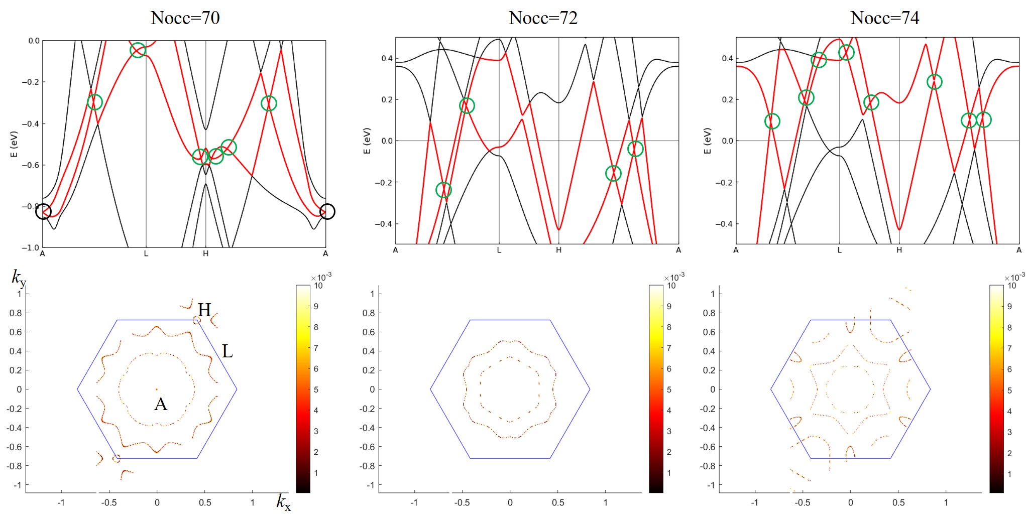
The band structures of the pristine FeGe are shown in Fig. 1(b) of main text. Due to the spatial inversion combined with time-reversal half lattice translation symmetry, the energy bands are all doubly degenerate though the system is antimagnetic. We focus on the three pairs of energy bands near the Fermi level, which are labelled band indices 70, 72 and 74. We then search the crossing points between each pairs of bands, which can be identified with the help of the direct gap (or topological gap) between 70-71, 72-73 bands and so on. We plot the results in Fig. 5, where the touching points of the bands along the high-symmetry path are marked with black or green circles. Our calculations show that there exists Dirac points and/or Dirac nodal loops over the plane for all the three cases, which are protected by spatial inversion combined with time-reversal half lattice translation symmetry and the mirror symmetry with respect to the kagome plane. Specifically, when the highest number of occupied band is set to 70 (i.e., Nocc=70), there is a Dirac point at the point. Additionally, there are two large nodal loops circling the point and one small triangular-like nodal loop circling the point. When Nocc=72, there are multiple Dirac points and only one nodal loop circling the point. When Nocc=74, there would be two nodal loops circling the point, one nodal loop circling the point and one nodal loop circling the point.
II.2 DFT+ band structures of pristine FeGe
In this subsection we show the DFT+ band structures of pristine FeGe with different values, as shown in Fig. 6
III III. Generalized susceptibility tensors
III.1 Formalism
We calculate the bare static generalized susceptibility tensor of pristine FeGe along a symmetry path within the first Brillouin zone, which is expressed as
| (3) |
where , are composite indices referring to the sublattice, orbital and spin degrees of freedom, and are the band indices, and is the volume of the unit cell. is the Fermi-Dirac distribution function at zero temperature, with denoting the band energy of the th band at wavevector , and is the corresponding eigenfunction in the basis of the Fourier-transformed Wannier functions. The calculations are start from the DFT-based Wannier tight-binding Hamiltonian Mostofi et al. (2008). A linear tetrahedra interpolation method is applied for the integration of the points over the first Brillouin zone Rath and Freeman (1975) and a 303018 mesh is used. The summation over the bands are restricted to the 10 bands nearest to the Fermi energy. For the RPA susceptibility tensor, we use the Kanamori interactions as
| (4) |
where and are the intra-orbital and inter-orbital direct Coulomb interactions. and denote the Hunds’ coupling and pair hoppings respectively, and is the density operator. We let and such that Eq. (4) has full rotational invariance Georges et al. (2013). We have considered effects of density-density interactions between neighboring Fe and Ge sites,
| (5) |
with the interaction amplitude . The effects of Coulomb interactions on the generalized susceptibility tensor are treated within random phase approximation (RPA), including effects of both direct and exchange interactions as described by the bubble-like and ladder-like Feynmann diagrams for the two-particle correlation function. All these Coulomb interaction terms (after Fourier transform) can be expressed in matrix form denoted by , then the RPA generalized susceptibility tensor is expressed as
| (6) |
where and refer to the RPA and bare susceptibility tensor (at wavevector ) respectively. The “” in Eq. (6) denotes a matrix product operation.
III.2 More results
IV IV. General tight-binding theory
We start our discussion from the following simple tight-binding Hamiltonian for a monolayer ferromagnetic kagome lattice:
| (7) |
where refers to the nearest neighbor hopping, is the electron creation (annihilation) operator at site , is the spin index. The first term is the usual first-neighbor hopping within the kagome triangles. The second term is the Kane-Mele type SOC term Kane and Mele (2005) which is the generated by the internal in-plane electric field normal to the bond vector connecting the two sites and [see Fig. 8(a)]. The third term is the effective magnetic exchange interactions. In general, more terms can be included into the model to be more realistic. Such as next-nearest-neighbor hoppings and SOC can be added to the describe the DT current pattern, and an effective charge order can also be added to simulate the SoD current patterns.
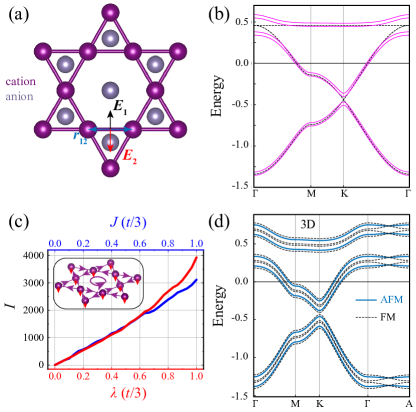
Generally, for the magnetic kagome compounds, the magnetic cations would form a kagome lattice, while the anions are typically located at the center of the hexagon and/or right on top of or at the bottom of the center of the triangles (see Fig. 8(a)). The experienced by the electrons hopping between nearby transition-metal cations thus is perpendicular to the bond vector . Typically there are two types of cations in the three dimensional (3D) kagome systems, one type of the cations are located at the center of the hexagons generating in-plane electric fields pointing towards hexagon center (denoted by in Fig. 8(a)), while the other ones are right on top of (or below) the triangle centers generating electric fields with the in-plane component pointing to the center of the triangles (denoted by ). and would compete with each other, which determines the sign of the current loops thus the direction of orbital magnetization in kagome magnetic metals. The third term in Eq. (7) is the antiferromagnetic exchange coupling term with denoting the coupling strength, and is the unit vector denoting the expectation value of the local magnetic moment at site which is FM within the kagome plane, and is coupled to the spin operator of itinerant electrons . Without SOC and the exchange coupling, the non-interacting band structures of the consist of a spin degenerate Dirac cone and a flat band as shown by the black lines in Fig. 8(b). Including SOC and the exchange coupling term would gap out the Dirac point and lift the spin degeneracy as shown by the red lines in Fig. 8(b).
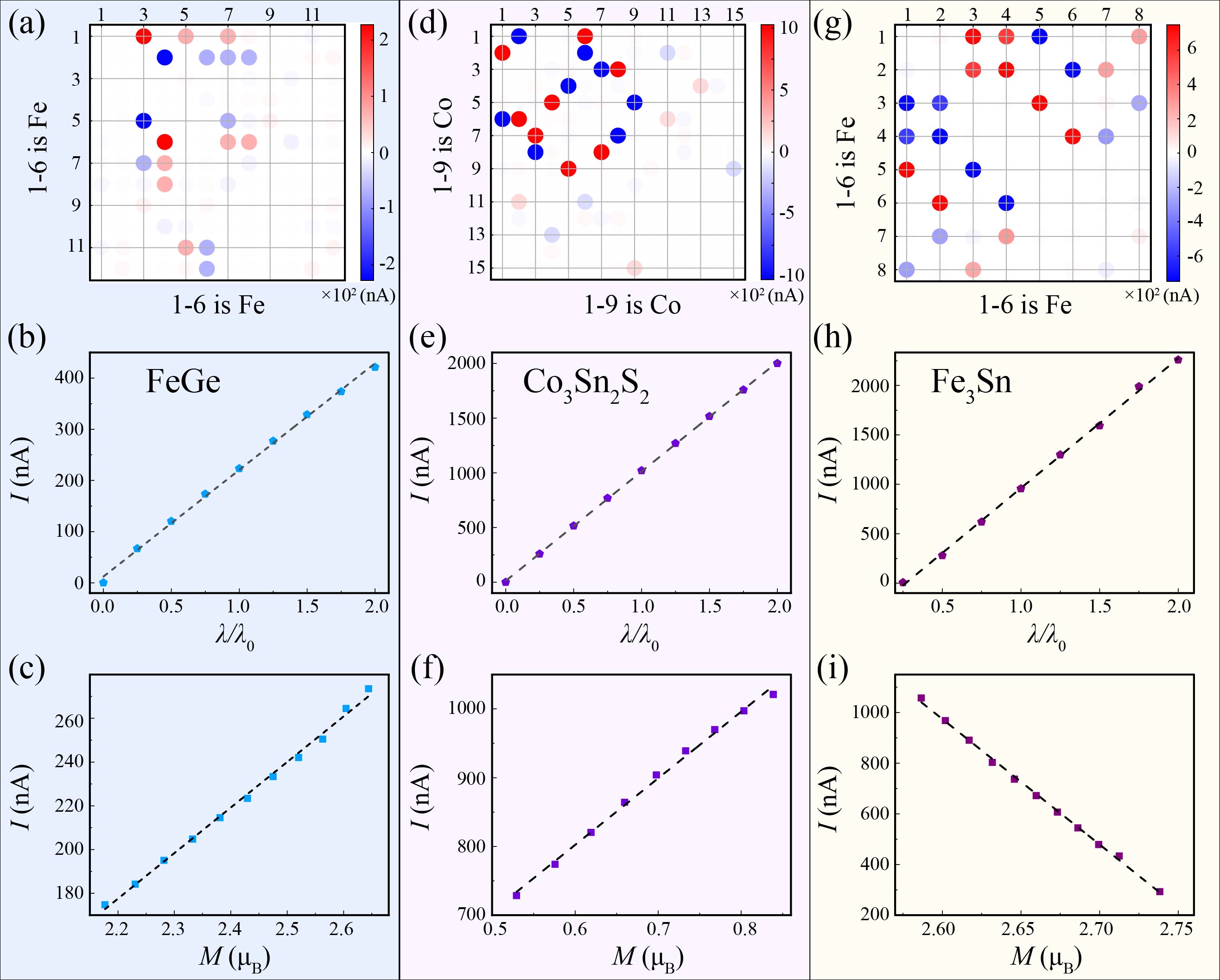
Circulating current loops within the kagome plane can be generated due to the interplay between ferromagnetism and SOC. Setting , , considering an out-of-plane magnetization pointing to negative direction () with , at half filling of the model, the calculated currents turn out to flow anticlockwise along the triangles, as shown in the inset of Fig. 8(c). Moreover, treating the SOC () and the exchange coupling () as a perturbation, the current amplitude turns out to be linearly dependent on both and as shown in Fig. 8(c). The ferromagnetic kagome monolayer (described by the Hamiltonian of Eq. (7)) can be stacked along the direction including the inter-layer coupling (with amplitude ), which would yield a Hamiltonian describing the electronic structure of a 3D kagome magnet. In Fig. 8(d) we present the band structures of 3D kagome magnetic metals (with ), where the dash and solid lines denote the interlayer ferromagnetic and AFM configurations, respectively. Such a model Hamiltonian and its variant can be applied to various ferromagnetic and antiferromagnetic 3D kagome magnetic metals such as FeGe, Co3Sn2S2, Fe3Sn, which are typical kagome compounds with collinear magnetic order.
IV.1 Current patterns in some other kagome magnetic metals
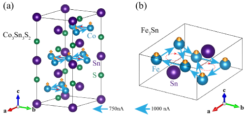
We also consider Co3Sn2S2, which is a half-metallic ferromagnet. The Curie temperature of Co3Sn2S2 is 177 K with the saturated magnetization 0.29 per Co atom Yin et al. (2019). Its space group is (No. 166) with hexagonal lattice constant Å, ÅYin et al. (2019). The kagome plane consists of the Co3Sn layer with the Sn atom located at the center of the hexagon, while the S atoms are stacked on top of (and below) the center of the Co triangles [see Fig. 9(a)]. A hexagonal Sn layer is further intercalated between two adjacent Co3Sn layers. The system exhibits giant anomalous Hall effect (AHE) which is believed to be contributed from the Weyl fermions near the Fermi energy Liu et al. (2018b); Wang et al. (2018). Other than the AHE, STM experiments had observed negative flat-band orbital magnetism Yin et al. (2019).
In order to understand the negative orbital magnetism Yin et al. (2019), we calculate the inter-site current patterns as shown in Fig. 9(a) and Fig. 10. As expected, the calculated inter-site currents flow along a loop within each ferromagnetic kagome layer generating an orbital flux through the kagome plane, which can be qualitatively described by the current pattern in Fig. 8(c). The dramatic difference of electric negativities between the Co cation and the S anion would give rise to a strong in-plane electric field and a large Kane-Mele type SOC amplitude . Because the inter-site current amplitude is linearly dependent on and (Fig. 10), the large Kane-Mele SOC generates an inter-site current as large as 1000 nA and an orbital magnetization on the order of per cell that is anti-parallel to the spin magnetization. This explains the origin of the giant negative orbital magnetism observed in experiments Yin et al. (2019).
Our theory can also be applied to Fe3Sn, whose primitive cell consists of two Fe3Sn kagome layers with short interlayer distance (thus strong interlayer couplings), with an hexagonal lattice constants Å and Å, as shown in Fig. 4b. The system is ferromagnetic with a Curie temperature K Trumpy et al. (1970). By virtue of the strong short interlayer distance and strong interlayer coupling, the calculated current pattern in Fig. 9b involves both intra-layer and interlayer current loops with the current amplitude as large as nA, forming a intercalated network flowing through the 3D kagome lattice. Moreover, different from Co3Sn2S2, in which the orbital magnetization generated by the circulating current is anti-parallel to the spin magnetization, here they are parallel to each other in Fe3Sn (Fig. 10).
IV.2 Tight-binding model for supercell structure
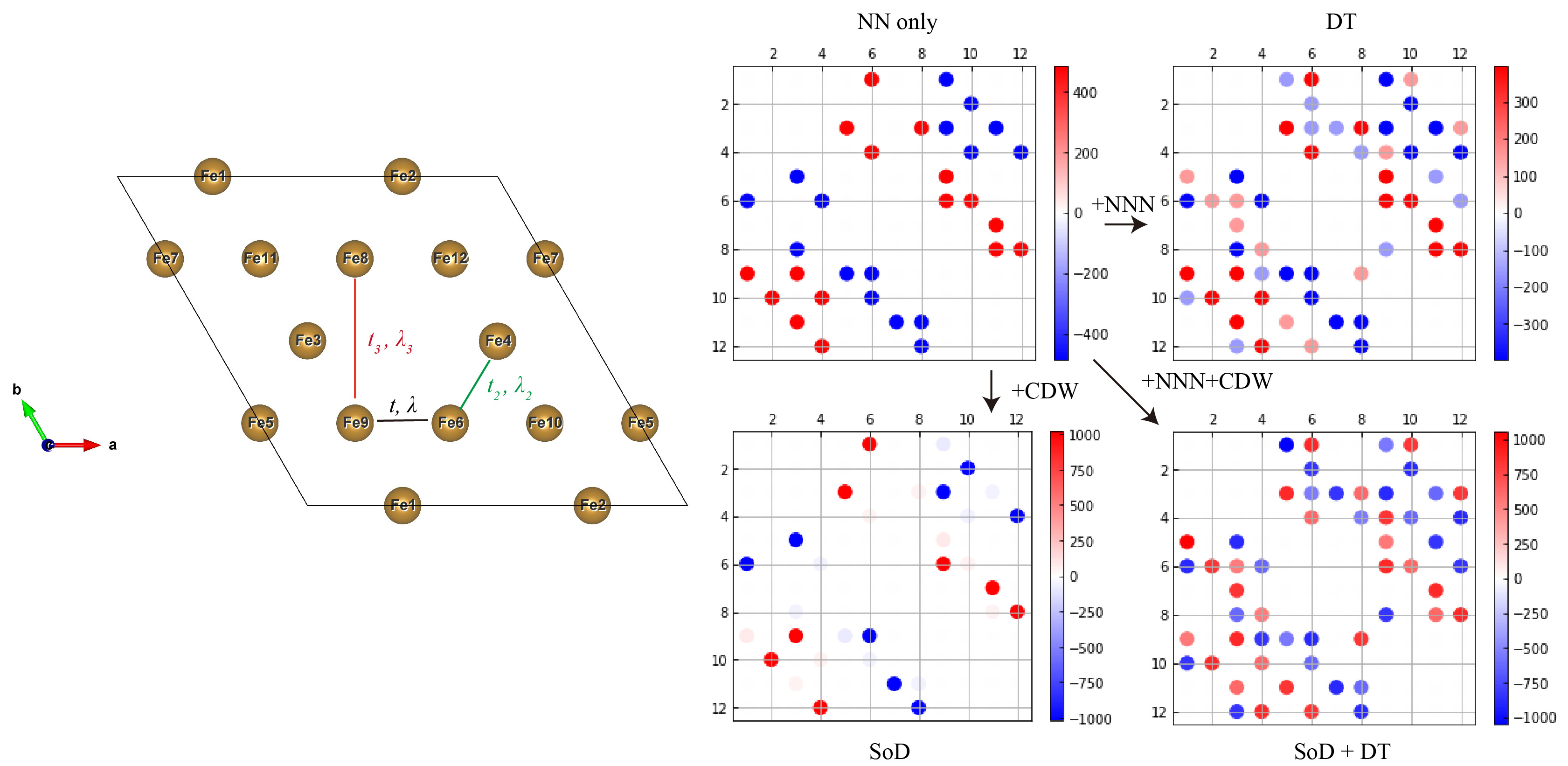
In the main text, we mentioned that more terms can be added to Eq. (7) to describe a more realistic structure such as the CDW phase of FeGe. Here we make some extensions on Eq. (7). Start from the supercell structure with only the nearest-neighbor (NN) interactions, we fisrt added the next-nearest-neighbor (NNN) hoppings and SOC. Usually, the NNN interactions are small compared with the NN interactions and in generally play a negligible role in the current patterns. However, in some case such as the CDW phase of FeGe, the two become comparable, then the DT current patterns induced by the NNN interactions would also become important. Inclucing the NNN interactions to Eq. (7) is direct, and the resulted current pattern is shown in Fig. 11 We then consider the CDW order, which can be included to Eq. (7) phenomenally as distortions to the NN and NNN interactions. Here we only consider its effects on the NN interactions, which modify some to . Without NNN interactions, the resulted SoD current pattern can be clearly found in Fig. 11when is a little bit smaller than . Finally, we incorporate all the ingradients into together, the resulted current patterns contained both DT and SoD patterns, which can well reproduced the results in CDW phase of FeGe. By now, the simple extension to the tight-binding model done well, more delicate modifications to Eq. (7) should be made when trying to apply to more realistic cases.
References
- Bergman et al. (2008) D. L. Bergman, C. Wu, and L. Balents, Phys. Rev. B 78, 125104 (2008).
- Zhou et al. (2017) Y. Zhou, K. Kanoda, and T.-K. Ng, Reviews of Modern Physics 89, 025003 (2017), ISSN 0034-6861.
- Neupert et al. (2022) T. Neupert, M. M. Denner, J.-X. Yin, R. Thomale, and M. Z. Hasan, Nature Physics 18, 137 (2022), ISSN 1745-2473.
- Yin et al. (2022) J.-X. Yin, B. Lian, and M. Z. Hasan, Nature 612, 647 (2022), ISSN 1476-4687.
- Tang et al. (2011) E. Tang, J.-W. Mei, and X.-G. Wen, Phys. Rev. Lett. 106, 236802 (2011).
- Kiesel et al. (2013a) M. L. Kiesel, C. Platt, and R. Thomale, Phys. Rev. Lett. 110, 126405 (2013a).
- Wang et al. (2013) W.-S. Wang, Z.-Z. Li, Y.-Y. Xiang, and Q.-H. Wang, Phys. Rev. B 87, 115135 (2013).
- Kiesel and Thomale (2012) M. L. Kiesel and R. Thomale, Phys. Rev. B 86, 121105 (2012).
- Yu and Li (2012) S.-L. Yu and J.-X. Li, Phys. Rev. B 85, 144402 (2012).
- Yin et al. (2018a) J.-X. Yin, S. S. Zhang, H. Li, K. Jiang, G. Chang, B. Zhang, B. Lian, C. Xiang, I. Belopolski, H. Zheng, et al., Nature 562, 91 (2018a).
- Ye et al. (2018a) L. Ye, M. Kang, J. Liu, F. Von Cube, C. R. Wicker, T. Suzuki, C. Jozwiak, A. Bostwick, E. Rotenberg, D. C. Bell, et al., Nature 555, 638 (2018a).
- Liu et al. (2018a) E. Liu, Y. Sun, N. Kumar, L. Muechler, A. Sun, L. Jiao, S.-Y. Yang, D. Liu, A. Liang, Q. Xu, et al., Nature physics 14, 1125 (2018a).
- Yin et al. (2020) J.-X. Yin, W. Ma, T. A. Cochran, X. Xu, S. S. Zhang, H.-J. Tien, N. Shumiya, G. Cheng, K. Jiang, B. Lian, et al., Nature 583, 533 (2020).
- Ko et al. (2009) W.-H. Ko, P. A. Lee, and X.-G. Wen, Physical Review B 79, 214502 (2009).
- Balents (2010) L. Balents, Nature 464, 199 (2010).
- Kiesel et al. (2013b) M. L. Kiesel, C. Platt, and R. Thomale, Physical review letters 110, 126405 (2013b).
- Yin et al. (2018b) J.-X. Yin, S. S. Zhang, H. Li, K. Jiang, G. Chang, B. Zhang, B. Lian, C. Xiang, I. Belopolski, H. Zheng, et al., Nature 562, 91 (2018b), ISSN 0028-0836.
- Ye et al. (2018b) L. Ye, M. Kang, J. Liu, F. von Cube, C. R. Wicker, T. Suzuki, C. Jozwiak, A. Bostwick, E. Rotenberg, D. C. Bell, et al., Nature 555, 638 (2018b), ISSN 0028-0836.
- Xu et al. (2015) G. Xu, B. Lian, and S.-C. Zhang, Physical Review Letters 115, 186802 (2015), ISSN 0031-9007, URL https://link.aps.org/doi/10.1103/PhysRevLett.115.186802.
- Wu et al. (2021a) X. Wu, T. Schwemmer, T. Müller, A. Consiglio, G. Sangiovanni, D. Di Sante, Y. Iqbal, W. Hanke, A. P. Schnyder, M. M. Denner, et al., Physical review letters 127, 177001 (2021a).
- Feng et al. (2021) X. Feng, K. Jiang, Z. Wang, and J. Hu, Science Bulletin (2021).
- Gu et al. (2021) Y. Gu, Y. Zhang, X. Feng, K. Jiang, and J. Hu, arXiv preprint arXiv:2108.04703 (2021).
- Park et al. (2021) T. Park, M. Ye, and L. Balents, Phys. Rev. B 104, 035142 (2021).
- Ortiz et al. (2020) B. R. Ortiz, S. M. Teicher, Y. Hu, J. L. Zuo, P. M. Sarte, E. C. Schueller, A. M. Abeykoon, M. J. Krogstad, S. Rosenkranz, R. Osborn, et al., Physical Review Letters 125, 247002 (2020), ISSN 0031-9007.
- Jiang et al. (2021a) Y.-X. Jiang, J.-X. Yin, M. M. Denner, N. Shumiya, B. R. Ortiz, G. Xu, Z. Guguchia, J. He, M. S. Hossain, X. Liu, et al., Nature Materials 20, 1353 (2021a), ISSN 1476-1122.
- Zhao et al. (2021) H. Zhao, H. Li, B. R. Ortiz, S. M. L. Teicher, T. Park, M. Ye, Z. Wang, L. Balents, S. D. Wilson, and I. Zeljkovic, Nature 599, 216 (2021), ISSN 0028-0836.
- Ortiz et al. (2021a) B. R. Ortiz, P. M. Sarte, E. M. Kenney, M. J. Graf, S. M. L. Teicher, R. Seshadri, and S. D. Wilson, Physical Review Materials 5, 034801 (2021a), ISSN 2475-9953.
- Chen et al. (2021a) K. Chen, N. Wang, Q. Yin, Y. Gu, K. Jiang, Z. Tu, C. Gong, Y. Uwatoko, J. Sun, H. Lei, et al., Physical Review Letters 126, 247001 (2021a), ISSN 0031-9007.
- Chen et al. (2021b) H. Chen, H. Yang, B. Hu, Z. Zhao, J. Yuan, Y. Xing, G. Qian, Z. Huang, G. Li, Y. Ye, et al., Nature 599, 222 (2021b), ISSN 0028-0836.
- Yu et al. (2021a) F. H. Yu, D. H. Ma, W. Z. Zhuo, S. Q. Liu, X. K. Wen, B. Lei, J. J. Ying, and X. H. Chen, Nature Communications 12, 3645 (2021a), ISSN 2041-1723.
- Xu et al. (2021) H.-S. Xu, Y.-J. Yan, R. Yin, W. Xia, S. Fang, Z. Chen, Y. Li, W. Yang, Y. Guo, and D.-L. Feng, Physical Review Letters 127, 187004 (2021), ISSN 0031-9007.
- Yin et al. (2021) L. Yin, D. Zhang, C. Chen, G. Ye, F. Yu, B. R. Ortiz, S. Luo, W. Duan, H. Su, J. Ying, et al., Physical Review B 104, 174507 (2021), ISSN 2469-9950.
- Li et al. (2021) H. Li, T. Zhang, T. Yilmaz, Y. Pai, C. Marvinney, A. Said, Q. Yin, C. Gong, Z. Tu, E. Vescovo, et al., Physical Review X 11, 031050 (2021), ISSN 2160-3308.
- Zhang et al. (2021) Z. Zhang, Z. Chen, Y. Zhou, Y. Yuan, S. Wang, J. Wang, H. Yang, C. An, L. Zhang, X. Zhu, et al., Physical Review B 103, 224513 (2021), ISSN 2469-9950.
- Ortiz et al. (2021b) B. R. Ortiz, S. M. Teicher, L. Kautzsch, P. M. Sarte, N. Ratcliff, J. Harter, J. P. Ruff, R. Seshadri, and S. D. Wilson, Physical Review X 11, 041030 (2021b), ISSN 2160-3308.
- Wu et al. (2021b) Q. Wu, Z. X. Wang, Q. M. Liu, R. S. Li, S. X. Xu, Q. W. Yin, C. S. Gong, Z. J. Tu, H. C. Lei, T. Dong, et al. (2021b).
- Kang et al. (2021) M. Kang, S. Fang, J.-K. Kim, B. R. Ortiz, S. H. Ryu, J. Kim, J. Yoo, G. Sangiovanni, D. D. Sante, B.-G. Park, et al. (2021).
- Yu et al. (2021b) L. Yu, C. Wang, Y. Zhang, M. Sander, S. Ni, Z. Lu, S. Ma, Z. Wang, Z. Zhao, H. Chen, et al., arXiv preprint arXiv:2107.10714 (2021b).
- Nakayama et al. (2021) K. Nakayama, Y. Li, T. Kato, M. Liu, Z. Wang, T. Takahashi, Y. Yao, and T. Sato, Physical Review B 104, L161112 (2021), ISSN 2469-9950.
- Li et al. (2022a) H. Li, S. Wan, H. Li, Q. Li, Q. Gu, H. Yang, Y. Li, Z. Wang, Y. Yao, and H.-H. Wen, Physical Review B 105, 045102 (2022a), ISSN 2469-9950.
- Liu et al. (2021) Z. Liu, N. Zhao, Q. Yin, C. Gong, Z. Tu, M. Li, W. Song, Z. Liu, D. Shen, Y. Huang, et al., Physical Review X 11, 041010 (2021), ISSN 2160-3308.
- Cho et al. (2021) S. Cho, H. Ma, W. Xia, Y. Yang, Z. Liu, Z. Huang, Z. Jiang, X. Lu, J. Liu, Z. Liu, et al., Physical Review Letters 127, 236401 (2021), ISSN 0031-9007.
- Zhou et al. (2021) X. Zhou, Y. Li, X. Fan, J. Hao, Y. Dai, Z. Wang, Y. Yao, and H.-H. Wen, Physical Review B 104, L041101 (2021), ISSN 2469-9950.
- Xie et al. (2022) Y. Xie, Y. Li, P. Bourges, A. Ivanov, Z. Ye, J.-X. Yin, M. Z. Hasan, A. Luo, Y. Yao, Z. Wang, et al., Physical Review B 105, L140501 (2022), ISSN 2469-9950.
- Wulferding et al. (2021) D. Wulferding, S. Lee, Y. Choi, Q. Yin, Z. Tu, C. Gong, H. Lei, and K.-Y. Choi (2021).
- Wang et al. (2021) Z. X. Wang, Q. Wu, Q. W. Yin, C. S. Gong, Z. J. Tu, T. Lin, Q. M. Liu, L. Y. Shi, S. J. Zhang, D. Wu, et al., Physical Review B 104, 165110 (2021), ISSN 2469-9950.
- Song et al. (2021) B. Q. Song, X. M. Kong, W. Xia, Q. W. Yin, C. P. Tu, C. C. Zhao, D. Z. Dai, K. Meng, Z. C. Tao, Z. J. Tu, et al. (2021).
- Nie et al. (2022) L. Nie, K. Sun, W. Ma, D. Song, L. Zheng, Z. Liang, P. Wu, F. Yu, J. Li, M. Shan, et al., Nature 604, 59 (2022), ISSN 0028-0836.
- Mielke et al. (2022) C. Mielke, D. Das, J.-X. Yin, H. Liu, R. Gupta, Y.-X. Jiang, M. Medarde, X. Wu, H. C. Lei, J. Chang, et al., Nature 602, 245 (2022), ISSN 1476-4687.
- Lou et al. (2022) R. Lou, A. Fedorov, Q. Yin, A. Kuibarov, Z. Tu, C. Gong, E. F. Schwier, B. Büchner, H. Lei, and S. Borisenko, Physical Review Letters 128, 036402 (2022), ISSN 0031-9007.
- Li et al. (2022b) H. Li, H. Zhao, B. R. Ortiz, T. Park, M. Ye, L. Balents, Z. Wang, S. D. Wilson, and I. Zeljkovic, Nature Physics 18, 265 (2022b), ISSN 1745-2473.
- Wu et al. (2022) S. Wu, B. R. Ortiz, H. Tan, S. D. Wilson, B. Yan, T. Birol, and G. Blumberg, Physical Review B 105, 155106 (2022), ISSN 2469-9950.
- Shan et al. (2022) Z. Shan, P. K. Biswas, S. K. Ghosh, T. Tula, A. D. Hillier, D. Adroja, S. Cottrell, G.-H. Cao, Y. Liu, X. Xu, et al., Phys. Rev. Research 4, 033145 (2022).
- Jiang et al. (2021b) Y.-X. Jiang, J.-X. Yin, M. M. Denner, N. Shumiya, B. R. Ortiz, G. Xu, Z. Guguchia, J. He, M. S. Hossain, X. Liu, et al., Nature Materials pp. 1–5 (2021b).
- Varma (1997) C. M. Varma, Phys. Rev. B 55, 14554 (1997).
- Liu et al. (2016) J. Liu, S. Y. Park, K. F. Garrity, and D. Vanderbilt, Phys. Rev. Lett. 117, 257201 (2016), URL https://link.aps.org/doi/10.1103/PhysRevLett.117.257201.
- Liu and Dai (2021) J. Liu and X. Dai, Nature Reviews Physics 3, 367 (2021).
- Bourges et al. (2021) P. Bourges, D. Bounoua, and Y. Sidis, Comptes Rendus. Physique 22, 7 (2021).
- Denner et al. (2021) M. M. Denner, R. Thomale, and T. Neupert, Phys. Rev. Lett. 127, 217601 (2021).
- Ma and Liu (2021) H.-Y. Ma and J. Liu, arXiv preprint arXiv:2112.02808 (2021).
- Yin et al. (2022) J.-X. Yin, Y.-X. Jiang, X. Teng, M. Shafayat Hossain, S. Mardanya, T.-R. Chang, Z. Ye, G. Xu, M. M. Denner, T. Neupert, et al., arXiv e-prints arXiv:2203.01888 (2022), eprint 2203.01888.
- Teng et al. (2022a) X. Teng, L. Chen, F. Ye, E. Rosenberg, Z. Liu, J.-X. Yin, Y.-X. Jiang, J. S. Oh, M. Z. Hasan, K. J. Neubauer, et al., Nature (2022a).
- Teng et al. (2022b) X. Teng, J. S. Oh, H. Tan, L. Chen, J. Huang, B. Gao, J.-X. Yin, J.-H. Chu, M. Hashimoto, D. Lu, et al., arXiv preprint arXiv:2210.06653 (2022b).
- Miao et al. (2022) H. Miao, T. T. Zhang, H. X. Li, G. Fabbris, A. H. Said, R. Tartaglia, T. Yilmaz, E. Vescovo, J. X. Yin, S. Murakami, et al., arXiv preprint arXiv:2210.06359 (2022).
- Shao et al. (2022) S. Shao, J.-X. Yin, I. Belopolski, J.-Y. You, T. Hou, H. Chen, Y.-X. Jiang, M. S. Hossain, M. Yahyavi, C.-H. Hsu, et al., arXiv preprint arXiv:2206.12033 (2022).
- Zhou et al. (2022) H. Zhou, S. Yan, D. Fan, D. Wang, and X. Wan, arXiv preprint arXiv:2211.15545 (2022).
- Wu et al. (2023) L. Wu, Y. Hu, D. Wang, and X. Wan, arXiv preprint arXiv:2302.03622 (2023).
- Bernhardt and LebechS (1984) J. Bernhardt and B. LebechS, J. Phys. F: Met. Phys 14, 2379 (1984).
- Liechtenstein et al. (1995) A. I. Liechtenstein, V. I. Anisimov, and J. Zaanen, Physical Review B 52, R5467 (1995), ISSN 0163-1829.
- Cococcioni and de Gironcoli (2005) M. Cococcioni and S. de Gironcoli, Physical Review B 71, 035105 (2005), ISSN 1098-0121.
- (71) See Supplementary Information for 1. Tight-binding theory and tight-binding models of the 22 structure. 2. Calculational method s. 3. Discussions of the topological properties. 4. Bare and RPA generalized susceptibility tensors of the pristine FeGe. 5. Additional figures.
- Giustino (2017) F. Giustino, Rev. Mod. Phys. 89, 015003 (2017).
- Liu and Balents (2017) J. Liu and L. Balents, Phys. Rev. B 95, 075426 (2017).
- Uehara et al. (2015) A. Uehara, H. Shinaoka, and Y. Motome, Phys. Rev. B 92, 195150 (2015).
- Qiu et al. (2021) W.-X. Qiu, J.-Y. Zou, A.-Y. Luo, Z.-H. Cui, Z.-D. Song, J.-H. Gao, Y.-L. Wang, and G. Xu, Phys. Rev. Lett. 127, 147202 (2021).
- Ma et al. (2022) H.-Y. Ma, J.-X. Yin, M. Zahid Hasan, and J. Liu, Phys. Rev. B 106, 155125 (2022).
- Teng et al. (2022c) X. Teng, L. Chen, F. Ye, E. Rosenberg, Z. Liu, J.-X. Yin, Y.-X. Jiang, J. S. Oh, M. Z. Hasan, K. J. Neubauer, et al., arXiv preprint arXiv:2203.11467 (2022c).
- Kane and Mele (2005) C. L. Kane and E. J. Mele, Physical Review Letters 95 (2005), ISSN 00319007.
- Polshyn et al. (2022) H. Polshyn, Y. Zhang, M. A. Kumar, T. Soejima, P. Ledwith, K. Watanabe, T. Taniguchi, A. Vishwanath, M. P. Zaletel, and A. F. Young, Nature Physics 18, 42 (2022), ISSN 1745-2481.
- Pierce et al. (2021) A. T. Pierce, Y. Xie, J. M. Park, E. Khalaf, S. H. Lee, Y. Cao, D. E. Parker, P. R. Forrester, S. Chen, K. Watanabe, et al., Nature Physics 17, 1210 (2021), ISSN 1745-2481.
- Qi et al. (2010) X.-L. Qi, T. L. Hughes, and S.-C. Zhang, Phys. Rev. B 82, 184516 (2010).
- Kresse and Furthmüller (1996) G. Kresse and J. Furthmüller, Physcial Review B 54, 11169 (1996).
- Perdew et al. (1996) J. P. Perdew, K. Burke, and M. Ernzerhof, Physcial Review Letters 77, 3865 (1996).
- Mostofi et al. (2008) A. A. Mostofi, J. R. Yates, Y.-S. Lee, I. Souza, D. Vanderbilt, and N. Marzari, Computer physics communications 178, 685 (2008).
- Rath and Freeman (1975) J. Rath and A. J. Freeman, Phys. Rev. B 11, 2109 (1975).
- Georges et al. (2013) A. Georges, L. d. Medici, and J. Mravlje, Annu. Rev. Condens. Matter Phys. 4, 137 (2013).
- Yin et al. (2019) J.-X. Yin, S. S. Zhang, G. Chang, Q. Wang, S. S. Tsirkin, Z. Guguchia, B. Lian, H. Zhou, K. Jiang, I. Belopolski, et al., Nature Physics 15, 443 (2019), ISSN 1745-2473.
- Liu et al. (2018b) E. Liu, Y. Sun, N. Kumar, L. Muechler, A. Sun, L. Jiao, S.-Y. Yang, D. Liu, A. Liang, Q. Xu, et al., Nature Physics 14, 1125 (2018b), ISSN 1745-2473.
- Wang et al. (2018) Q. Wang, Y. Xu, R. Lou, Z. Liu, M. Li, Y. Huang, D. Shen, H. Weng, S. Wang, and H. Lei, Nature Communications 9, 3681 (2018), ISSN 2041-1723.
- Trumpy et al. (1970) G. Trumpy, E. Both, C. Djéga-Mariadassou, and P. Lecocq, Phys. Rev. B 2, 3477 (1970), URL https://link.aps.org/doi/10.1103/PhysRevB.2.3477.