Flat-band localization and interaction-induced delocalization of photons
Abstract
Advances in quantum engineering have enabled the design, measurement, and precise control of synthetic condensed matter systems altman_quantum_2021 . The platform of superconducting circuits offers two particular capabilities carusotto_photonic_2020 ; leykam_artificial_2018 : flexible connectivity of circuit elements that enables a variety of lattice geometries, and circuit nonlinearity that provides access to strongly interacting physics. Separately, these features have allowed for the creation of curved-space lattices kollar_hyperbolic_2019 and the realization of strongly correlated phases roushan_spectroscopic_2017 ; ma_dissipatively_2019 ; saxberg_disorder-assisted_2022 and dynamics yan_strongly_2019 ; gong_quantum_2021 ; karamlou_quantum_2022 in one-dimensional chains and square lattices. Missing in this suite of simulations is the simultaneous integration of interacting particles into lattices with unique band dispersions, such as dispersionless flat bands. An ideal building block for flat-band physics is the Aharonov-Bohm cage vidal_aharonov-bohm_1998 : a single plaquette of a lattice whose band structure consists entirely of flat bands. Here, we experimentally construct an Aharonov-Bohm cage and observe the localization of a single photon, the hallmark of all-bands-flat physics. Upon placing an interaction-bound photon pair into the cage, we see a delocalized walk indicating an escape from Aharonov-Bohm caging vidal_interaction_2000 . We further find that a variation of caging persists for two particles initialized on opposite sites of the cage. These results mark the first experimental observation of a quantum walk that becomes delocalized due to interactions and establish superconducting circuits for studies of flat-band-lattice dynamics with strong interactions.
Flat electronic bands quench the kinetic energy of electrons and provide a lattice environment that is uniquely susceptible to interactions, disorder, and particle statistics. As a result, they can host a wide range of phenomena, from itinerant ferromagnetism in spinful systems lieb_two_1989 ; tasaki_nagaokas_1998 to the fractional quantum Hall effect von_klitzing_quantum_2017 , fractional Chern insulator states bergholtz_topological_2013 ; parameswaran_fractional_2013 ; spanton_observation_2018 , and strongly correlated phases observed in magic-angle twisted bilayer graphene cao_unconventional_2018 ; xie_fractional_2021 . The role of flat bands in high-temperature superconductivity peotta_superfluidity_2015 ; julku_quantum_2021 and quantum thermalization goda_inverse_2006 ; danieli_many-body_2020 ; kuno_multiple_2021 , as well as searches for novel flat-band materials regnault_catalogue_2022 , are also active areas of research.
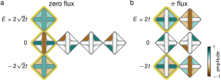
Many types of flat bands have been theoretically explored and classified, frequently within the tight-binding model of solids where flat bands can result from specific features in lattice geometry sutherland_localization_1986 . A simple example is the one-dimensional rhombus lattice, which contains three sites per unit cell and exhibits a flat middle band that touches dispersive bands above and below (see Fig. 1a). As with many flat bands, the eigenstates within the band can be written in a basis of real-space eigenfunctions known as compact localized states aoki_hofstadter_1996 . These states are characterized by a strict boundedness on the number of sites involved in the particle wavefunction, reflecting stronger localization than the more typical exponential localization of Wannier functions. At the same time, because dispersive bands are present in the band structure, an initially localized particle generically contains contributions from dispersive states and will delocalize across the lattice over time.
A type of extreme localization, in which every band of the spectrum is flat, emerges in select lattices and specific values of magnetic flux, including the rhombus lattice with flux. The effect of magnetic flux on localization depends heavily on lattice geometry and can be understood through the Aharonov-Bohm effect. More specifically, the tight-binding electron accumulates an Aharonov-Bohm phase as it hops around a closed loop of the lattice, or plaquette. Additionally, the lattice plaquettes are arranged in such a way that causes complete destructive wavefunction interference beyond some region of the lattice and localizes the electron to a finite number of sites. This phenomenon is known as Aharonov-Bohm “caging” vidal_aharonov-bohm_1998 . In the rhombus lattice, Aharonov-Bohm caging occurs at a magnetic field of half a flux quantum through each plaquette, corresponding to a geometric phase of . All three bands become flat and a complete basis of only compact localized states becomes possible (Fig. 1b). Accordingly, any initially localized particle will be in a superposition of a finite number of compact localized states and therefore will remain bounded in time.
Crucially, because of strict boundedness, the key physics of Aharonov-Bohm caging can be accessed through a single plaquette of the rhombus lattice with flux. In this four-site system, the eigenstates (Fig. 1d) exhibit similarities to the compact localized states of its lattice counterpart, despite having energies that differ from the continuum limit. In particular, none of these states extend across an entire plaquette, purely due to the same destructive wavefunction interference effects that give rise to Aharonov-Bohm caging in a lattice.
In this work, we leverage the flexible connectivity of superconducting circuits in a novel manner to realize one of these plaquettes, which we refer to as an Aharonov-Bohm cage. To allow geometric phase accumulation for microwave photons, which do not inherently respond to magnetic fields due to their neutral charge, we realize a -flux synthetic gauge field via a negative tunneling between two sites in the plaquette. We show how this negative tunneling allows us to turn on caging, by comparison to an analogous device without synthetic field. Next, we use on-site interactions between particles to demonstrate a bound particle pair escaping the cage. Finally, we find that unbound particle pairs remain caged in a multi-particle variation of Aharonov-Bohm caging.
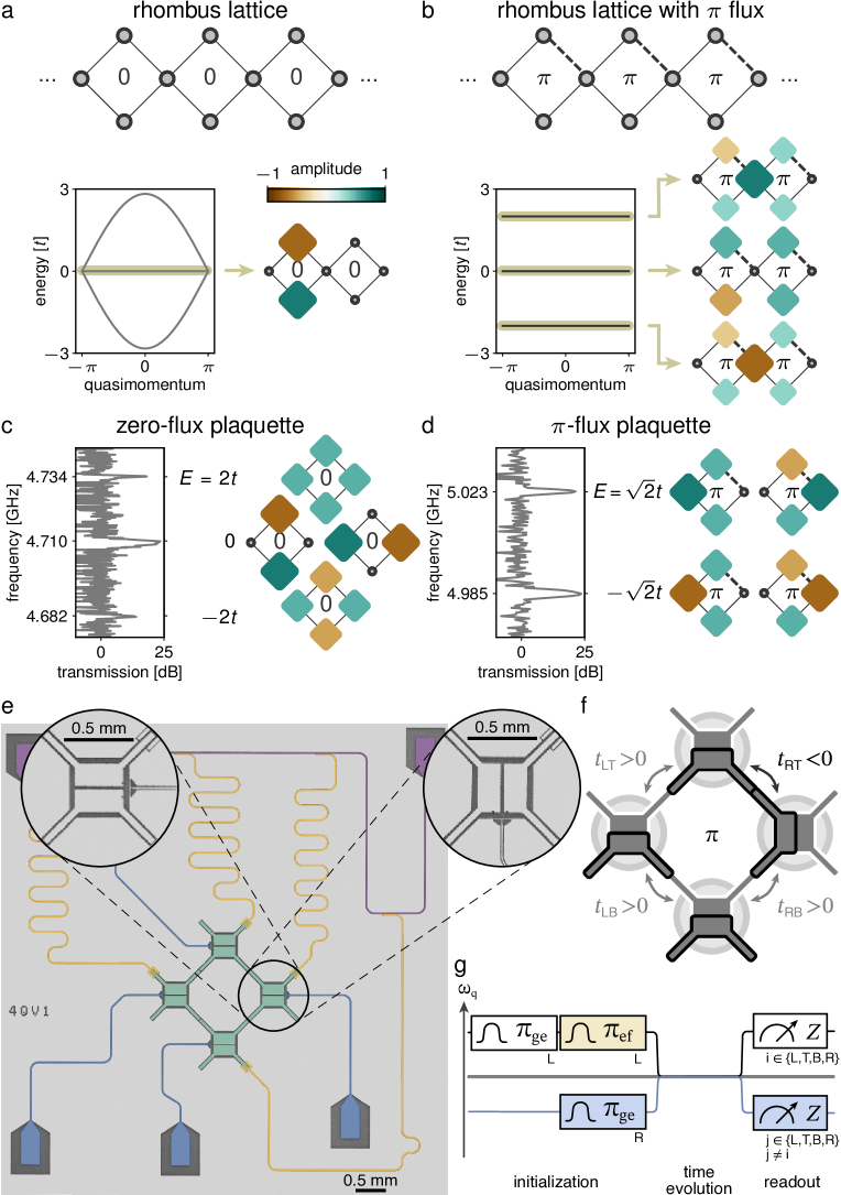
Circuit device
The sites of our plaquettes are flux-tunable transmon qubits which can be approximated as anharmonic oscillators for microwave photons. To implement the zero-flux rhombus plaquette, all four qubits are placed in the same orientation as shown in the main image of Fig. 1e. Each qubit has a large capacitor comprised of an upper and a lower electrode (shaded green), and tunnel coupling between neighboring qubits is given by capacitance between two of their electrodes. With upper electrodes capacitively coupled only to lower electrodes of neighboring qubits, the accumulated phase of a single photon traversing this loop is zero. To generate the -flux synthetic field, we rotate one transmon (the rightmost) clockwise by 90 degrees relative to the others. As shown in Fig. 1f, in doing so, the (formerly) lower electrode of the right qubit now couples to the lower electrode of the top qubit, while all other electrodes remain coupled as before. A single photon traversing this loop then picks up an additional minus sign when hopping between the top and right sites yanay_two-dimensional_2020 , i.e. a geometric phase of . We note that the choice of qubit to rotate and its rotation direction amount to a gauge choice, reflected in where the change in sign of tunneling occurs.
The resulting Hamiltonian for the two devices (in units where the reduced Planck constant ) is given by:
| (1) |
where the summations over sites and neighboring sites are taken over the left (L), top (T), bottom (B), and right (R) qubits. Here, is the bosonic annihilation operator and is the frequency of qubit . For the gauge choice in this work, the tunneling is positive between all qubits in the zero-flux rhombus. Rotation of the rightmost qubit for the -flux rhombus corresponds to changing the sign of tunneling between the right and top qubits () while preserving its magnitude. On-site attractive interactions are mediated by the negative qubit anharmonicity of transmon qubits. Both devices operate in the strongly interacting regime where the ratio of interaction strength to tunneling is approximately 13.5. Next-nearest neighbor coupling was designed to be negligible at less than and is not included in the model.
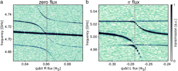
We probe each of the two devices via two-tone spectroscopy to confirm that their eigenenergies match the expected energies obtained by exact diagonalization of the corresponding four-site Hamiltonian. With all four qubits tuned into resonance with each other, we measure transmission through the feedline at the top-qubit resonator frequency while varying the frequency of the pump tone. Transmission peaks indicate that the resonator frequency has dispersively shifted, which occurs when the pump tone is resonant with a plaquette eigenenergy and excites the top qubit. The results are shown in Figs. 1c and d for the zero- and -flux rhombi, respectively, and are consistent with calculation. The measured spectral dependence on one of the qubit frequencies is included as Extended Data Fig. S1.
The experiments that follow probe non-equilibrium dynamics and consist of state initialization, time evolution, and readout (Fig. 1g). For Hamiltonian time evolution, we set the frequencies of all of the qubits to GHz. At this target frequency, the qubits have depolarization times exceeding 43 and nearest-neighbor tunneling amplitudes of approximately MHz. State initialization and readout are performed via a single feedline (shaded purple in Fig. 1e), with four half-wave resonators (shaded yellow) dispersively coupled to each qubit. In these steps, the frequency of each qubit can be dynamically set between and GHz by varying the current supplied to its individual flux bias line (shaded blue, Fig. 1e). A full table of device parameters can be found in Supplementary Information Tabs. S1 and S2.
Caging of a single particle
Aharonov-Bohm caging can be made apparent through a single-particle quantum walk abilio_magnetic_1999 ; naud_aharonovbohm_2002 ; mukherjee_experimental_2018 ; hung_quantum_2021 ; li_aharonov-bohm_2022 . Much like the walk in a one-dimensional chain karski_quantum_2009 ; preiss_strongly_2015 ; yan_strongly_2019 ; gong_quantum_2021 ; karamlou_quantum_2022 , the ensuing dynamics result from wavefunction interference. Here, destructive interference bounds the quantum walk in an Aharonov-Bohm cage, while constructive interference allows a fully delocalized walk over all four sites of the plaquette with zero flux.
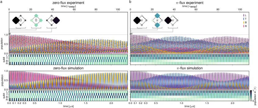
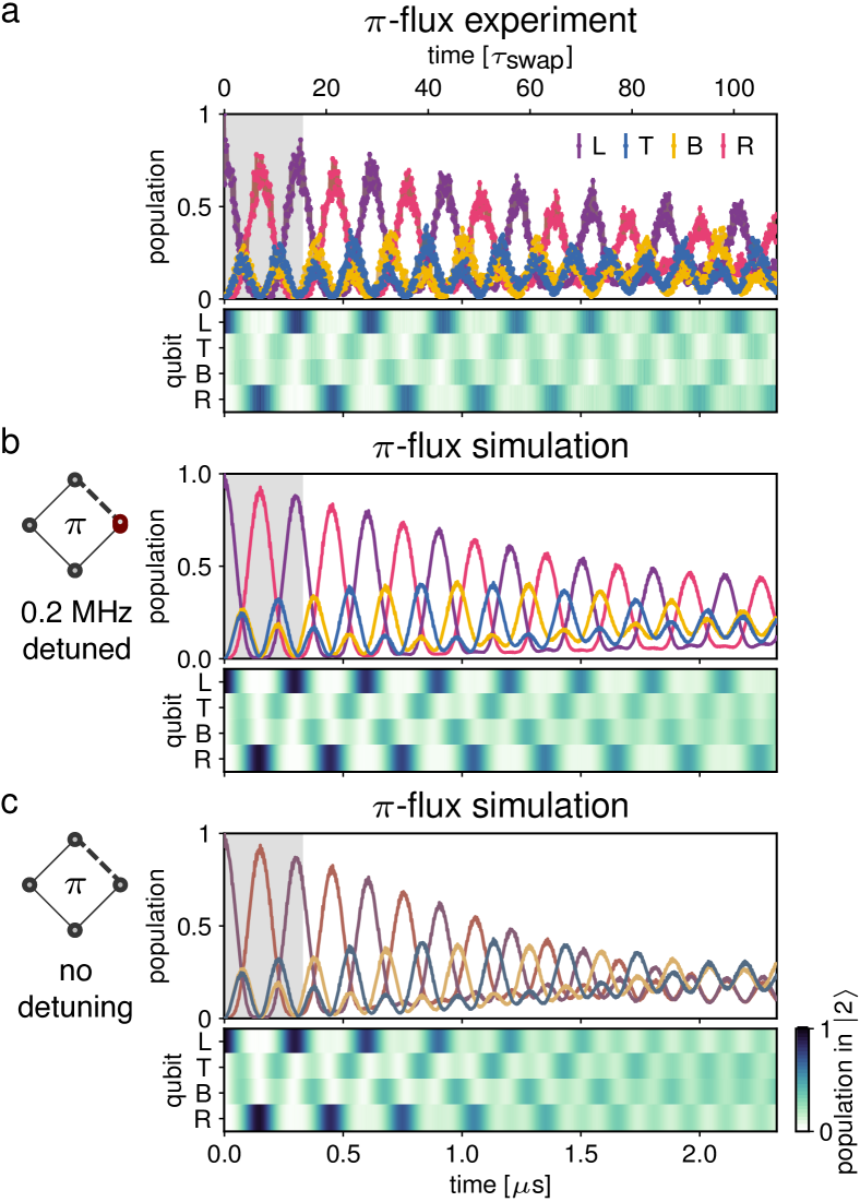
The experiment begins with initialization of the leftmost qubit, detuned from the target qubit frequency, in the first excited state (see Fig. 1d). This is equivalent to placing a single particle (microwave photon) on that site. We then quench the left qubit into resonance with the other three qubits at the target qubit frequency. After evolution under the Hamiltonian (Eq. 1) for a variable time, we diabatically detune and measure the state of one qubit. Repeated measurements across all qubits then provide access to the average site-resolved occupation of all four sites. The results for zero and flux, corrected for readout errors, are shown in Fig. 2a and b (upper), respectively. Duplicate time axes are included in units of : the time it takes for a photon to swap between two qubits with tunnelling rate , where MHz is the average rate for the zero-flux (-flux) device. Simulation results with zero on-site disorder and independently measured tunneling and decoherence are plotted below.
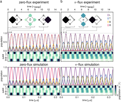
We find a bounded quantum walk in the -flux rhombus, indicating successful Aharonov-Bohm caging. Within the first swap time after quench, the particle begins to delocalize over the top and bottom sites in the plaquette regardless of flux. Shortly thereafter, however, the walks deviate. In the zero-flux rhombus, the top and bottom paths constructively interfere and result in a periodic walk across all four qubits, as demonstrated by the insets in Fig. 2a, upper. This does not occur for the -flux rhombus: interference is destructive on the rightmost site, suppressing particle population below 5% for over 9 swap times (Fig. 2b). Consequently, the particle remains bounded to the left, top, and bottom sites (insets in Fig. 2b, upper) as expected for caging.
The agreement between experimental measurement and simulation indicates that our control over qubit frequencies is consistent with achieving negligible on-site disorder and sufficient to realize caging. The slight deviation from ideal caging is instead limited predominantly due to disorder in the coupling strengths between qubits, which amounts to a spread of approximately 2.5% for the zero-flux device and 5.6% for the -flux device. This coupling-strength disorder results in coherent beating which is highlighted at long timescales (Extended Data Fig. S2).
Doublons escaping the cage
We next consider the walk of two particles initialized on the same site, referred to as a doublon. These doublon states span a subspace of the entire two-particle Hilbert space; the complement is spanned by two-particle states where the particles sit on different sites, which we will refer to as “particle-particle” Fock states. In the presence of strong interactions, the doublon states are energetically well-separated from the particle-particle states. In this subspace, doublons hop as a bound pair and experience a gauge field that is twice that of a single particle. The Aharonov-Bohm cage for a single particle, then, has no effect on a strongly interacting doublon.
We access the strongly interacting regime with our devices by designing interaction energies in excess of tunneling amplitudes by an order of magnitude. The doublon walk begins with two photons on the left site and continues with time evolution under the Hamiltonian as before, where on-site energies are now tuned to ensure that the second excited states of all qubits are on resonance. After a variable time, we measure the population of the second excited state and extract readout-error-corrected average doublon occupations of all sites.
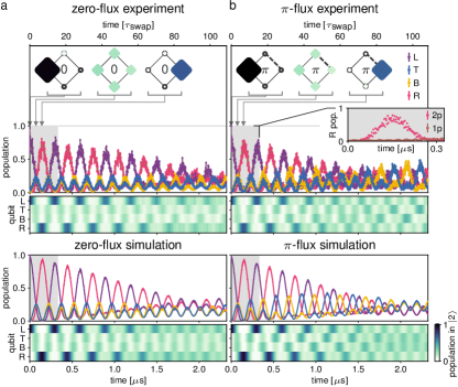
Doublons in the zero-flux rhombus delocalize in a manner qualitatively similar to single photons (Fig. 3a). Doublon dynamics in the -flux rhombus, however, markedly differ from single-photon caging in that the doublon does not remain bounded away from the rightmost site (Fig. 3b inset plot). Rather, the doublon fully explores the plaquette almost as if it were in the zero-flux plaquette, i.e. it escapes this Aharonov-Bohm cage.
We note that in both plaquettes, the doublon tunneling amplitude is reduced by almost an order of magnitude compared to the single-particle tunneling. These timescales result from doublons hopping via a second-order process, with rate given by for bare tunneling and negative anharmonicity . This effective tunneling provides another way of understanding the doublon escape: all four tunneling rates have the same sign regardless of the sign of , yielding zero flux. Additionally, the doublon-population oscillation amplitudes decrease over time, largely due to the weak hybridization between the doublon and particle-particle states, leading to coherent beating of the measured doublon population (see Supplementary Information for additional discussion).
Particle-Particle Fock-State Caging
Finally, we investigate the time dynamics of particle-particle Fock states and find a variation of Aharonov-Bohm caging. These states, where two particles sit on different sites and are not bound by interactions, comprise the second and remaining sector of two-particle states. In fact, strong interactions energetically separate these states from the doublons, making the individual particles behave approximately as hard-core bosons.
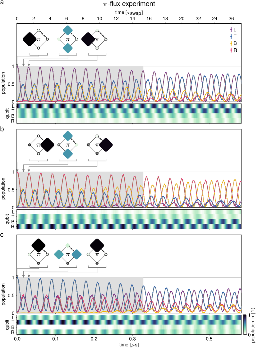
For these experiments, we initialize one photon on the left site and one photon on the right (the state). After time evolution, we perform simultaneous readout on all qubit pairs to extract average particle-particle Fock-state populations at various points in time and plot the results in Fig. 4a and b. The particle-particle dynamics in the zero-flux plaquette are dominated by full-contrast swaps between the and states. In contrast, we find a bounded walk in the -flux plaquette not in real space, but instead characterized by suppressed population transfer to the Fock state. We refer to this variation of caging as “Fock-state caging”.
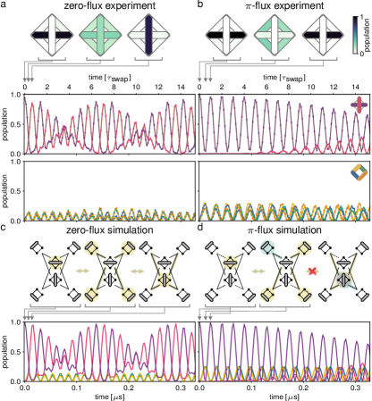
This bounded phenomenon is a direct consequence of Aharonov-Bohm caging extended to multi-particle sectors, seen through the corresponding Hamiltonian adjacency graphs in Figs. 4c and d. In these graphs, each node represents a particle-particle Fock state; doublon states are omitted in this hard-core limit. Two nodes are connected by edges if the Fock states are tunnel-coupled, and edges are weighted according to the coupling sign and magnitude. In this configuration space, time evolution of the state corresponds to a single-particle walk on the adjacency graph beginning on the node. Without a synthetic field, delocalization proceeds across the entire particle-particle subspace. Whereas, with flux, destructive interference much like in Aharonov-Bohm caging prohibits evolution to the state. In other words, Fock-state caging results from the interplay of geometric phase accumulation and Fock-state configurational-space topology, rather than real-space lattice topology as in Aharonov-Bohm caging. In multi-plaquette systems and the infinite lattice itself, this Fock-state caging may give rise to an interacting two-particle real-space caging effect santos_methods_2020 ; see Extended Data Fig. S4 for supporting evidence from simulations on a chain of three plaquettes.
The oscillating populations between the and states in the zero-flux rhombus display a beating effect. This coherent beating can be attributed to weak hybridization between the doublon and particle-particle states as in the doublon walk, reflecting a slight deviation of our device parameters from the hard-core regime (see Supplementary Information for details). Interestingly, the -flux rhombus does not host beating of these populations beyond what can be attributed to tunneling-rate disorder. The absence of beating suggests that the Fock-state caging effects are independent of interaction strength. In the regime of finite interactions, doublon states must be included in the adjacency graph; even so, we find that the resulting configuration-space topology maintains the complete destructive interference necessary for Fock-state caging.
Outlook
Our work experimentally demonstrates the Aharonov-Bohm caging of a single particle and the subsequent escape of deeply bound doublons from the cage. We realize this cage in a rhombus plaquette by engineering a negative tunnel coupling between exactly two of the transmon qubits to thread a -flux synthetic magnetic field through the plaquette. Additionally, we consider the correlated dynamics of two photons initialized on opposite sides of the plaquette and find a type of caging not in real space, but in the configurational space of particle-particle Fock states. These results establish a critical building block for studies of all-bands-flat lattices with strong interactions vidal_interaction_2000 ; kolovsky_conductance_2023 and inform future studies in other flat-band lattices with superconducting circuits, both in one- deng_superconducting_2016 ; gneiting_lifetime_2018 and two-dimensions. For example, larger system sizes and increased coherence may enable the characterization of disorder and thermalization in a flat band chalker_anderson_2010 ; longhi_inverse_2021 . Combined with dissipative stabilizers ma_dissipatively_2019 , equilibrium states may also be within reach biondi_incompressible_2015 ; katsura_mott_2021 . Finally, other platforms such as ultracold atoms can be used flannigan_enhanced_2020 ; junemann_exploring_2017 to study fermions kobayashi_superconductivity_2016 and nonitinerant spin models mcclarty_disorder-free_2020 , implement longer-range interactions in these flat-band lattices roy_interplay_2020 ; salerno_interaction-induced_2020 ; tilleke_nearest_2020 ; danieli_many-body_2020 ; khare_localized_2021 , or measure transport between two reservoirs pyykkonen_flat_2021 .
References
- (1) Altman, E. et al. Quantum Simulators: Architectures and Opportunities. PRX Quantum 2, 017003 (2021).
- (2) Carusotto, I. et al. Photonic materials in circuit quantum electrodynamics. Nature Physics 16, 268–279 (2020).
- (3) Leykam, D., Andreanov, A. & Flach, S. Artificial flat band systems: from lattice models to experiments. Advances in Physics: X 3, 1473052 (2018).
- (4) Kollár, A. J., Fitzpatrick, M. & Houck, A. A. Hyperbolic lattices in circuit quantum electrodynamics. Nature 571, 45–50 (2019).
- (5) Roushan, P. et al. Spectroscopic signatures of localization with interacting photons in superconducting qubits. Science 358, 1175–1179 (2017).
- (6) Ma, R. et al. A dissipatively stabilized Mott insulator of photons. Nature 566, 51–57 (2019).
- (7) Saxberg, B. et al. Disorder-assisted assembly of strongly correlated fluids of light. Nature 612, 435–441 (2022).
- (8) Yan, Z. et al. Strongly correlated quantum walks with a 12-qubit superconducting processor. Science 364, 753–756 (2019).
- (9) Gong, M. et al. Quantum walks on a programmable two-dimensional 62-qubit superconducting processor. Science 372, 948–952 (2021).
- (10) Karamlou, A. H. et al. Quantum transport and localization in 1d and 2d tight-binding lattices. npj Quantum Information 8, 35 (2022).
- (11) Vidal, J., Mosseri, R. & Douçot, B. Aharonov-Bohm Cages in Two-Dimensional Structures. Physical Review Letters 81, 5888–5891 (1998).
- (12) Vidal, J., Douçot, B., Mosseri, R. & Butaud, P. Interaction Induced Delocalization for Two Particles in a Periodic Potential. Physical Review Letters 85, 3906–3909 (2000).
- (13) Lieb, E. H. Two theorems on the Hubbard model. Physical Review Letters 62, 1201–1204 (1989).
- (14) Tasaki, H. From Nagaoka’s Ferromagnetism to Flat-Band Ferromagnetism and Beyond: An Introduction to Ferromagnetism in the Hubbard Model. Progress of Theoretical Physics 99, 489–548 (1998).
- (15) von Klitzing, K. Quantum Hall Effect: Discovery and Application. Annual Review of Condensed Matter Physics 8, 13–30 (2017).
- (16) Bergholtz, E. J. & Liu, Z. Topological flat band models and fractional Chern insulators. International Journal of Modern Physics B 27, 1330017 (2013).
- (17) Parameswaran, S. A., Roy, R. & Sondhi, S. L. Fractional quantum Hall physics in topological flat bands. Comptes Rendus Physique 14, 816–839 (2013).
- (18) Spanton, E. M. et al. Observation of fractional Chern insulators in a van der Waals heterostructure. Science 360, 62–66 (2018).
- (19) Cao, Y. et al. Unconventional superconductivity in magic-angle graphene superlattices. Nature 556, 43–50 (2018).
- (20) Xie, Y. et al. Fractional Chern insulators in magic-angle twisted bilayer graphene. Nature 600, 439–443 (2021).
- (21) Peotta, S. & Törmä, P. Superfluidity in topologically nontrivial flat bands. Nature Communications 6, 8944 (2015).
- (22) Julku, A., Bruun, G. M. & Törmä, P. Quantum Geometry and Flat Band Bose-Einstein Condensation. Physical Review Letters 127, 170404 (2021).
- (23) Goda, M., Nishino, S. & Matsuda, H. Inverse Anderson Transition Caused by Flatbands. Physical Review Letters 96, 126401 (2006).
- (24) Danieli, C., Andreanov, A. & Flach, S. Many-Body Flatband Localization. Physical Review B 102, 041116 (2020).
- (25) Kuno, Y., Mizoguchi, T. & Hatsugai, Y. Multiple quantum scar states and emergent slow thermalization in a flat-band system. Physical Review B 104, 085130 (2021).
- (26) Regnault, N. et al. Catalogue of flat-band stoichiometric materials. Nature 603, 824–828 (2022).
- (27) Sutherland, B. Localization of electronic wave functions due to local topology. Physical Review B 34, 5208–5211 (1986).
- (28) Aoki, H., Ando, M. & Matsumura, H. Hofstadter butterflies for flat bands. Physical Review B 54, R17296–R17299 (1996).
- (29) Yanay, Y., Braumüller, J., Gustavsson, S., Oliver, W. D. & Tahan, C. Two-dimensional hard-core Bose–Hubbard model with superconducting qubits. npj Quantum Information 6, 58 (2020).
- (30) Abilio, C. C. et al. Magnetic Field Induced Localization in a Two-Dimensional Superconducting Wire Network. Physical Review Letters 83, 5102–5105 (1999).
- (31) Naud, C. et al. Aharonov–Bohm cages in the GaAlAs/GaAs system. Physica E: Low-dimensional Systems and Nanostructures 12, 190–196 (2002).
- (32) Mukherjee, S., Di Liberto, M., Öhberg, P., Thomson, R. R. & Goldman, N. Experimental Observation of Aharonov-Bohm Cages in Photonic Lattices. Physical Review Letters 121, 075502 (2018).
- (33) Hung, J. S. et al. Quantum Simulation of the Bosonic Creutz Ladder with a Parametric Cavity. Physical Review Letters 127, 100503 (2021).
- (34) Li, H. et al. Aharonov-Bohm Caging and Inverse Anderson Transition in Ultracold Atoms. Physical Review Letters 129, 220403 (2022).
- (35) Karski, M. et al. Quantum Walk in Position Space with Single Optically Trapped Atoms. Science 325, 174–177 (2009).
- (36) Preiss, P. M. et al. Strongly correlated quantum walks in optical lattices. Science 347, 1229–1233 (2015).
- (37) Santos, F. D. R. & Dias, R. G. Methods for the construction of interacting many-body Hamiltonians with compact localized states in geometrically frustrated clusters. Scientific Reports 10, 4532 (2020).
- (38) Kolovsky, A., Muraev, P. & Flach, S. Conductance transition with interacting bosons in an Aharonov-Bohm cage. arXiv 2303.00509 (2023).
- (39) Deng, X.-H., Lai, C.-Y. & Chien, C.-C. Superconducting circuit simulator of Bose-Hubbard model with a flat band. Physical Review B 93, 054116 (2016).
- (40) Gneiting, C., Li, Z. & Nori, F. Lifetime of flatband states. Physical Review B 98, 134203 (2018).
- (41) Chalker, J. T., Pickles, T. S. & Shukla, P. Anderson localization in tight-binding models with flat bands. Physical Review B 82, 104209 (2010).
- (42) Longhi, S. Inverse Anderson transition in photonic cages. Optics Letters 46, 2872-2875 (2021).
- (43) Biondi, M., van Nieuwenburg, E. P., Blatter, G., Huber, S. D. & Schmidt, S. Incompressible Polaritons in a Flat Band. Physical Review Letters 115, 143601 (2015).
- (44) Katsura, H., Kawashima, N., Morita, S., Tanaka, A. & Tasaki, H. Mott Insulator-like Bose-Einstein Condensation in a Tight-Binding System of Interacting Bosons with a Flat Band. Physical Review Research 3, 033190 (2021).
- (45) Flannigan, S. & Daley, A. J. Enhanced repulsively bound atom pairs in topological optical lattice ladders. Quantum Science and Technology 5, 045017 (2020).
- (46) Jünemann, J. et al. Exploring Interacting Topological Insulators with Ultracold Atoms: The Synthetic Creutz-Hubbard Model. Physical Review X 7, 031057 (2017).
- (47) Kobayashi, K., Okumura, M., Yamada, S., Machida, M. & Aoki, H. Superconductivity in repulsively interacting fermions on a diamond chain: Flat-band-induced pairing. Physical Review B 94, 214501 (2016).
- (48) McClarty, P. A., Haque, M., Sen, A. & Richter, J. Disorder-free localization and many-body quantum scars from magnetic frustration. Physical Review B 102, 224303 (2020).
- (49) Roy, N., Ramachandran, A. & Sharma, A. Interplay of disorder and interactions in a flat-band supporting diamond chain. Physical Review Research 2, 043395 (2020).
- (50) Salerno, G., Palumbo, G., Goldman, N. & Di Liberto, M. Interaction-induced lattices for bound states: Designing flat bands, quantized pumps, and higher-order topological insulators for doublons. Physical Review Research 2, 013348 (2020).
- (51) Tilleke, S., Daumann, M. & Dahm, T. Nearest Neighbour Particle-Particle Interaction in Fermionic Quasi One-Dimensional Flat Band Lattices. Zeitschrift für Naturforschung A 75, 393–402,(2020).
- (52) Khare, R. & Choudhury, S. Localized dynamics following a quantum quench in a non-integrable system: an example on the sawtooth ladder. Journal of Physics B: Atomic, Molecular and Optical Physics 54, 015301 (2021).
- (53) Pyykkönen, V. A. J. et al. Flat band transport and Josephson effect through a finite-size sawtooth lattice. Physical Review B 103, 144519 (2021).
- (54) Stefanazzi, L. et al. The QICK (Quantum Instrumentation Control Kit): Readout and control for qubits and detectors. Review of Scientific Instruments 93, 044709 (2022).
- (55) Braumüller, J. et al. Probing quantum information propagation with out-of-time-ordered correlators. Nature Physics 18, 172–178 (2022).
- (56) Macklin, C. et al. A near–quantum-limited Josephson traveling-wave parametric amplifier. Science 350, 307–310 (2015).
- (57) Guo, Q. et al. Observation of energy-resolved many-body localization. Nature Physics 17, 234–239 (2021).
- (58) Johansson, J., Nation, P. & Nori, F. QuTiP 2: A Python framework for the dynamics of open quantum systems. Computer Physics Communications 184, 1234–1240 (2013).
- (59) Zhou, X., Zhang, W., Sun, H. & Zhang, X. Observation of flat-band localization and topological edge states induced by effective strong interactions in electrical circuit networks. Physical Review B 107, 035152 (2023).
Acknowledgements.
∗These authors contributed equally to this work. Acknowledgements We thank Sara Sussman and Sho Uemura for assistance on QICK software development and Lawrence Cheuk, Anjali Premkumar, and Rhine Samajdar for discussions. We acknowledge support from the NSF Quantum Leap Challenge Institute for Robust Quantum Simulation 2120757, the ARO MURI W911NF-15-1-0397, and the Princeton Center for Complex Materials NSF DMR-1420541. J.G.C.M. acknowledges additional support from NSF GRFP DGE-2039656. This research made use of the Micro and Nano Fabrication Center at Princeton University. Contributions C.S.C. conceived and designed the experiment with J.G.C.M. J.G.C.M. designed the devices with assistance from B.M.S., and fabricated the devices. J.G.C.M. performed the experiments with C.S.C. and together analyzed the data. All authors contributed extensively to the interpretation of data, writing of the manuscript, and discussions. Corresponding author Correspondence and requests for materials should be addressed to A.A.H. (aahouck@princeton.edu). Competing interests The authors declare no competing interests.Methods
.1 Device fabrication
Both 10 mm 10 mm devices were patterned on a 200 nm-thick layer of tantalum deposited on a 530m thick sapphire wafer. Direct-write optical lithography was used to define the base layer pattern and the features were etched with a Chlorine-based dry etch. Josephson junctions were patterned using electron-beam lithography and the Al-AlOx-Al layers were deposited using double-angle evaporation in a Plassys MEB 550S. The first arm was 20 nm thick, the AlOx was grown using a 85/15 Ar/Ox mix at 200 mBar for 40 minutes, and the second aluminum layer was 70 nm thick. Both devices were packaged in QDevil QCage aluminum sample holders. Wirebonds were used to short the ground planes on opposite sides of coplanar waveguides, ground the metal in the middle of the four qubits, and bond signal traces to bondpads.
.2 Wiring & setup
Devices were measured sequentially in a Bluefors LD250 at a base temperature of 11 mK. All time-domain control and measurements were performed using the QICK-controlled Xilinx RFSoC ZCU216 stefanazzi_qick_2022 , including resonator and qubit drives, qubit fast-flux pulses, and single- and simultaneous multiple-cavity readout. DC-flux offset for each qubit was controlled using Yokogawa low-noise voltage sources, combined with a fast-flux line in the mixing chamber, and sent to the qubit via on-chip flux lines.
The qubits were dispersively read out and driven through individual half-wave resonators capacitively coupled to a single transmission line. Cavity readout tones and qubit drive pulses were combined in a splitter at room temperature. The output signal was amplified using a high-electron-mobility transistor (HEMT) amplifier at 4K and two amplifiers at room temperature. The full wiring setup can be found in Supplementary Information Fig. S1.
.3 Experimental sequence
For all experiments, DC-flux voltages were set such that in the absence of fast-flux pulses, all four qubits were approximately on resonance with one another. State initialization, time evolution, and readout were then performed using fast-flux pulses that control the qubit frequencies within approximately one nanosecond. State initialization was done by detuning only the qubits with initial-state occupation by approximately and applying individual pulses. Time evolution proceeded by rapidly tuning the qubits onto resonance and waiting for a variable amount of time, after which qubits were detuned by for single-shot readout. For the one-photon and doublon walks, we detuned and measured a single qubit to reduce effects of frequency crowding and unwanted population transfer. For the particle-particle walk, two qubits were simultaneously detuned and read out to measure correlations. To capture the populations of all qubit and qubit pairs, we repeat each experimental run and vary which qubit(s) are measured.
All readout consists of single-shot measurements using 3000 shots. Readout parameters and thresholds were optimized to discriminate between the ground and first excited states for measurements of the first-excited-state population, and between the first and second excited states for measurements of the second-excited-state population. Averaging time for readout was 2.5 s.
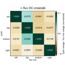
.4 DC-flux crosstalk calibration
We calibrated and compensated for DC-flux crosstalk as in braumuller_probing_2022 . We find a non-negligible crosstalk of around 2%. The full crosstalk matrix for the -flux device is shown in Supplementary Information Fig. S1; the crosstalk matrix for the zero-flux device is similar.
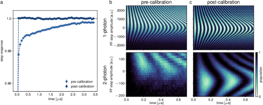
.5 Fast-flux calibration
The fast-flux pulses used to tune qubit frequencies during the experimental sequence ideally have step-function responses. We calibrated for long-time deviations from the ideal step pulse as in ma_dissipatively_2019 and short-time deviations as in braumuller_probing_2022 . One and two-photon oscillations between two qubits before and after these compensations are plotted in Supplementary Information Fig. S2.
.6 Qubit tuning into resonance
The four qubits were first biased approximately into resonance using DC-flux currents. To compensate for frequency disorder, we fine-tuned the qubit frequencies using fast-flux pulses through a heuristic algoritm. We first set the bottom qubit to a frequency near its sweet spot and varied the step amplitude of a fast-flux pulse to bring the left qubit into resonance, probed via a single-particle two-qubit walk. Next we brought the top qubit into resonance, probed via the dynamics of a single particle initialized on the left qubit and optimized for balanced measurement probabilities on the top and bottom qubits. Finally, we brought the right qubit into resonance, verified through comparison with simulated plaquette dynamics.
.7 Hamiltonian estimation & simulation
All of the parameters used in the Hamiltonian time-domain simulations were independently measured. To determine tunneling amplitudes between neighboring qubit pairs, we performed a single-particle two-qubit walk with the nonparticipating qubits detuned by at least MHz. This walk was also used to determine approximate dephasing times for the coupled plaquette systems, which have a reduced flux dispersion compared to that of an individual qubit guo_observation_2021 . The coherence time was individually measured at the target frequency. Simulations use the QuTiP package johansson_qutip_2013 .
Extended Data
Supplementary Materials for
Flat-band localization and interaction-induced delocalization of photons
1 Device parameters
| zero flux | flux | |||||||
| qubit | left | top | bottom | right | left | top | bottom | right |
| (GHz) | 26.80(1) | 25.85(1) | 27.69(1) | 26.32(1) | 27.58(1) | 27.01(1) | 27.72(1) | 27.04(1) |
| 0.5954(3) | 0.5962(4) | 0.5922(4) | 0.5897(2) | 0.5897(2) | 0.5941(3) | 0.5770(3) | 0.6029(2) | |
| (MHz) | 158.10(6) | 157.90(5) | 157.80(5) | 157.26(4) | 157.30(2) | 157.56(3) | 158.91(5) | 158.40(7) |
| (MHz) | 4450 | 4450 | ||||||
| (MHz) | 6962.62(1) | 7033.80(1) | 7104.82(1) | 7230.25(1) | 6952.62(1) | 7055.99(1) | 7117.79(1) | 7250.22(1) |
| (MHz) | 0.84(1) | 0.59(1) | 0.81(1) | 0.32(1) | 0.86(1) | 0.54(1) | 0.80(1) | 0.37(1) |
| (MHz) | 64.73(18) | 64.10(4) | 67.16(9) | 64.63(3) | 60.27(13) | 67.86(10) | 68.40(13) | 67.20(9) |
| (us) | 42.4(8) | 42.2(1.0) | 44.1(1.0) | 48.5(1.0) | 50.6(9) | 43.6(7) | 50.4(1.6) | 44.0(1.0) |
| (us) | 2.95(13) | 2.11(9) | 3.44(15) | 3.08(13) | 2.94(10) | 1.82(7) | 1.96(10) | 3.47(18) |
| (us) | 32.6(1.3) | 22.9(1.2) | 32.8(0.9) | 19.2(5) | 27.3(5) | 28.1(6) | 27.9(8) | 27.8(6) |
| (us) | 1.41(12) | 0.89(8) | 1.56(10) | 1.30(14) | 1.59(14) | 0.90(4) | 1.05(10) | 1.84(10) |
Tab. S1 summarizes the device parameters for our zero- and -flux rhombus circuits; however we note that these exact values are not necessary to observe the results presented in the main text. Our independently measured tunnel couplings are in Tab. S2. All qubits are flux-tunable with loop sizes of approximately , with approximately 2.2 mA corresponding to one flux quantum through the loop.
| tunneling | zero flux | flux |
|---|---|---|
| (MHz) | 11.879(1) | 11.781(1) |
| (MHz) | 11.792(1) | 11.884(1) |
| (MHz) | 11.587(1) | 11.736(1) |
| (MHz) | 11.734(1) | 11.238(1) |
The qubit target frequency was chosen to reduce frequency sensitivity to flux bias and optimize qubit coherence. The former consideration merits proximity to a qubit sweet spot, while the second requires avoiding frequency resonances with lossy two-level systems in the device material that are physically proximal to one of the four qubits. For both devices, we select a qubit target frequency of 4.45 GHz.
2 Wiring & setup
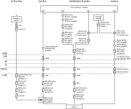
The wiring and measurement setup is in Fig. S1, discussed in the Methods, and is generally similar to the setup used in similar works. We highlight the use of the Xilinx RFSoC ZCU216, with software control through the QICK package stefanazzi_qick_2022 , for arbitrary waveform generation of the fast-flux pulses, qubit drives, and qubit readout probe. This board is also used for signal digitization, greatly simplifying the microwave hardware requirements for the setup. We elaborate also on the modified bias-tee to combine the DC and fast-flux lines in the mixing chamber; here, the capacitor was removed and replaced with a short.
3 Device flux calibrations
We characterize and compensate for both DC-flux crosstalk and distortions in the fast-flux pulse shape, as described in the Methods. The measured DC-flux cross-coupling matrix for the -flux device is shown in Fig. S1; we note that the zero-flux device exhibits a similar matrix.
In Fig. S2 we plot the top qubit response to the fast-flux pulse before and after its calibration. We additionally evaluate the performance of fast-flux pulses through single-particle and doublon walks over two qubits, where the initially excited qubit is brought into resonance with the second qubit via the fast-flux pulse. In these evaluations, the fast-flux pulse amplitude is varied and subsequent excitation population over time measured. Because oscillations are the slowest when the qubits are on resonance, the single-qubit walk reveals imperfections in the fast-flux pulse when the optimal fast-flux amplitude appears to vary over time. Similarly, asymmetric oscillation contrast for fast-flux setpoints above and below resonance reflects imperfections in the fast-flux pulse. We find that both of these effects are qualitatively eliminated post-calibration.
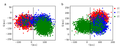
4 Readout Parameters
We determine qubit state occupancy using the state-dependent dispersive shift of the corresponding readout resonator. To calibrate, we initialize the qubit into the , , or state using pulses between adjacent levels and measure the resulting quadrature I/Q signal. Readout tone frequencies, powers, and averaging times are separately optimized for discrimination between the and states, versus the and states. In the single-particle and interacting particle-particle dynamics, we optimize for separability between the and state I/Q signals as seen in Fig. S1a. For the doublon dynamics, we optimize for separability between the and states as seen in Fig. S1b.
We use separately measured readout fidelities for each qubit to correct for readout error on that qubit. Across all four qubits and both devices, the average readout fidelity for distinguishing the from the state is 86(2)% while the average readout fidelity for distinguishing the from the state is 80(2)%. We note the reduced readout fidelity for the second excited state predominantly results from the lower coherence time for higher qubit levels. Higher readout fidelities could be achieved using a near-quantum-limited amplifier macklin_nearquantum-limited_2015 and reduced measurement time.
For simultaneous readout of two qubits, we perform a similar calibration where we initialize in the product states , , , and and concurrently measure the resulting quadrature I/Q signals for the two corresponding readout resonators. The two qubits are detuned from each other to suppress coupling during readout; in particular, nearest neighbors are detuned by at least 200 MHz. These readout frequencies differ from that of single-qubit readout; correspondingly, readout-tone frequencies and powers are reoptimized. The measurement averaging time remains the same. For all qubit pairs, each qubit’s measurement fidelity is independent of the state of the other and consistent with its single-qubit measurement fidelity.
5 Effective Dephasing Rates
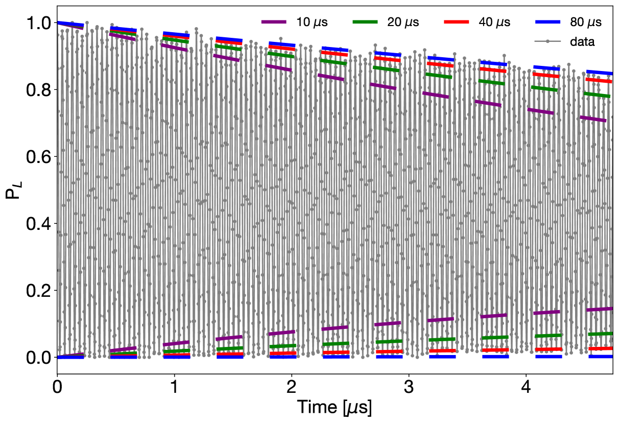
We estimate the effective of our coupled system as in guo_observation_2021 because coupled systems have reduced flux dispersion compared to that of individual qubits. To do this, we use single-photon oscillations between the zero-flux left (L) and bottom (B) qubits when both are tuned to the target qubit frequency. Under the simplification that both qubits have the same effective dephasing rate , the expected left-qubit first-excited-state population over time can be written as:
| (S1) |
for a coupling rate and depolarization times and for the left and bottom qubits, respectively. With our independently measured and values, we vary the dephasing time and compare the exponentially decaying envelope of to measurement as seen in Fig. S1. We find that values between 40 and 80 are consistent with the data. Given that single-qubit times are on the higher end of the values across all eight qubits in both devices, we use 40 as the effective dephasing rate of the coupled system for both devices. For doublon dynamics, we use because the flux dispersion is approximately twice that of the ground-to-first-excited-state transition.
6 Interaction-induced coherent beating
Here we elaborate on the observed beating of oscillations in the measured doublon populations of main text Fig. 3 and particle-particle populations of main text Fig. 4.
These are perhaps best understood through the energy eigenbases of these systems. More specifically, the qualitative models presented in the main text treat the doublon subspace as a decoupled subspace from the particle-particle subspace; however, this is only true in the limit of infinite interaction strength. For finite interactions, the energy eigenstates are hybridized between states in the two subspaces, albeit weakly for strong interactions. Furthermore, this hybridization shifts the eigenstate energies. Then, because the initial Fock states are superpositions of numerous energy eigenstates, time evolution under the Hamiltonian results in differing phase accumulation between the eigenstates, resulting in the coherent beating of population oscillations. We note that the visibility of coherent beating is also a consequence of finite-size effects as there are simply fewer energy eigenstates to cause full dephasing.
We find in the bound two-photon walk, a weak detuning the left or right qubit significantly suppresses the s-timescale beating. Fig. S1 shows the experimentally measured dynamics of a doublon with the right qubit detuned by MHz, along with simulations with and without this detuning for comparison. The sensitivity to detuning suggests that it breaks a degeneracy of the system or further perturbs the eigensystem in a way that reduces the observed beating effect.
7 Photon-photon dynamics
In the main text, we qualitatively represent the interacting particle-particle walk through the Hamiltonian adjacency graph. Each state in the Fock-state subspace is treated as a site, with coupling strengths and signs inherited from the interacting two-particle Hamiltonian. Time evolution of an initial Fock state in the Hamiltonian, then, corresponds to single-particle evolution on the graph, initialized on the corresponding site. We note that such approaches can also be used to experimentally simulate interacting particle systems zhou_observation_2023 ; however they scale unfavorably with particle number.
An alternative approach to understanding the interacting particle-particle walk examines the eigenstates of the Fock-state subspace as depicted in Fig. S1. The zero-flux plaquette eigenspectrum exhibits three energies, each of which has an eigenstate (outlined in yellow) that has nonzero overlap with the Fock state: that is, nonzero overlap with the initial state of a particle on the left site and a particle on the right site. Time evolution of the superposition of these states results in nonzero probability amplitudes of all Fock states in this subspace at some point in time. With flux, the eigenspectrum still exhibits three distinct energy values, only two of which have eigenstates that overlap with . Furthermore, they both have zero probability amplitude of the state. As a result, we do not expect to simultaneously observe a particle on the top site and a particle on the bottom site at any point in time (in the limit of zero disorder and dephasing).
8 Increasing particle number
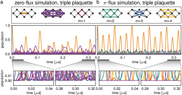
Here we consider particle number on the -rhombus plaquette. Figure S1a shows the eigenenergies for to particles on the plaquette for a ratio of interaction strength to tunneling of , which is the approximate ratio of our experimental devices. For a given particle number, the eigenenergies are largely grouped around integer values of the interaction energy . Correspondingly, the grouped eigenstates approximately reflect different Fock-state partitions of the particles over the four sites, labeled in the subfigure. For example, particles can be partitioned by placing all three particles on one site (“3”, with four Fock states); two particles on one site and one particle on a different site (“2+1”, with twelve Fock states), or all three particles on unique sites (“1+1+1”, with four Fock states). Because interactions are the dominant energy of the system, the respective eigenenergies are then close to , , and (due to three, two, and no interacting particles on one of the sites). At the same time, we are not strictly in the hard-core limit of infinite interaction strength; as a result, these partition subspaces are not completely uncoupled and there is weak hybridization between them. In other words, the eigenstates labelled with a given partition do contain nonzero overlap with Fock states of different partitions.
We numerically simulate the dynamics of initial Fock states within each of these partitions to examine whether real-space or Fock-space caging occurs. For finite interactions , we first consider dynamics across the entire Hilbert space. We find that within each Fock-space partition there exists at least one initial Fock state for which real-space or Fock-space caging occurs (see Fig. S1b). This caging can be understood through examining the corresponding Hamiltonian adjacency graphs for the entire Hilbert space; Fig. S1c shows the graphs for and . Furthermore, this ubiquitous caging property persists for all nonzero interaction strengths.
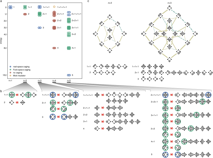
Next we consider the hard-core limit: for a given initial Fock state, we determine whether it explores all other Fock states within the partition subspace. If at least one Fock state within a partition experiences caging, the entire subspace is labelled as exhibiting the caging property. In these characterizations, we label real-space caging as caging that is evident through average single-site measurements over all four sites. Fock-space caging is then caging that is only evident through average two- or multi-site measurements over all four sites. For example, the 1+1+1 subspace can be understood in the hard-core limit by considering the motion of the single hole, rather than the three particles. In this case, the single hole experiences caging, and (as in main text Fig. 2) measurements of a single site at a time are sufficient to identify such caging. The results are color-coded in Fig. S1a and the states that are real-space (Fock-space) caged are outlined in blue (green) in Fig. S1b. Here, we find a general pattern where odd values of exhibit some form of caging within each subspace, while even values of largely do not, a possible generalization from the single-particle caging and doublon escape discussed in the main text.
The real-space caged subspaces can be straightforwardly understood: to begin, the partitions of all particles on one site ( odd) behave as a single composite particle that sees flux through the plaquette and are therefore caged. The other subspaces can be understood in relation to the Mott insulator case for where particles cannot tunnel because every site is occupied. With this in mind, the real-space caging within the 2+1+1+1 subspace can be described by the motion on a single particle on the Mott insulator background; similarly, the real-spacing caging of the 1+1+1 subspace can be thought of as the caging of a hole placed in the Mott insulator.
The Fock-space caged subspaces also contain a rich structure. For odd , each caged state seems to be caged from exactly one other state in its subspace. Furthermore, the two states are related by a 180-degree rotation, which results from the symmetry and flux structure of the Hamiltonian adjacency graph. Interestingly, there are Fock-space caged subspaces for even as well, for example the 1+1 subspace for . We predict the corresponding subspaces are also Fock-space caged for even where (mod ), as they are equivalent to two particles on a Mott insulator background (which exists for where (mod )).