Superconducting Diode Effect Sign Change in Epitaxial Al-InAs Josepshon Junctions
Abstract
There has recently been a surge of interest in studying the superconducting diode effect (SDE). The SDE could be observed in systems where the time reversal and inversion symmetries are broken. Here, we observe the SDE in epitaxial Al-InAs Josephson junctions (JJs) with strong Rashba spin-orbit coupling (SOC), and show that this effect strongly depends on the orientation of the in-plane magnetic field. In the presence of strong magnetic field, we observe a change of sign in the SDE. Simulation and measurement of supercurrent suggests that depending on the superconducting widths, , this sign change may not necessarily be related to or topological transitions. We find the strongest sign change in junctions with narrow is consistent with SOC-induced asymmetry of the critical current under magnetic-field inversion, while in wider , the sign reversal could be related to transitions and topological superconductivity.
Nonreciprocity in non-centrosymmetric quantum systems has been well studied in semiconductors as they are essential for the rectification function in electrical diodes and solar cells. A recent breakthrough is the discovery of nonreciprocity in superconductors, which implies a progress towards designing superconducting diodes and has attracted vigorous interests due to its possible application in modern electronic circuits, sensors, and detectors [1, 2, 3, 4, 5, 6, 7, 8]. Nonreciprocal critical currents in superconductors occur when the magnitude of the critical supercurrent, , depends on the direction in which the current is swept. Theoretically, the so-called diode effect can occur when both inversion and time reversal symmetries are broken, where the latter can be achieved by magnetic proximity effect, in magnetic Josephson junctions, or by applying an external magnetic field. This effect has been attributed to the presence of finite-momentum Cooper pairs and the change in the nature of superconductivity [9, 10, 7, 11, 12]. Recent studies have suggested the existence of the SDE in JJs with large Rashba SOC [2, 13, 14, 6, 1, 5, 15]. The magnitude of the supercurrent in JJs with SOC depends on the direction of the magnetic field, as the Rashba and Dresselhaus effects can have different contributions [16, 17]. Therefore, investigating the SDE through a JJ can provide information about the SOC in its semiconductor.
Planar JJs fabricated on epitaxial Al-InAs heterostructures are great candidates to study SDE due to their strong SOC [18, 3, 2]. Such devices have also shown signatures of topological phase transition when their time reversal symmetry is broken by an in-plane magnetic field [19, 20, 21]. Recently, Costa et al. [13] have reported a sign reversal of the AC SDE in multi-channel JJs based on Al-InAs with strong SOC subjected to a magnetic field, and related it to a -like transition induced by the Zeeman interaction in the device. Conversely, Banerjee et al. [21] have proposed a SDE originating from finite-momentum Cooper pairing solely due to orbital effects, without invoking SOC or Zeeman interaction.
In this work, we study epitaxial Al-InAs JJs with various superconductive contact widths, . By applying a magnetic field perpendicular to the current and parallel to the junction, we observe nonreciprocal critical currents due to the finite-momentum Cooper pairing enabled by the coexistence of strong Rashba SOC and the Zeeman interaction. We observe a SOC-induced shift, , of the magnetic field yielding the maximum of the critical current amplitude and use it to estimate the Rashba SOC strength in the JJ. In the absence of the magnetic field, time-reversal symmetry is restored and the SDE vanishes. However, the SDE can also vanish at certain finite magnetic fields and changes sign below the superconductor critical field, . We consider JJs with various superconducting widths, , and observe zeros of the SDE, across which the current difference characterizing the SDE exhibits sign reversals at finite values of the magnetic field. We attribute the sign reversals to i) -like jumps of the ground-state superconducting phase difference for wide and ii) SOC-induced asymmetry of the critical current under magnetic-field inversion with respect to the field-shift, for narrow .
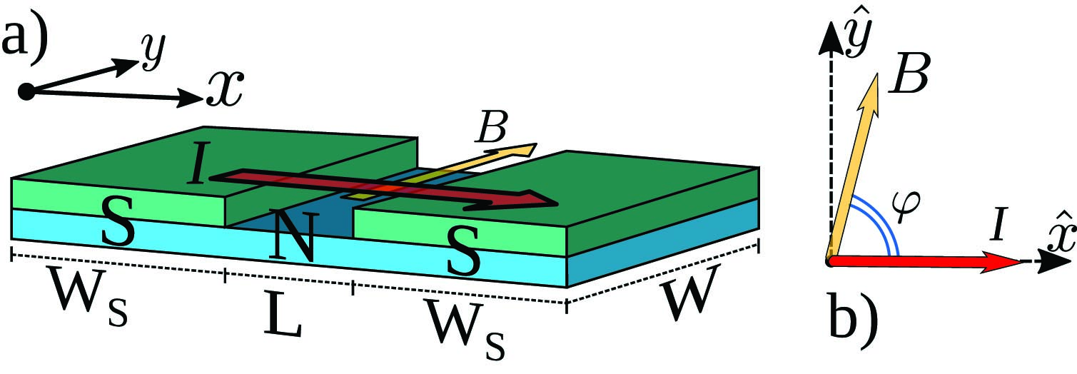
Our junctions are based on epitaxial superconducting Al thin films grown in-situ on InAs heterostructures by molecular beam epitaxy on a InP substrate followed by a graded buffer layer [18, 22, 23]. Typically, the critical field of thin film of Al is greater than 1 T. Fig. 1(a) shows a general schematic of our planar JJs. We study junctions with varying superconducting widths from to . All the junctions are wide and are fabricated using a transene selective wet etching of Al. Fig. 1(b) shows a false colored scanning electron microscopy (SEM) image of a typical long junction with superconducting width of . The Al induced gap in our junctions is about eV estimated from critical temperature, . The semiconductor-superconductor transparency of our junctions are reported in our previous works [24, 25, 26] and can host modes with near unity transparency. We present the data from junctions with (JJ1), and (JJ2) in the main text and provide the additional measurements on three more junctions in the Supporting Information (SI). All the measurements in this study are performed at T in a dilution refrigerator equipped with a three-axis vector magnet. As shown in Fig. 1(b), the -axis of the magnet is perpendicular to the sample plane, while and -axes are in-plane components aligned parallel to the current and junction, respectively.
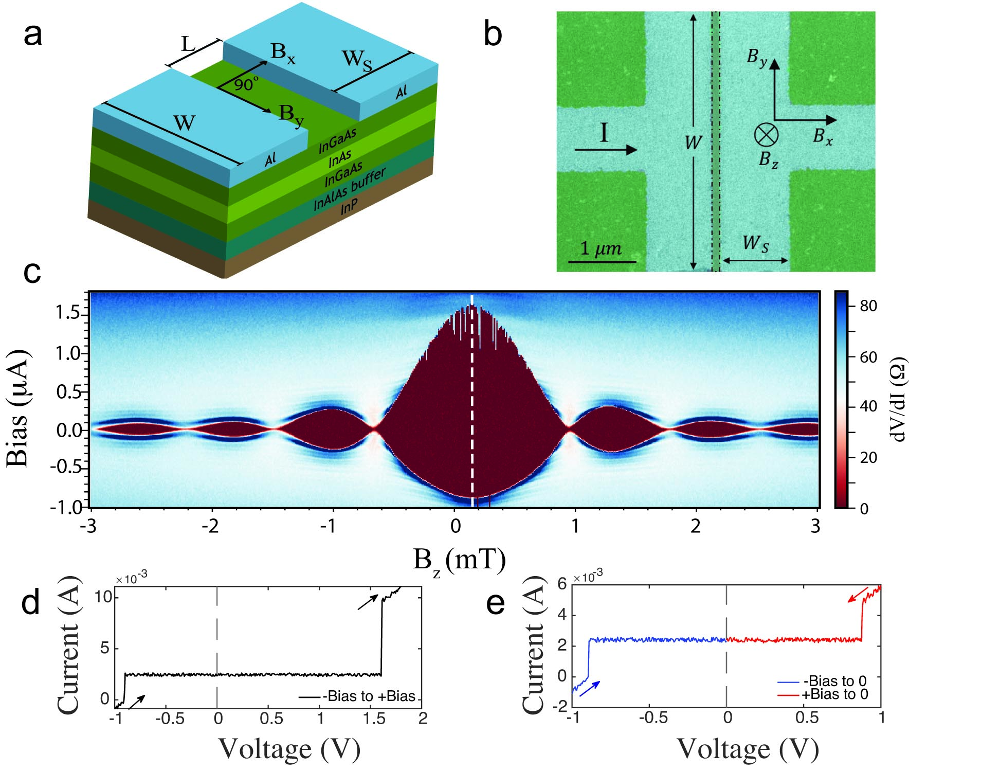
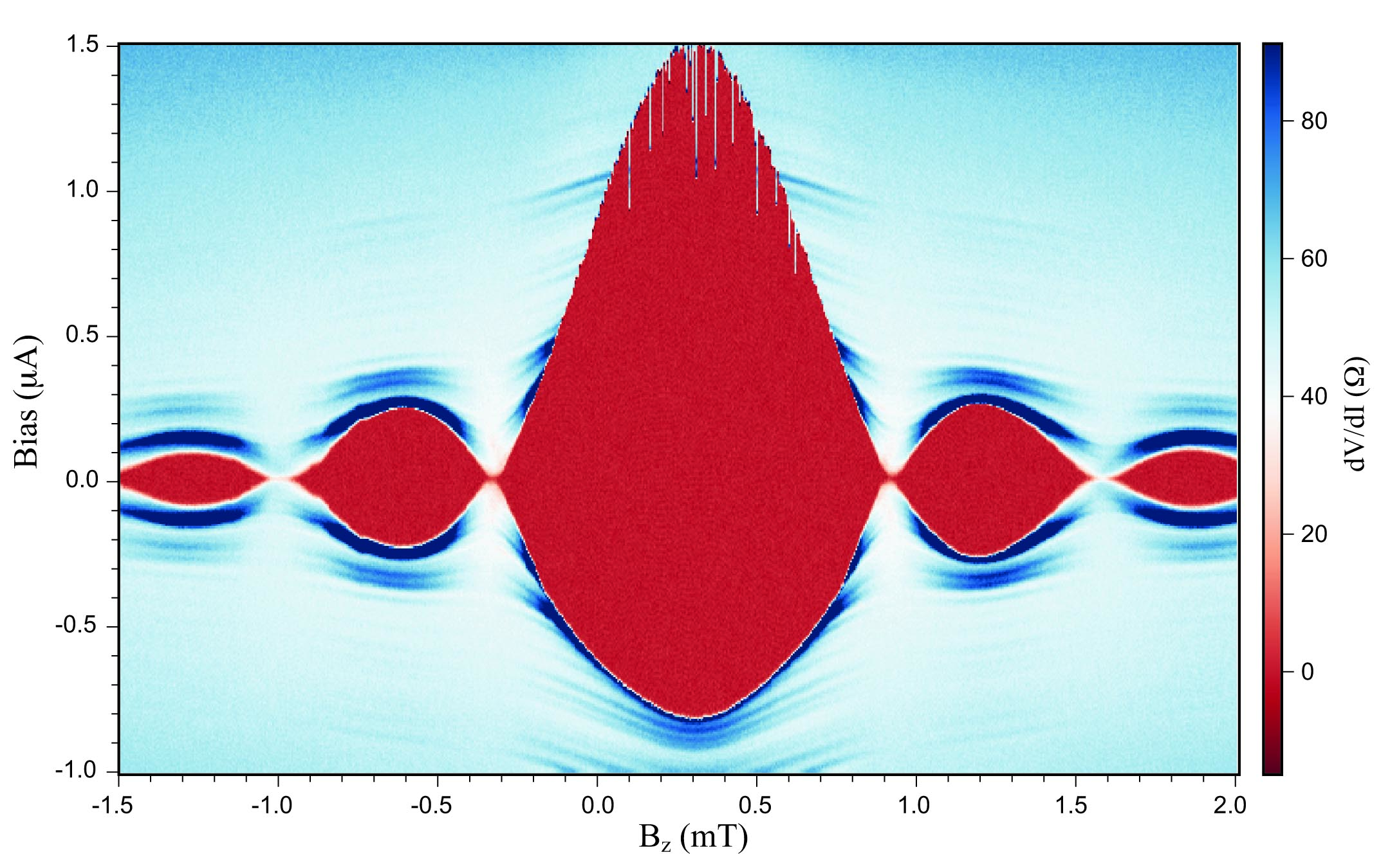
Fig. 1(c) presents the differential resistance as a function of the bias current and applied out-of-plane magnetic field for JJ1 with when the in-plane field is set to zero. The observed Fraunhofer pattern shows a hysteresis due to heating effects when bias is swept through zero [27, 24]. The critical current of the hot electrons branch, where the bias goes from high bias to zero, is clearly smaller than the critical current of the cold electrons branch going from zero to high bias. This is due to the difference between the effective electronic temperature of the hot and cold electrons branches before the transition to or out of the superconducting state. Such a hysteretic behavior leads to different values of critical current on each side, as can be observed in Fig. 1(d) for JJ1, and has to be avoided for accurate SDE measurements. For the rest of this study, we only derive the values of the critical current from the hot electrons branch, going from high bias to zero bias as shown in Fig. 1(e). These two values are expected to be equal for both directions in reciprocal measurements of a conventional device without presence of in-plane magnetic field.
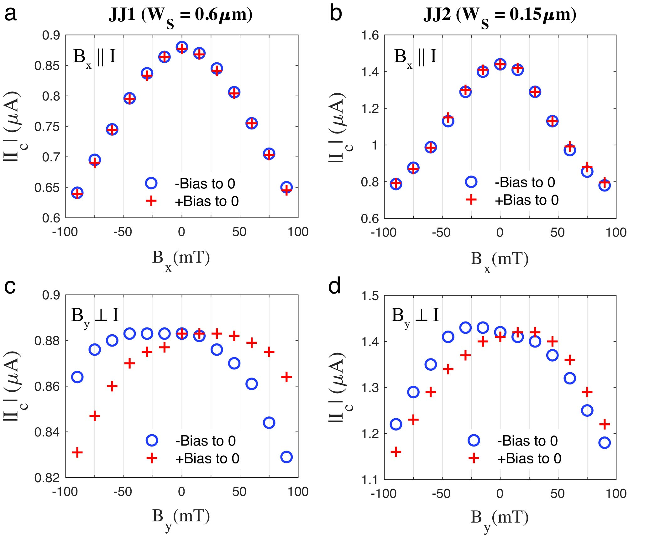
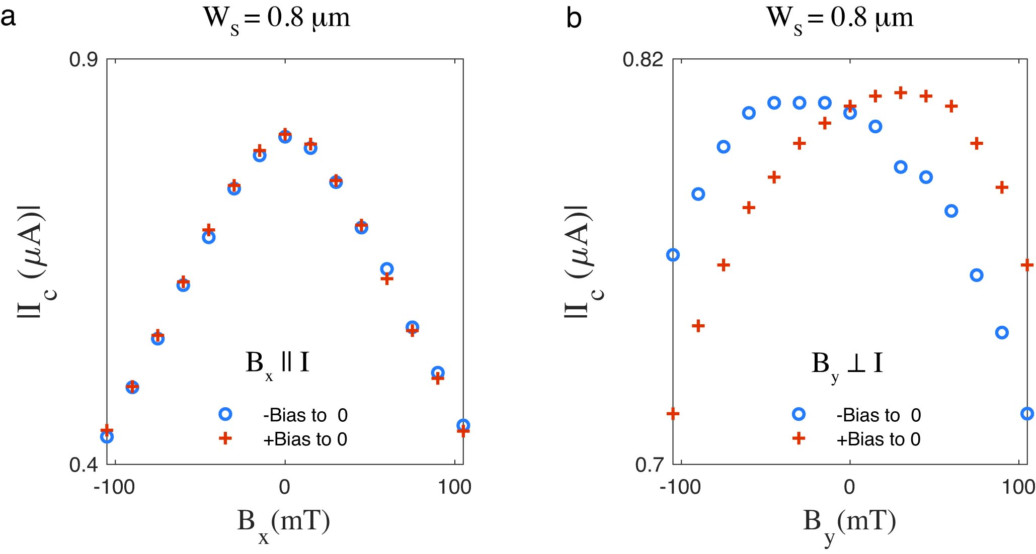
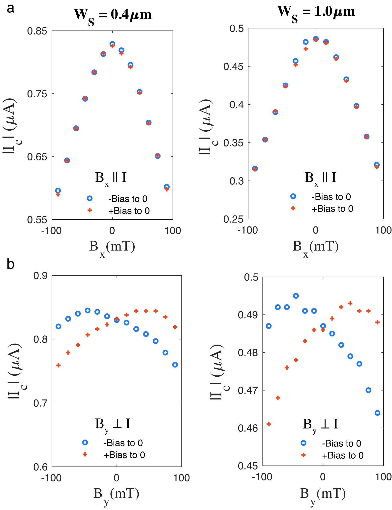
By carefully aligning the magnet directions to Josephson junction and eliminating unwanted out-of-plane component of magnetic field (), we measure the critical current in the presence of an in-plane magnetic field. Fig. 2(a) and (b) show the measured magnitude of the critical current for JJ1 and JJ2 when 0 T and the in-plane magnetic field with strength is parallel to the current. Blue circles and red cross marks correspond to measurement of the magnitude of the critical current when the bias is swept from negative high bias to zero and from positive high bias to zero, respectively. We find that the magnitude of the critical current in both directions is the same and there is no sign of nonreciprocity when the applied in-plane magnetic field is parallel to the current. The absence of SDE when the field is parallel to the current indicates that the dominant SOC in the junctions is of Rashba type, which is in agreement with our previous works [22, 28].
When the in-plane magnetic field is applied perpendicular to the current, in the -direction, we find a difference between the forward and reverse critical currents. Fig. 2(c) and (d) show the dependence of the absolute value of critical current on for JJ1 and JJ2. We observe a clear nonreciprocal behavior, where the critical current is larger for positive than for negative bias when . This behaviour is reversed when the in-plane field direction is flipped to , in agreement with the theoretically expected symmetry relation . Details of the experimental measurements and analyses are given in SI. We extract at each in-plane magnetic field from the maximum of the Fraunhofer pattern at that field. The same measurements were done on three additional devices with , and and showed the same results, as presented in Fig. S5 and S6 of the SI. Those devices exhibit the same behavior as JJ1 and JJ2. In all cases we observe a shift, in the magnetic fields at which the critical currents reach their maximum values when . The shift is positive () for the critical current corresponding to positive bias and negative () for the case of negative bias.
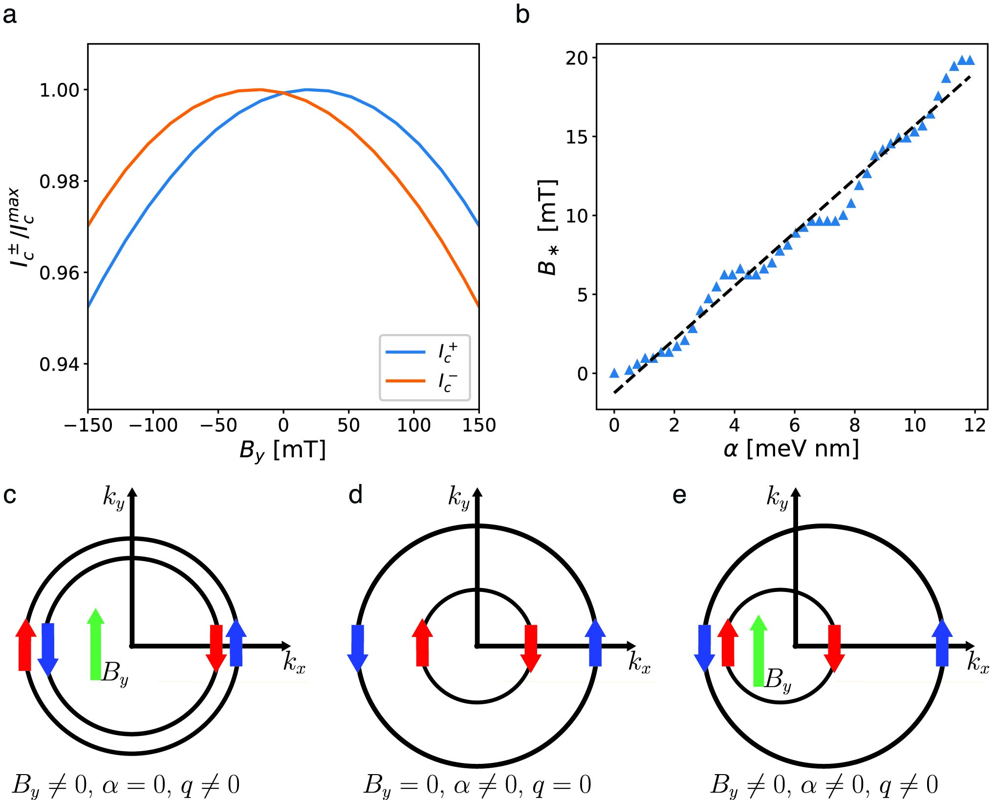
This behavior is captured by our numerical tight-binding simulations (see details in SI). The result of the tight-binding simulation in Fig. 3(a) for a junction with clearly shows the superconducting diode effect in the splitting of , as well as the symmetry with respect to the sign of . Moreover, indicates the presence of SOC in the junction and obeys the symmetry relation, , where denotes the strength of the Rashba SOC. The -dependence of , obtained from the numerical simulations, is shown in Fig. 3(b). The black, dashed line is just a linear fit to guide the eye. Using the field-shift value extracted from the experimental data from our devices, the Rashba SOC strength is in range of 8-12 meV nm in our junctions. These values are in overall agreement with values of in InAs extracted through weak antilocalization measurements [22, 28].
Complementary to the numerical simulations, we provide approximate analytical expressions for the normalized critical currents at low field,
| (1) |
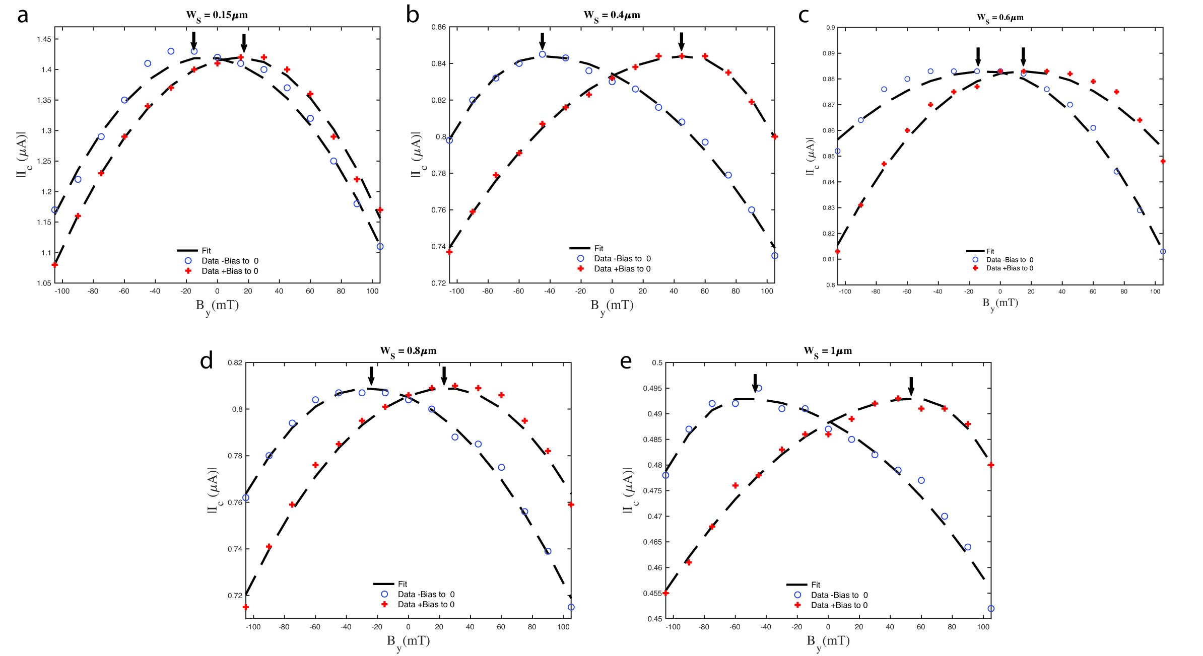
where is the maximum absolute value of the critical current, , , and is the magnitude of the field at which is maximum. Here is the effective g-factor, the Bohr magneton, the Fermi wavevector, the Thouless energy, the Fermi velocity, and , with representing the effective mass. Equation (1) was obtained in the limits where is the superconducting coherence length and . Therefore it is not in quantitative agreement with finite in experimental devices. However, Eq. (1) can provide a qualitative description of the main trends exhibited by the critical currents. In fact, Eq. (1) reproduces well the functional behavior of the experimental data at low field. Fig. S7 shows the experimental data of all the junctions (red and blue marks) fitted to Eq. (1) (dash lines) using , and as fitting parameters.
Our experimental data together with numerical simulation suggest that the observed SDE originates from the finite-momentum Cooper pairing induced by the shift of the Fermi contours when the Zeeman interaction and the Rashba SOC coexist as shown in Fig. 3(c)-(e). In the regime , where , , and denote the Zeeman energy, the Rashba SOC strength and the Fermi wave vector, respectively, the Fermi contours in the N region can be approximated as,
| (2) |
where , , and and determine the directions of the wave vector and magnetic field with respect to the -axis, respectively. The -component of the total momentum of the pairs is,
| (3) |
and the Cooper pair wave function across the junction can be approximated as,
| (4) |
and can be rewritten in terms of singlet, and triplet, components [29],
| (5) |
For , an inversion of the magnetic field orientation reverses the direction of the Fermi contours shift without affecting the spin orientation. Therefore, the coexistence of the singlet and triplet components in the presence of SOC breaks the inversion symmetry of the wave function with respect to the magnetic field direction, resulting in a non-reciprocal response with distinct forward and reverse critical currents. However, the SDE vanishes when the magnetic field is oriented along the -axis (see upper row of Fig. 2) for in this case and in Eq. (3).
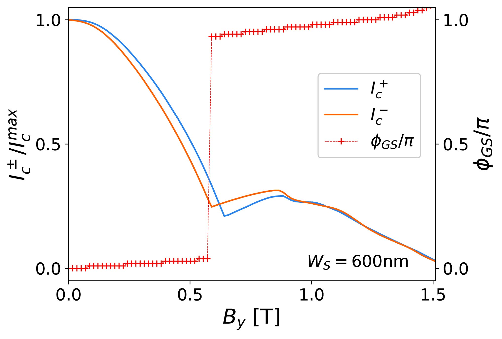
To further study the SDE in our junctions, we investigate the nonreciprocity of the critical currents at higher in-plane magnetic fields perpendicular to the current () in the devices JJ1 and JJ2. Fig. 4(a) and (b) show the absolute value of the critical currents for each junction as a function of . A dip and peak in of JJ1 is observed around . Previous studies have suggested such a behavior can be related to the closing and reopening of the superconducting gap [30, 20] and a topological phase transition. Our numerical simulations exhibit a phase transition at magnetic field near 0.6 T for m as shown in Fig. S9. In contrast, JJ2 data does not show a suppression of supercurrent in Fig. 4(b). Numerical simulations also do not show a phase transition for the ground state of JJ2 with m below 1 T as shown in Fig. S10. .
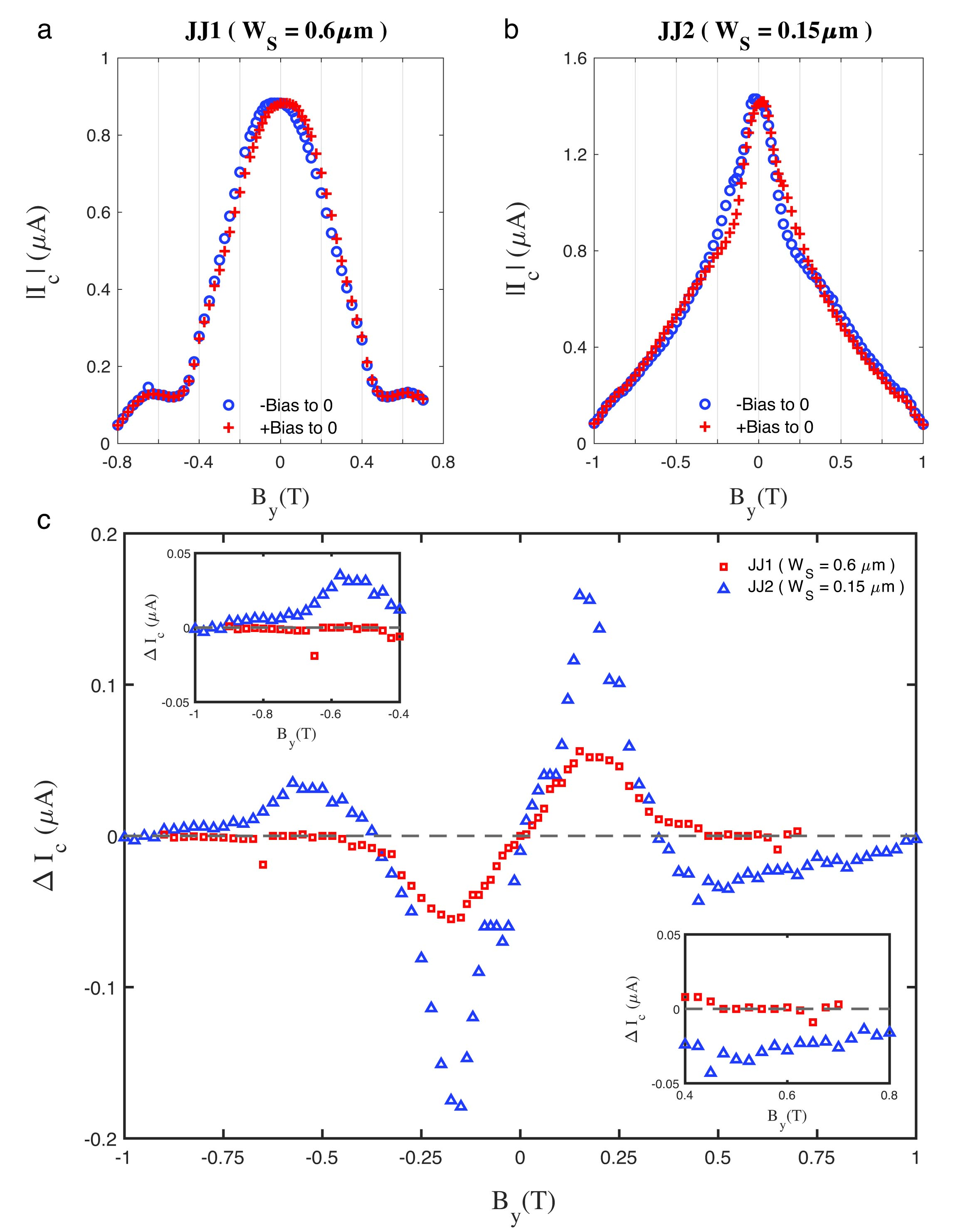
Fig. 4(c) plots the difference between the absolute values of the critical currents for positive and negative biases , as a function of . The results evidence the anti-symmetric character of , which for both junctions changes its sign when the magnetic field is inverted. However, also exhibit zeros at certain values of , across which sign reversals not related to magnetic field inversion are observed. This is particularly apparent for the device JJ2 (blue symbols) at fields T, as shown in Fig. 4(c).
From a comparison between the experimental results and the numerical simulations, we identify two possible mechanisms responsible for the zeros of and their associated SDE sign reversals. According to Eq. (1), the SOC induces an asymmetry in the critical currents under the magnetic field inversion with respect to , with . This asymmetry is apparent in Fig. 2(c)-(d) and Fig. 4(a)-(b). The coexistence of a finite magnetic shift, , and a strong SOC-induced critical current asymmetry can cause and to cross at a finite magnetic field and produce a sign reversal in the SDE without involving -like transitions. This situation is apparent in JJ2 from Fig. 4(b) and (c), where a critical current crossing and corresponding sign reversal of at T are observed, respectively. The numerical simulations are in good agreement with the experimental data of JJ2, predicting a critical current crossing at T, which is unrelated to the transition at T (see Fig. S10 in SI).
As discussed above, the SDE originates from finite-momentum Cooper pairing qualitatively described by a wave function lacking inversion symmetry with respect to when both Rashba SOC and Zeeman interaction are present. However, it follows from Eq. (5) that the inversion symmetry with respect to is reestablished when either the singlet or triplet component vanishes at the S/N interfaces located at and , i.e., when , where is an integer number. Therefore, junctions with exhibit zeros of when,
| (6) |
The re-scaling factor has been introduced to account for the fact that the Zeeman field is likely present over the whole system and not only in the semiconductor region.
The zeros (and their associated SDE sign reversals) corresponding to odd integers in Eq. (6), say (with an integer), can be associated with -like transitions the junction would experience close to equilibrium. Indeed, in the absence of currents, the superconducting phase difference self-tunes to a value (referred to as the ground-state phase difference) that minimizes the free energy of the system. For the singlet component of the wave function at the two superconducting leads has the same sign, indicating that . However, when [i.e., ], the ground-state phase jumps from 0 to and the singlet at the two superconducting leads acquire opposite signs for . Therefore, SDE sign reversals corresponding to odd values of in Eq. (6) are associated to -like (or -like) transitions, while additional sign reversals are expected to occur between and -like transitions, when is even. The -like ground-state phase jump has been identified as a possible signature of topological phase transitions in planar JJs [30, 20]. Hence, the nodes of corresponding to odd may indirectly signal a transition into the topological superconducting state. However, such a signature is not conclusive, especially in JJs with narrow superconducting leads, where ground-state phase jumps are not necessarily associated to topological phase transitions [31, 32].
The numerical simulations for devices JJ1 and JJ2 reveal -like jumps of the ground-state phase at T and T, respectively [see Figs. S9 and S10(b) in SI], suggesting that if the changes sign at higher fields [see insets in Fig. 4(c)] they could be associated to -like transitions with . However, we find that the measured current difference, , is too small in experiment and is difficult to conclusively establish the existence of these sign reversals in range of 0.6 T to 1 T.
In summary, we have studied the superconducting diode effect in epitaxial InAs/Al Josephson junctions with different superconducting width and showed that the SDE depends on the orientation of the applied in-plane magnetic field in the system. By measuring the supercurrent of the junction, we observe SDE only when the in-plane field is perpendicular to the current. We observe a shift in magnetic field yielding the maximum critical current and obtain an analytical expression describing the critical current behavior at low magnetic field. We propose a method for estimating the Rashba parameter from the measurement of the magnetic field shift of the SDE and numerical simulations. The results are in good agreement with values previously reported for our system. We also measure the SDE at high magnetic fields and observe a sign change in the of the junction at T. Using our Tight binding simulation, we conclude that this sign change is not necessarily an indicator of or topological transitions in the system.
This work is supported in part by DARPA Topological Excitations in Electronics (TEE) program under grant No. DP18AP900007, the U.S. Office of Naval Research (ONR) through Grants No. N000142112453 and MURI No. N000142212764.
References
- Ando et al. [2020] F. Ando, Y. Miyasaka, T. Li, J. Ishizuka, T. Arakawa, Y. Shiota, T. Moriyama, Y. Yanase, and T. Ono, Nature 584, 373 (2020).
- Baumgartner et al. [2022a] C. Baumgartner, L. Fuchs, A. Costa, J. Picó-Cortés, S. Reinhardt, S. Gronin, G. C. Gardner, T. Lindemann, M. J. Manfra, P. E. Faria Junior, D. Kochan, J. Fabian, N. Paradiso, and C. Strunk, Journal of Physics: Condensed Matter 34, 154005 (2022a).
- Baumgartner et al. [2022b] C. Baumgartner, L. Fuchs, A. Costa, S. Reinhardt, S. Gronin, G. C. Gardner, T. Lindemann, M. J. Manfra, P. E. Faria Junior, D. Kochan, J. Fabian, N. Paradiso, and C. Strunk, Nature Nanotechnology 17, 39 (2022b).
- Bauriedl et al. [2022] L. Bauriedl, C. Bäuml, L. Fuchs, C. Baumgartner, N. Paulik, J. M. Bauer, K.-Q. Lin, J. M. Lupton, T. Taniguchi, K. Watanabe, C. Strunk, and N. Paradiso, Nature Communications 13, 4266 (2022).
- Wu et al. [2022] H. Wu, Y. Wang, Y. Xu, P. K. Sivakumar, C. Pasco, U. Filippozzi, S. S. P. Parkin, Y.-J. Zeng, T. McQueen, and M. N. Ali, Nature 604, 653 (2022).
- Pal et al. [2022] B. Pal, A. Chakraborty, P. K. Sivakumar, M. Davydova, A. K. Gopi, A. K. Pandeya, J. A. Krieger, Y. Zhang, M. Date, S. Ju, N. Yuan, N. B. M. Schröter, L. Fu, and S. S. P. Parkin, Nature Physics 18, 1228 (2022).
- Yuan and Fu [2022] N. F. Q. Yuan and L. Fu, Proceedings of the National Academy of Sciences 119, e2119548119 (2022).
- Wakatsuki et al. [2017] R. Wakatsuki, Y. Saito, S. Hoshino, Y. M. Itahashi, T. Ideue, M. Ezawa, Y. Iwasa, and N. Nagaosa, Science Advances 3, e1602390 (2017).
- Davydova et al. [2022] M. Davydova, S. Prembabu, and L. Fu, Science Advances 8, eabo0309 (2022).
- Daido et al. [2022] A. Daido, Y. Ikeda, and Y. Yanase, Physical Review Letters 128, 037001 (2022).
- Ilic and Bergeret [2022] S. Ilic and F. Bergeret, Physical Review Letters 128, 177001 (2022).
- He et al. [2022] J. J. He, Y. Tanaka, and N. Nagaosa, New Journal of Physics 24, 053014 (2022).
- Costa et al. [2022] A. Costa, C. Baumgartner, S. Reinhardt, J. Berger, S. Gronin, G. C. Gardner, T. Lindemann, M. J. Manfra, D. Kochan, J. Fabian, N. Paradiso, and C. Strunk, arXiv:2212.13460 (2022).
- Turini et al. [2022] B. Turini, S. Salimian, M. Carrega, A. Iorio, E. Strambini, F. Giazotto, V. Zannier, L. Sorba, and S. Heun, Nano Letters 22, 8502 (2022).
- Jeon et al. [2022] K.-R. Jeon, J.-K. Kim, J. Yoon, J.-C. Jeon, H. Han, A. Cottet, T. Kontos, and S. S. P. Parkin, Nature Materials 21, 1008 (2022).
- Pakizer et al. [2021] J. D. Pakizer, B. Scharf, and A. Matos-Abiague, Phys. Rev. Res. 3, 013198 (2021).
- Pekerten et al. [2022] B. Pekerten, J. D. Pakizer, B. Hawn, and A. Matos-Abiague, Phys. Rev. B 105, 054504 (2022).
- Shabani et al. [2016] J. Shabani, M. Kjaergaard, H. J. Suominen, Y. Kim, F. Nichele, K. Pakrouski, T. Stankevic, R. M. Lutchyn, P. Krogstrup, R. Feidenhans’l, S. Kraemer, C. Nayak, M. Troyer, C. M. Marcus, and C. J. Palmstrøm, Physical Review B 93, 155402 (2016).
- Fornieri et al. [2019] A. Fornieri, A. M. Whiticar, F. Setiawan, E. Portoles, A. C. C. Drachmann, A. Keselman, S. Gronin, C. Thomas, T. Wang, R. Kallaher, G. C. Gardner, E. Berg, M. J. Manfra, A. Stern, C. M. Marcus, and F. Nichele, Nature 569, 89 (2019).
- Dartiailh et al. [2021a] M. C. Dartiailh, W. Mayer, J. Yuan, K. S. Wickramasinghe, A. Matos-Abiague, I. Žutić, and J. Shabani, Physical Review Letters 126, 036802 (2021a).
- Banerjee et al. [2023] A. Banerjee, M. Geier, M. A. Rahman, C. Thomas, T. Wang, M. J. Manfra, K. Flensberg, and C. M. Marcus, arXiv:2301.01881 (2023).
- Wickramasinghe et al. [2018] K. S. Wickramasinghe, W. Mayer, J. Yuan, T. Nguyen, L. Jiao, V. Manucharyan, and J. Shabani, Applied Physics Letters 113, 262104 (2018).
- Strickland et al. [2022] W. M. Strickland, M. Hatefipour, D. Langone, S. M. Farzaneh, and J. Shabani, Applied Physics Letters 121, 092104 (2022).
- Mayer et al. [2019] W. Mayer, J. Yuan, K. S. Wickramasinghe, T. Nguyen, M. C. Dartiailh, and J. Shabani, Applied Physics Letters 114, 103104 (2019).
- Mayer et al. [2020] W. Mayer, M. C. Dartiailh, J. Yuan, K. S. Wickramasinghe, E. Rossi, and J. Shabani, Nature Communications 11, 212 (2020).
- Dartiailh et al. [2021b] M. C. Dartiailh, J. J. Cuozzo, B. H. Elfeky, W. Mayer, J. Yuan, K. S. Wickramasinghe, E. Rossi, and J. Shabani, Nature Communications 12, 78 (2021b).
- Courtois et al. [2008] H. Courtois, M. Meschke, J. T. Peltonen, and J. P. Pekola, Physical Review Letters 101, 067002 (2008).
- Farzaneh et al. [2022] S. M. Farzaneh, M. Hatefipour, W. F. Schiela, N. Lotfizadeh, P. Yu, B. H. Elfeky, W. M. Strickland, A. Matos-Abiague, and J. Shabani, Magneto anisotropic weak antilocalization in near surface quantum wells (2022), arXiv:2208.06050 [cond-mat].
- Eschrig [2015] M. Eschrig, Rep. Prog. Phys. 78, 104501 (2015).
- Pientka et al. [2017] F. Pientka, A. Keselman, E. Berg, A. Yacoby, A. Stern, and B. I. Halperin, Phys. Rev. X 7, 021032 (2017).
- Setiawan et al. [2019] F. Setiawan, A. Stern, and E. Berg, Phys. Rev. B 99, 220506(R) (2019).
- Pakizer and Matos-Abiague [2021] J. D. Pakizer and A. Matos-Abiague, Phys. Rev. B 104, L100506 (2021).
- Groth et al. [2014] C. W. Groth, M. Wimmer, A. R. Akhmerov, and X. Waintal, New J. Phys. 16, 063065 (2014).
I Supporting Information
II Experimental details and further data
II.1 2DEG structure and characterization
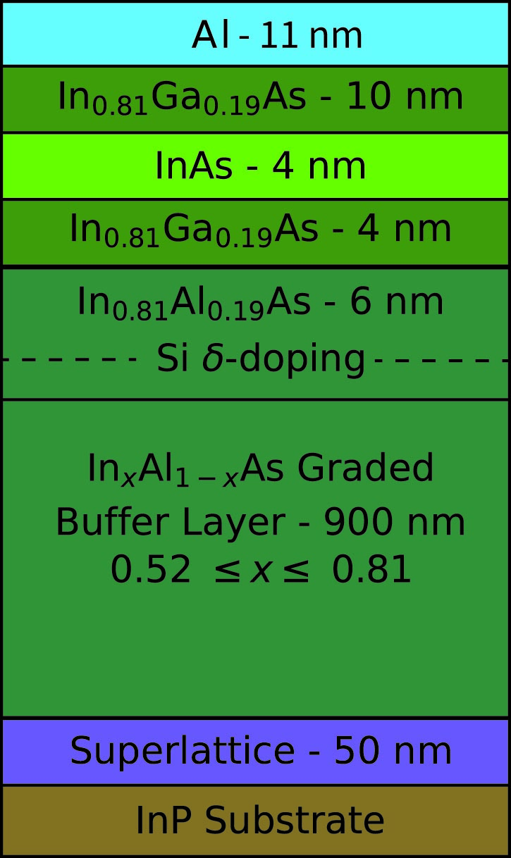
The heterostructure is grown by molecular beam epitaxy on a graded buffer layer over a semi-insulating InP (100) substrate. For optimal semiconductor-metal interface and a high mobility two-dimensional electron gas (2DEG), the quantum well consists of a 4 nm layer of InAs grown between two layers of 4 and 6 nm of In0.81Ga0.19As. The quantum well material stack of the heterostructure is presented in Fig. S1. By measuring Hall bars fabricated on the 2DEG, the electron density is measured to be cm-2 and the mobility is calculated to be cm2/V.s.
II.2 Fabrication details
The devices were fabricated by electron beam lithography using spin-coated PMMA resist. The mesa features were defined by a wet etch down to the buffer layer using a III-V etchant consisting of phosphoric acid (H3PO4, 85%), hydrogen peroxide (H2O2, 30%) and deionized water in a volumetric ratio of 1:1:40. The junction gap and contacts were defined by removing Al using the Transene Al etchant type D.
II.3 Measurements details
All the measurements are performed in an Oxford Triton dilution refrigerator equipped with a three-axis vector magnet at T mK. All out-of-plane field measurements are performed by sweeping from negative field to positive field. Due to static remnant field in the vector magnet coils, the maximum of the critical current could be shifted slightly from 0 mT. The true zero perpendicular field is determined through maximum of Fraunhofer peak and follow its evolution in presence of in-plane magnetic field.
Standard dc and lock-in techniques are performed in a four-point geometry at low frequencies (17Hz) with current excitation of = 10 nA using a current-biased configuration by sweeping and measuring differential resistance using an SRS860 lock-in amplifier. We measure the critical current at which the junction switches from the superconducting to the normal resistive state.
II.4 Superconducting diode effect measurements
Fig. S2 presents the differential resistance as a function of the bias current and out-of-plane magnetic field of JJ3 with at zero in-plane magnetic field. The junction shows hysteresis, but as discussed in the main text and our previous work [24], this hysteresis is due to thermal effects [27]. There are no lifted nodes in the interference pattern in Fig. S2 and the critical current reaches precisely zero for all the nodes. All of our junctions have similar Fraunhofer patterns in the presence of in-plane magnetic fields.
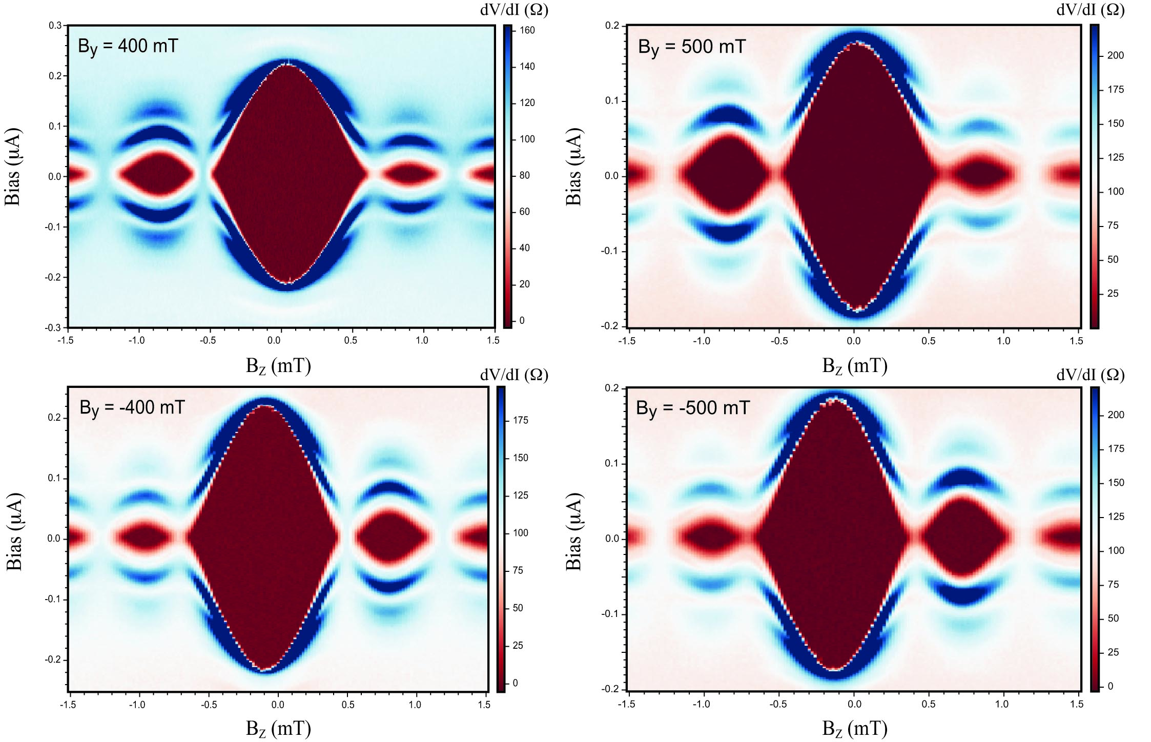
Fig. S3 presents the Fraunhofer patterns of JJ3 at different in-plane magnetic fields, . Using these data, we correct the three axes of the magnet to remove residual out-of-plane components from in-plane vector magnets. Due to static remnant field in the vector magnet coils, the maximum of the critical current might get slightly shifted from = 0 mT. To make sure that the diode effect measurements are done at precisely zero out-of plane magnetic field and cancel shifts in the magnet alignments, all the SDE measurements in this study are performed on the main lobe of the Fraunhofer pattern.
The main lobes of Fraunhofer patterns for JJ3 in the presence of in-plane magnetic fields from to are shown in Fig. S4. The left columns present the data when the bias is swept from negative to zero and the right columns are when the bias is swept from positive to zero. The supercurrent of each plot is extracted at the maximum of the Fraunhofer and plotted in Fig. S5(b). The same measurements are done for and shown in Fig. S5(a). All the measurements in this paper are conducted with the same method. Although these type of measurements take a great deal of time, they lead to reproducible results. Fig. S6 shows the data for two additional junctions measured using the same method. The SDE can be seen in all these junctions when the in-plane magnetic field is but no SDE when .
Fig. S7 shows the fit (black dashed lines) from equation (1) of the main text to the measured absolute value of critical current (blue and red marks) for all the junctions as a function of in-plane magnetic field perpendicular to the current. Here, , and and are fit parameters. Although equation (1) was derived for a junction with , it can describe the SDE of a device with finite at low magnetic fields very well. Black arrows show the position of the derived from the fit. We can see that for junctions with , , and is approximately 15 mT. However it has a lager value for the junctions with , and . This could be due to the junction geometry or a different SOC in these devices.
![[Uncaptioned image]](/html/2303.01902/assets/FigureS4a.jpg)
![[Uncaptioned image]](/html/2303.01902/assets/FigureS4b.jpg)

III Theoretical model
We consider an InAs-Al planar Josephson junction (JJ) with the geometry shown in Fig. S8. The system is described by the Bogoliubov-de Gennes (BdG) Hamiltonian,
| (7) |
where, is the single-particle Hamiltonian of the 2DEG in the presence of Rashba spin-orbit coupling (SOC), is the Zeeman interaction and the last two terms model the superconducting pairing in the S regions. The term is the single-particle kinetic energy with as the momentum and the effective mass, is the chemical potential, is the Rashba SOC strength, are the Pauli-matrices in the spin space, and are Nambu matrices in the particle-hole space, and is the minimum of the single-particle energy due to Rashba SOC. In the Zeeman interaction, is the effective g-factor, is the Bohr magneton and is the vector of Dirac spin matrices. The superconducting gap is given by,
| (8) |
where with being the Heaviside step function, , and is the superconducting phase difference across the junction. The magnetic field and temperature dependence are given by the BCS relations,
| (9) |
where is the zero temperature and zero field superconducting gap, is the critical temperature, and , with the zero-temperature critical magnetic field.
We consider a JJ with translational invariance along the -axis. After determining the energy spectrum, of the BdG Hamiltonian, we compute the free energy,
| (10) |
and the current-phase relation,
| (11) |
The forward and reverse critical currents are then calculated as
| (12) |
respectively.
III.1 Analytical approximation
We determine the general form of the Andreev bound states in the S and N regions in the limit . Applying appropriate boundary conditions leads to a system of linear equations. The energy spectrum is then obtained by requiring the system of equations to have non-trivial solutions. The free energies and critical currents are then computed in the zero-temperature limit. The result is then expanded in series up to second order in yielding the relation,
| (13) |
where , , , and and odd function of . Here is the Fermi wavevector, the junction length along the -direction, the Thouless energy, the Fermi velocity, and .
III.2 Numerical simulations
The eigenvalue problem for the BdG Hamiltonian is numerically solved by using a finite-difference scheme on a discretized lattice implemented in Kwant [33], with a lattice constant nm for Fig. 3(d), nm for all other tight-binding simulations with and for the tight-binding simulations with . The calculated eigenenergies are then used to compute the free energy and critical currents according to Eqs. (10) - (12). The numerical simulations were performed by using typical parameters characterizing the InAs 2DEG: (with as the bare electron mass), , and meV nm. The zero-temperature proximity-induced superconducting gap at zero magnetic field is set to meV and the critical field to T. In all of the simulations, the chemical potential was taken to be meV and the temperature was set to mK.
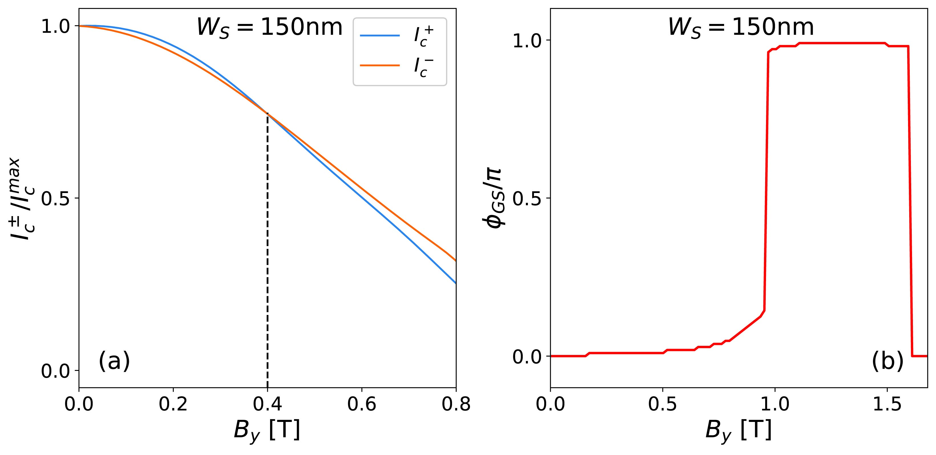
The numerical simulations of the critical currents () and ground-state phase () as functions of the magnetic field are displayed in Fig. S9 for a JJ with nm and . The SOC-induced current asymmetry is not strong enough and no critical current crossing occurs before the transition. The current crossing at which is expected to exhibit a sign change is a consequence of the relative shift of the critical current inflection points, which indicates a jump of the ground-state phase would occur in the absence of currents.
The computed magnetic-field dependence of the critical currents, , and ground-state phase, , are shown in Fig. S10(a) and (b), respectively, for a JJ with narrow S leads (). The results in (a) show a current crossing at T, which is in agreement with the crossing observed in the experimental data at T [see Fig. 4(b) in the main text]. This crossing is responsible for the first zero of the experimentally extracted current difference () at T in Fig. 4(c) of the main text. The ground-state phase in Fig. S10(b) exhibits a transition at a higher field, T. This suggests that the first sign-change of observed in the experimental data at T is not related to a transition. The sign-change induced by the transition is predicted to occur at higher fields and can arguably be observed in the experimental data.