Automorphism Ensemble Polar Code
Decoders for 6G URLLC
††thanks:
The authors acknowledge the financial support by the Federal Ministry of
Education and Research of Germany in the project “Open6GHub” (grant
number: 16KISK019 and 16KISK004).
Abstract
The URLLC scenario in the upcoming 6G standard requires low latency and ultra reliable transmission, i.e., error correction towards ML performance. Achieving near-ML performance is very challenging especially for short block lengths. Polar codes are a promising candidate and already part of the 5G standard. The Successive Cancellation List (SCL) decoding algorithm provides very good error correction performance but at the cost of high computational decoding complexity resulting in large latency and low area and energy efficiency. Recently, Automorphism Ensemble Decoding (AED) gained a lot of attention to improve the error correction capability. In contrast to SCL, AED performs several low-complexity (e.g., SC) decoding in parallel. However, it is an open question whether AED can compete with sophisticated SCL decoders, especially from an implementation perspective in state of the art silicon technologies. In this paper we present an elaborated AED architecture that uses an advanced path metric based candidate selection to reduce the implementation complexity and compare it to state of the art SCL decoders in a 12nm FinFET technology. Our AED implementation outperform state of the art SCL decoders by up to 4.4x in latency, 8.9x in area efficiency and 4.6x in energy efficiency, while providing the same or even better error correction performance.
Index Terms:
Polar Code, Automorphism, Ensemble Decoding, Path Metric, ASIC, 12 nm, ImplementationI Introduction
The Ultra-Reliable Low Latency Communications (URLLC) scenario will be one of the key enablers for 6G. Compared to 5G, it requires lower latency and particular improved error correction [1] towards Maximum Likelihood (ML) performance. Short block lengths enable low latency, but typically at the cost of degraded error correction capability [2]. Hence, one of the key challenges is to find codes, decoding algorithms and efficient decoder architectures that enable low latency, high energy efficiency and, at the same time, error correction performance towards ML performance.
Polar codes are promising candidates for this application. They are the first class of error correction codes proven to achieve the channel capacity for Binary Symmetric Memoryless Channels (BSMCs) [3] and have been adopted for the control channel in the enhanced mobile broadband (eMBB) use case of 5G. Polar codes can be decoded with the Successive Cancellation (SC) algorithm that is a low-complexity decoding algorithm, but suffers on error correction performance, especially for short block lengths. Hence, more sophisticated decoding algorithms were developed. The Successive Cancellation List (SCL) decoding algorithm [4] considers several decoding paths in parallel and selects the best one according to a path metric. With a sufficient large list size , SCL approaches ML performance, but at the cost of a very high computational complexity.
Recently, the GRAND [5] algorithms got a lot of attention. In contrast to the algorithms mentioned above, GRAND is a universal decoding algorithm for any code. The basic idea is to guess noise patterns to find the correct code word. GRAND, in principle, can achieve ML performance if the number of guesses is large enough. But since the number of guesses is unknown in advance, latency and throughput can vary largely between worst case and average. [6] limits this variance, but at the cost of a decreased error correction performance. Moreover, it was shown that the GRAND algorithm and its derivatives are only practical for high Signal-to-Noise-Ratio (SNR) regions and high code rates.
Automorphism Ensemble Decoding (AED) is another new decoding approach that was recently published and can be applied to any code that has automorphisms. The automorphisms are used to permute code words. The different code words can then be decoded in parallel by low-complexity decoding algorithms. While there exist many automorphisms for Reed-Muller (RM) codes [7], it is challenging to find useful automorphisms for polar codes. Recently [8] have shown that automorphisms can also be found for polar codes and that the error-correction performance can be improved significantly.
AED is also very interesting from an implementation point of view. Instead of one complex decoders (e. g., SCL), several low-complexity decoders (e. g., SC) can be used. Each of the low-complexity decoders has a very high implementation efficiency in terms of latency, high throughput, large energy and area efficiency. Since the decoders run in parallel without information exchange, locality is significantly improved. This is very beneficial for a large implementation efficiency and, as a result, area and energy efficiency scale almost linear with the number of ensemble decoder instances , where is defined by the requirement on the error correction performance. It is important to mention that the latency in AED is first order independent of that is unique for advanced decoding.
This work makes the following new contributions:
-
•
A simple data-driven permutation selection method for AED.
-
•
An efficient AED algorithm for very high throughput and low latency that is based on a Fast Simplified SC (SSC) algorithm with a new path metric based candidate selection.
-
•
A detailed comparison of our AED architecture and state-of-the-art SCL decoders with respect to error correction performance and hardware implementation on a FinFET silicon technology. This is, to the best of our knowledge, the first implementation and comparison of AED with traditional decoding algorithms.
The remainder of this paper is structured as follows: We provide the required background of Polar codes and their decoding algorithms in Section II. The concept of AED and a new path metric based candidate selection is provided in Section III. We present a detailed comparison with SCL decoders regarding error correction performance and implementation costs in Section IV and conclude this paper in Section V.
II Background
II-A Polar Codes
Polar codes are linear block codes with code length , which encode information bits. They use the phenomenon of polarization to derive virtual channels. Information is then transmitted over reliable channels listed in the information set , while the remaining (unreliable) channels are set to zero and called frozen bits (frozen set ) [3]. Throughout the paper, we use the following notation: is the code word and its estimation after decoding; represents the vector of received channel Log-Likelihood Ratios (LLRs).
II-B Successive Cancellation Decoding
SC decoding can be described as depth-first tree traversal of the Polar Factor Tree (PFT) [9]. The PFT has stages and leaf nodes at stage , representing frozen bits and information bits. Each node receives a LLR-vector of size to first calculate the elements of the vector
| (1) |
by the hardware-efficient min-sum formulation of the f-function
| (2) |
The resulting vector of size is passed to the left child. With the bit vector received from the left child, the elements of are calculated by the g-function
| (3) |
with
| (4) |
and sent to the right child. With the results of both children and , the partial sum is calculated and send to the parent node. In the leaf nodes, the bit decisions are made. Frozen bits are, per definition, always , information bit nodes return
| (5) |
which is if and otherwise. The decoder output is equal to the output of the root node [9].
II-C Fast-SSC Decoding
The PFT can be pruned to reduce the number of operations to decode one code word. Sub-trees containing only frozen bits don’t have to be traversed, since their decoding result is known to be an all-zero vector in advance. Such subtrees are replaced by Rate-0 (R0) nodes. Similarly, subtrees without any frozen bits can be decoded directly by Hard Decision Decoding (HDD), since no parity information is contained. Therefore, these nodes are called Rate-1 nodes [9].
Further optimizations were proposed by [10], denoted Fast- SSC decoding. If a sub-tree contains only one information bit, it is considered a Repetition (REP) code and replaced by a specialized REP node. All bits with index of a REP node are decoded according to:
| (6) |
In subtrees containing only one frozen bit, this bit always acts as parity bit. Thus, the partial sum of this sub-tree represents a Single Parity-Check (SPC) code. A specialized SPC node performs ML decoding by calculating the parity of the input:
| (7) |
finding the least reliable bit
| (8) |
and setting to satisfy the single parity constraint:
| (9) |
III Automorphism Ensemble Decoding
AED was proposed in [7] as a general method to improve the error-rate performance by running an ensemble of independent SC decoders. Each decoder operates on a permuted version of the received sequence and each decoding result is then unpermuted as
| (10) |
The permutations stem from the automorphism group of the code, which is the set of permutations of the coded bits that map every code word onto a (not necessarily different) code word. Permuted received sequences therefore correspond to different noise realizations which may be easier to decode. Hence, by choosing the most likely candidate from , the probability of finding the correct code word is increased.
III-A Automorphisms and Code Construction
The automorphism group of polar codes contains the Block Lower-Triangular Affine (BLTA) group which is defined as
| (11) |
where is an invertible, block lower triangular binary matrix, an arbitrary binary vector, and are the binary representations of the bit indices before and after permutation, respectively [8]. The block profile of , and thus, the number of automorphisms, is dependent on the choice of the information set . Therefore, for good performance under AED, the polar code design is critical. In [11], the code with minimum information set was found to be particularly well suited for AED, as its BLTA group has block profile .
III-B Automorphism Selection
It was shown in [11] that permutations can be partitioned into equivalence classes. Within each Equivalence Class (EC), a permuted decoding results in the same code word estimate. Hence, at most one permutation from each EC should be used in AED. As the code exhibits 2205 ECs, a subset of ECs has to be selected for use in AED.
Additionally, it is beneficial to have a single list of permutations and smaller ensemble sizes use a subset of this list. As there is no theory yet on how to select a good subset of ECs, we propose a greedy, data-driven method that works as follows:
-
1.
Generate one permutation from each EC.
-
2.
Due to symmetry, select an arbitrary permutation .
-
3.
Collect a batch of noisy code words that cannot be correctly decoded with any of the selected permutations.
-
4.
Decode this batch with the permutations that have not been selected yet and select the one that can correctly decode most of the noisy code words within the batch.
-
5.
Repeat steps 3 to 5 until permutations have been selected.
III-C Conventional Candidate Selection
To select the most probable code word of all decoding results , [7] propose the ML-in-the-list method
| (12) |
that chooses the code word that correlates most with the received LLRs.
III-D Path Metric
A drawback of the ML-in-the-list method is that the received channel LLRs are necessary to perform the final decision. This requires a large buffer in high-throughput decoders that are deeply pipelined. This buffer can account up to 25% of the total decoder area, dependent on . This memory is also a major source of power consumption. Hence, it is important to find techniques to avoid this buffer. We propose a new Path Metric (PM) based candidate selection for AED with SC constituent decoders. This PM technique replaces the ML-in-the-list selection and, thus, increases the locality in the AED implementation. Moreover, it makes the buffer redundant.
A PM is used in SCL decoding to rate the different decoding paths. An efficient LLR-based PM calculation was presented in [12]. In particular, it was shown that a PM calculated as
| (13) |
is a decreasing function with the likelihood of the code word candidates. Therefore, the path with the lowest PM corresponds to the most likely transmitted code word. The terms in (13) have the implementation-friendly approximation
| (14) |
In contrast to SCL decoding, SC decoding does not split the decoding path. For information bits (), is equal to the hard decision on and, therefore, they do not contribute to the PM. Thus, for SC decoding, it is sufficient to update the PM only for frozen bits, where only indicates a transmission error. This leads to the following cost function for the PM in the leaf nodes:
| (15) |
The code word with the smallest PM is then selected as output of AED.
III-E Fast-SSC Path Metric
State-of-the-art high-throughput low-latency decoder architectures are based on the Fast-SSC decoding algorithm [13]. Since Fast-SSC decoding operates on higher stages in the PFT, the LLR values of the frozen leaf nodes are not calculated. Therefore, the PM calculation presented previously is not directly applicable. Thus, we derive PM calculation methods for the specialized nodes analogous to Fast Simplified SCL (SSCL) decoding [14]. The value of is accumulated sequentially, where denotes the index of the leaf node in the pruned PFT and is initialized with .
As discussed above, the SC decoder does not split the decoding path and the PM calculation method is only needed for specialized nodes containing frozen bits, i. e., R0, REP and SPC nodes:
III-E1 Rate-0 nodes
For the R0 node, we follow (15), but execute the calculation directly on the input LLR vector of the node with node size :
| (16) |
III-E2 Repetition nodes
According to (6), the repeated bit decision is based on the sign of the sum of all LLRs related to the REP node. Thus, corrected bits are located at the positions , for which . The PM consequently is calculated by
| (17) |
III-E3 Single Parity-Check nodes
For the SPC node, the decoding includes the correction of the least reliable bit to satisfy the single parity constraint ((7)-(9)). Thus, the PM can be derived as:
| (18) |
Simulations verified that this Fast-SSC PM results in identical error correction performance as the conventional candidate selection based on (12).
III-F Architecture
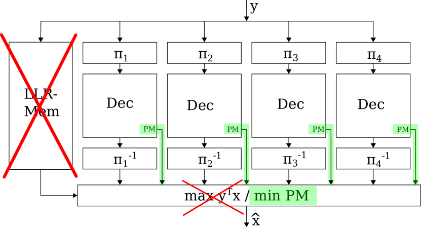
Figure 1 shows an AED architecture with that consists of identical SC decoders. The permutations and map the LLRs and code words related to each SC decoder instance, respectively, according to the automorphisms (Section III-B). This mapping does not require any logic or registers. All decoders work independently and output their decoding results as well as the PM. This PM is calculated in each decoder as described in Section III-E and fed into the selection unit, which then outputs the code word estimate with the lowest PM value. All decoders are generated automatically by a framework as fully unrolled and pipelined architectures.
To illustrate the proposed optimization, Figure 1 also shows the code word selection of the conventional AED architecture with a memory for LLRs and the ML-in-the-list method but crossed out in red, while the novel path metric based selection is highlighted in green.
IV Results
To enable a fair comparison, all decoders (AED and SCL decoders) were optimized for the same throughput, i. e., . We investigated different degrees of parallelism for the AE decoders and list sizes for the SCL decoders. These decoders are denoted AED- and SCL-, respectively. The SCL decoders use the optimizations from [15] and are, to the best of our knowledge, the most efficient SCL decoder implementations for very high throughput.
While this high throughput might not be necessary for the URLLC use case, the investigated unrolled and pipelined architectures are not only highly area and energy efficient, but also offer very low latency, which is one of the core requirements for URLLC. With a reduction in frequency, the throughput could be decreased to reduce power consumption, but at the cost of increased latency.
All designs were synthesized with Design Compiler and placed and routed with IC-Compiler, both from Synopsys in a FinFET technology from Global Foundries under worst case Process, Voltage and Temperature (PVT) conditions (, for timing, for power).
Error correction performance was simulated for an Additive White Gaussian Noise (AWGN) channel and Binary Phase Shift Keying (BPSK) modulation. A minimum of 100 erroneous code words were simulated. To assess the error correction capability of the codes, we also evaluated the ML performance. For this, we simulated two bounds: an upper ML bound and a lower ML bound. If both bounds match, we get ML performance. The upper ML bound was calculated by performing SCL decoding with and counting the cases where a code word is closer to the received channel values than the correct code word. The lower bound is derived in the same way, but additionally the correct code word has to be in the list of candidates.
IV-A Comparison with SCL
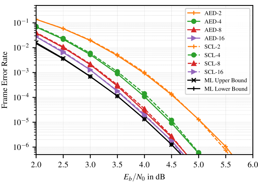
We first compare the error correction performance of AED with SCL decoding (Figure 2) using the same as described in Section III-A. Both decoding algorithms perform very similar over the complete range of / . They both benefit from a high minimum distance. We therefore omitted an additional Cyclic Redundancy Check (CRC) since it doesn’t offer any improvement over the chosen code. For both decoding algorithms approach the ML Bounds.
Table I shows the implementation results. We observe that AED outperforms its SCL counterpart in all presented metrics. With increasing / , the gap between AED and SCL expands, since the AED implementations largely benefit from locality. For , a more than 8.9 better area efficiency, a 4.5 better energy efficiency and a 5.3 shorter latency are observed.
| AED-2 | SCL-2 | AED-4 | SCL-4 | AED-8 | SCL-8 | AED-16 | SCL-16 | |
| Frequency [MHz] | 498 | 476 | 497 | 462 | 498 | 478 | 495 | 403 |
| Throughput [Gbps] | 63.7 | 61.0 | 63.6 | 59.1 | 63.7 | 61.2 | 63.3 | 51.6 |
| Latency [CC] | 11 | 21 | 11 | 27 | 11 | 39 | 11 | 48 |
| Latency [ns] | 22.1 | 44.1 | 22.1 | 58.5 | 22.1 | 81.5 | 22.2 | 119.1 |
| Area [mm2] | 0.045 | 0.064 | 0.087 | 0.154 | 0.170 | 0.450 | 0.338 | 2.464 |
| Area Eff. [Gbps/mm2] | 1407.9 | 956.0 | 733.8 | 385.0 | 375.1 | 136.2 | 187.0 | 20.9 |
| Utilization [%] | 73 | 73 | 73 | 72 | 74 | 74 | 73 | 47 |
| Power Total [W] | 0.07 | 0.09 | 0.15 | 0.22 | 0.32 | 0.61 | 0.64 | 2.38 |
| Energy Eff. [pJ/bit] | 1.16 | 1.48 | 2.32 | 3.73 | 5.01 | 10.02 | 10.12 | 46.21 |
| Power Density [W/mm2] | 1.63 | 1.42 | 1.70 | 1.44 | 1.88 | 1.36 | 1.89 | 0.97 |
IV-B Comparison with 5G
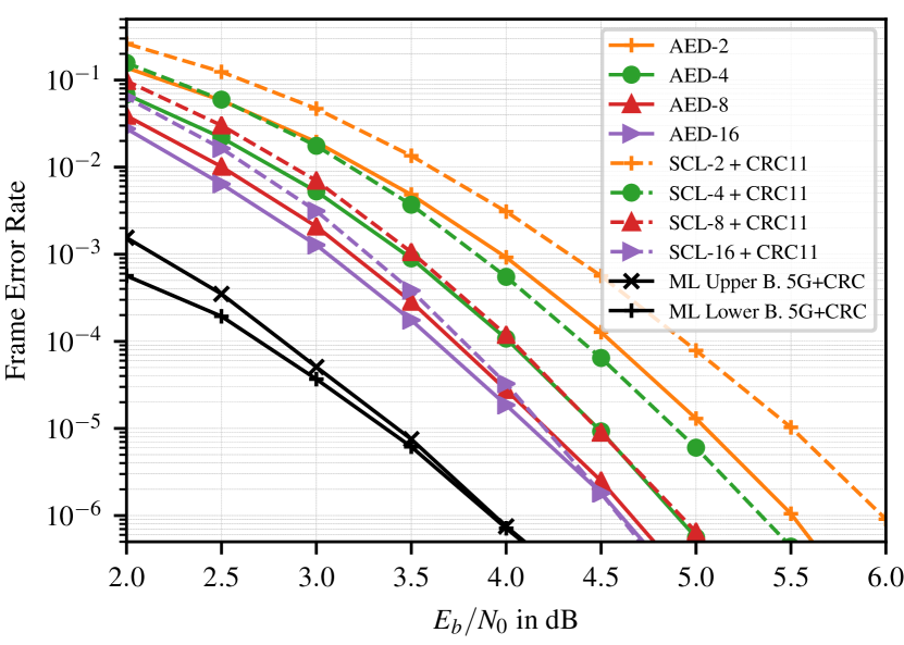
We also compare our implementations with optimized state-of-the-art CRC-aided SCL decoders for a 5G with an CRC length of . As shown in Figure 3, AED outperforms CRC-aided SCL decoding for all / , while for the difference is shrinking for higher SNR. Note that AED-4 provides very similar performance as the CRC-aided SCL-8 and would benefit from additional hardware savings under this error correction requirement. While the ML Bounds for the 5G are lower than for the code, the SCL decoders cannot benefit from that advantage.
Analyzing the implementation costs of the AED and 5G SCL decoders (Table II), implementations show a similar picture as in Section IV-A. However, the decoders for the 5G code show a slightly better area and energy efficiency than for the code without CRC. This is caused by the different code structure leading to different building blocks from the PFT traversal.
It is worth mentioning that the 5G code is optimized for a wide range of code rates and usage scenarios, and not just for error correction performance and implementation efficiency.
| AED-2 | SCL-2 | AED-4 | SCL-4 | AED-8 | SCL-8 | AED-16 | SCL-16 | |
| Frequency [MHz] | 498 | 478 | 497 | 475 | 498 | 478 | 495 | 412 |
| Throughput [Gbps] | 63.7 | 61.2 | 63.6 | 60.8 | 63.7 | 61.1 | 63.3 | 52.8 |
| Latency [CC] | 11 | 21 | 11 | 26 | 11 | 36 | 11 | 47 |
| Latency [ns] | 22.1 | 43.9 | 22.1 | 54.7 | 22.1 | 75.4 | 22.2 | 114.0 |
| Area [mm2] | 0.045 | 0.063 | 0.087 | 0.138 | 0.170 | 0.378 | 0.338 | 1.990 |
| Area Eff. [Gbps/mm2] | 1407.9 | 968.8 | 733.8 | 440.0 | 375.1 | 161.8 | 187.0 | 26.5 |
| Utilization [%] | 73 | 72 | 73 | 73 | 74 | 77 | 73 | 47 |
| Power Total [W] | 0.07 | 0.08 | 0.15 | 0.21 | 0.32 | 0.62 | 0.64 | 1.84 |
| Energy Eff. [pJ/bit] | 1.16 | 1.39 | 2.32 | 3.52 | 5.01 | 10.08 | 10.12 | 34.82 |
| Power Density [W/mm2] | 1.63 | 1.35 | 1.70 | 1.55 | 1.88 | 1.63 | 1.89 | 0.92 |
IV-C Comparison with GRAND
A comparison with the GRAND or Ordered Reliability Bits GRAND (ORBGRAND) algorithm is difficult since there exist not many implementations. In [6] authors present an optimized architecture in a technology for a . Its minimum latency, measured in clock cycles, is still more than the latency of our proposed AE decoder. Further comparison is very difficult since the code differs and the authors provide synthesis results only, while we performed full placement and routing under worst case PVT conditions.
V Conclusion
In this paper, we presented a first AED implementation and comparison with state-of-the-art SCL decoders. We show that AED decoders outperform SCL decoders in latency, area and energy efficiency. We also demonstrate that the error correction performance is comparable with the SCL decoders and, in the case of the 5G code, even exceeds the concatenation with CRC. AED and the proposed architecture is, thus, perfectly suited for the 6G URLLC use case, where low latency and high error correction is required.
References
- [1] W. Saad, M. Bennis, and M. Chen, “A vision of 6G wireless systems: Applications, trends, technologies, and open research problems,” IEEE Network, vol. 34, no. 3, pp. 134–142, 2020.
- [2] C. Yue, V. Miloslavskaya, M. Shirvanimoghaddam, B. Vucetic, and Y. Li, “Efficient decoders for short block length codes in 6G URLLC,” 2022. [Online]. Available: https://arxiv.org/abs/2206.09572
- [3] E. Arıkan, “Channel polarization: A method for constructing capacity-achieving codes for symmetric binary-input memoryless channels,” IEEE Trans. Inf. Theory, vol. 55, no. 7, pp. 3051–3073, 2009.
- [4] I. Tal and A. Vardy, “List decoding of polar codes,” IEEE Trans. Inf. Theory, vol. 61, no. 5, pp. 2213–2226, may 2015.
- [5] K. R. Duffy, J. Li, and M. Médard, “Capacity-achieving decoding by guessing noise,” 2018. [Online]. Available: http://arxiv.org/abs/1802.07010
- [6] C. Condo, “A fixed latency ORBGRAND decoder architecture with LUT-aided error-pattern scheduling,” IEEE Transactions on Circuits and Systems I: Regular Papers, vol. 69, no. 5, pp. 2203–2211, 2022.
- [7] M. Geiselhart, A. Elkelesh, M. Ebada, S. Cammerer, and S. ten Brink, “Automorphism Ensemble Decoding of Reed–Muller Codes,” IEEE Transactions on Communications, vol. 69, no. 10, pp. 6424–6438, 2021.
- [8] ——, “On the automorphism group of polar codes,” in 2021 IEEE International Symposium on Information Theory (ISIT), 2021, pp. 1230–1235.
- [9] A. Alamdar-Yazdi and F. R. Kschischang, “A simplified successive-cancellation decoder for polar codes,” IEEE Commun. Lett., vol. 15, no. 12, pp. 1378–1380, Dec. 2011.
- [10] G. Sarkis, P. Giard, A. Vardy, C. Thibeault, and W. J. Gross, “Fast polar decoders: Algorithm and implementation,” IEEE J. Sel. Areas Commun., vol. 32, no. 5, pp. 946–957, May 2014.
- [11] C. Pillet, V. Bioglio, and I. Land, “Classification of automorphisms for the decoding of polar codes,” in ICC 2022 - IEEE International Conference on Communications, 2022, pp. 110–115.
- [12] A. Balatsoukas-Stimming, M. B. Parizi, and A. Burg, “LLR-based successive cancellation list decoding of polar codes,” IEEE Transactions on Signal Processing, vol. 63, no. 19, pp. 5165–5179, Oct. 2015.
- [13] P. Giard, A. Balatsoukas-Stimming, T. C. Müller, A. Bonetti, C. Thibeault, W. J. Gross, P. Flatresse, and A. Burg, “PolarBear: A 28-nm FD-SOI ASIC for decoding of polar codes,” IEEE Journal on Emerging and Selected Topics in Circuits and Systems, vol. 7, no. 4, pp. 616–629, Dec. 2017.
- [14] S. A. Hashemi, C. Condo, and W. J. Gross, “Fast and flexible successive-cancellation list decoders for polar codes,” IEEE, vol. 65, no. 21, pp. 5756–5769, Nov. 2017.
- [15] L. Johannsen, C. Kestel, O. Griebel, T. Vogt, and N. Wehn, “Partial order-based decoding of rate-1 nodes in fast simplified successive-cancellation list decoders for polar codes,” Electronics, vol. 11, no. 4, 2022. [Online]. Available: https://www.mdpi.com/2079-9292/11/4/560