ARES: Autonomous RIS solution with Energy harvesting and Self-configuration towards 6G
Abstract
Reconfigurable Intelligent Surfaces (RISs) are expected to play a crucial role in reaching the key performance indicators (KPIs) for future 6G networks. Their competitive edge over conventional technologies lies in their ability to control the wireless environment propagation properties at will, thus revolutionizing the traditional communication paradigm that perceives the communication channel as an uncontrollable black box. As RISs transition from research to market, practical deployment issues arise. Major roadblocks for commercially viable RISs are ) the need for a fast and complex control channel to adapt to the ever-changing wireless channel conditions, and ) an extensive grid to supply power to each deployed RIS. In this paper, we question the established RIS practices and propose a novel RIS design combining self-configuration and energy self-sufficiency capabilities. We analyze the feasibility of devising fully-autonomous RISs that can be easily and seamlessly installed throughout the environment, following the new Internet-of-Surfaces (IoS) paradigm, requiring modifications neither to the deployed mobile network nor to the power distribution system. In particular, we introduce ARES, an Autonomous RIS with Energy harvesting and Self-configuration solution. ARES achieves outstanding communication performance while demonstrating the feasibility of energy harvesting (EH) for RISs power supply in future deployments.
Index Terms:
B5G, 6G, RIS, Self-configuration, Energy harvesting, HRIS, IRS, IoS1 Introduction
The ever-increasing need for network performance improvement has led to exploring new ways to push communication transmission efficiency that go beyond the classic communication paradigm. A revolutionary technology capable of providing control over the propagation environment has been recently introduced: metasurfaces with their reflectarray-based variant, namely Reconfigurable Intelligent Surface (RIS), raise the possibility of altering the way waves propagate in the environment in an intelligent, controllable and flexible fashion, opening up the possibility of optimizing it for unprecedented communication performance [1]. While this game-changing technology introduces a bulk of new business opportunities and advanced use-cases for the next generation of wireless networks (B5G or 6G), it involves new challenges to be addressed [2].
The RIS paradigm transforms the propagation environment from an adversary to an optimizable communication ally actively contributing to improving performance, with the sole use of surfaces equipped with low-cost, and low-complexity electronics [3]. However, RISs require an ad-hoc control channel to adapt to the network dynamics. Furthermore, being quasi-passive devices, channel estimation requires complex procedures performed on the entire transmitter-RIS-receiver path, which can hamper their agile deployment [4]. To counter this drawback, the concept of hybrid reconfigurable intelligent surface (HRIS) has been proposed in [5], bringing built-in sensing capabilities to quasi-passive RISs. This kick-started the development of self-configuring RISs as the epitome of a plug-and-play (P&P) RISs integration solution into existing network deployments that eliminates the need for the control channel and operator management, paving the way to the massive and flexible deployment of RISs known as Internet-of-Surfaces (IoS) [6].
As operational RISs draw limited amount of energy [7], they may run on compact batteries, thereby requiring no continuous external power supply but calling for periodic maintenance, which might limit their operational availability. Alternatively, energy harvesting (EH) techniques may be implemented at the RISs to provide them with potentially unlimited energy availability, avoiding the need for servicing for long time periods [8] and leading to a fully autonomous solution in terms of configuration, energy, and maintenance.
Pursuant to the IoS framework, we select HRISs as reference hardware due to their signal reflection, absorption, and sensing capabilities. In [6], we previously analyzed one of the fundamental constraints of a conventional RISs deployment, i.e. the need for a reliable control channel, and introduced MARISA as a novel system design that achieves fully-autonomous and self-configuring RISs deployments. In this paper, we extend [6], going one step beyond and targeting the need for a power supply to devise a fully-autonomous, self-configuring, and energy self-sufficient metasurface solution, namely Autonomous RIS with Energy harvesting and Self-configuration (ARES). ARES takes advantage of the key assets brought in by MARISA, namely the new channel estimation model lato-sensu at the HRIS and the autonomous HRIS configuration methodology based only on the channel state information (CSI) available at the HRIS, and establishes the following main contributions: ) the design of a fully integrated radio frequency (RF) EH technology to empower off-the-grid operations, ) an accurate model of the battery charging and discharging processes based on an irreducible Markov chain (MC), ) a battery dimensioning strategy that guarantees the availability of the HRIS for the desired time period. ARES is shown to provide near-optimal performance when compared to the full-CSI-aware and power-grid-enabled approaches while facilitating energy self-sufficient IoS deployments.
The remainder of this paper is as follows. Section 3 provides preliminary information about our HRIS-based design pointing out the major roadblocks to a fully-autonomous IoS deployment. Section 4 provides an overall view of the building blocks of our solution. Section 5 introduces the system model and the optimization problem for an HRIS without RF chains and a dedicated control channel. Besides, it presents a novel analysis for energy management at the HRIS leveraging on a bespoke Markov-chain model to represent the battery charge and discharge processes. Section 6 unlocks the HRIS self-configuration and energy self-sufficiency by tackling the aforementioned problem via codebook-based optimization, which is complemented by the assessment of the HRIS hardware-related power consumption. Section 7 shows ARES performance against state-of-the-art (SoA) and heuristic solutions whereas Section 2 includes a survey of the related literature. Finally, Section 8 concludes the paper.
Notation. We denote matrices and vectors in bold text while each of their element is indicated in roman with a subscript. and stand for vector or matrix transposition and Hermitian transposition, respectively. The L-norm of a vector is denoted by while indicates the trace of a matrix. Also, denotes the inner product between vectors, and denotes the Hadamard product between two matrices.
2 Related Work
In the last few years, RISs have drawn considerable interest from the scientific community due to their ability to turn uncontrollable propagation channels into controlled variables that can be optimized [9, 10]. A preliminary analysis of the achievable performance of an RIS is given in [11]. In particular, the authors formulate a joint optimization problem for optimizing the active beamforming (at the multi-antenna base station (BS)) and the passive beamforming configuration (at the RIS), and they demonstrate that RIS-based multiple-input multiple-output (MIMO) systems can achieve rate performance similar to legacy massive MIMO systems with fewer active antenna elements. The ideal case study with continuous phase shifts at the RIS is generalized to the case with discrete phase shifts in [12]. The authors prove the squared power gain with the number of reflecting elements even in the presence of phase quantization, but a power loss that depends on the number of phase-shift levels is observed [13]. In [14], the authors propose a practical algorithm to maximize the system sum mean squared error while jointly optimizing the transmit beamforming at MIMO BSs and the RIS configuration. Other papers have recently considered the possibility of optimizing the RISs based on statistical CSI in order to relax the associated feedback overhead. A two-timescale transmission protocol is considered in [15] to maximize the achievable average sum-rate for an RIS-aided multiuser system under a general correlated Rician channel model, whereas [16] and [17] maximize the network sum-rate by means of the statistical characterization of the locations of the users, which does not require frequent updates of the RIS reconfiguration. These solutions, however, rely on the presence of a control channel. A detailed analysis of an RIS-assisted multi-stream MIMO system is described in [18], where the authors formulate a joint optimization problem of the covariance matrix of the transmitted signal and the RIS phase shifts. An effective solution is obtained, which offers similar performance to SoA schemes but with limited computational complexity. The approach is generalized in [19] to discrete-valued constellation symbols. A comprehensive tutorial on RISs focused on optimization is available in [20].
As for the RISs design, several prototypical architectures are available in the literature. The majority of works consist of a positive-intrinsic-negative (PIN) diode-based design, achieving different phase shift quantization levels. Early works like [21] and [22] propose RIS hardware designs with 1-bit phase shift resolution, operating at 28 GHz and 5.8 GHz, respectively. Similar approaches offer more quantization bits at the expense of higher circuital complexity, such as [23] producing 4 possible phase shifts with 5 PIN diodes per element and [24] allowing for 8 phase shifts by means of 3 PIN diodes. A multi-frequency design is disclosed in [25], paving the way for the development of RISs able to dynamically operate across different carrier frequencies by using frequency-tunable antennas as elements. In addition to PIN diodes, varactor diodes may be employed to control the phase response of each RIS element, enabling continuous tuning of the applied phase shifts [26]. As a reference, [27] proposes to use 4 varactors per element in order to ensure a symmetric radiation pattern in the 5.15-5.75 GHz frequency range. Alternative designs make use of RF-switches [28], thanks to the lower associated production cost. For instance, the authors of [29] design and build a two-dimensional surface consisting of 80 rectangular boards, each containing antennas on custom-printed circuit boards. Specifically, the RF-switches determine whether the signal propagates through the surface or is reflected. On these lines, [30] proposes a 5 GHz RIS design with 2-bit phase resolution by leveraging on transmission lines to generate different phase shifts at each RIS element whereas the RF-switches are used to route the signals on the optimal line (according to the RIS configuration). Besides, the work in [7] builds upon the transmission-line method to design a 3-bit resolution RIS and introduces the possibility of setting each of the RIS elements (separately) to fully dissipate the impinging RF power, i.e., effectively turning off some of the RIS elements, and virtually changing the overall shape of the array.
None of the above-mentioned works deal with self-configuring RIS-empowered networks without relying on a control channel. Moreover, although [7] hints to an absorption mode for RIS elements, such energy is only dissipated over a matched load and is not used to power the device and enable its energy self-sufficiency, thereby underlining the contributions and novelty of the present paper.
3 Plug & Play HRIS: Key Characteristics
In this section, we introduce the key concept of HRIS and provide a brief overview of the proposed bespoke hardware design. Then, we analyze the challenges that need to be overcome to enable self-configuration and self-sufficiency capabilities for the HRIS.
3.1 Hardware design
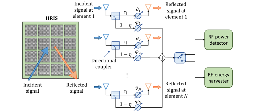
Hybrid metasurfaces. We consider an HRIS [5] comprising an array of hybrid meta-atoms, which are able to simultaneously reflect and absorb (i.e., sense the power of) incident signals. In the considered architecture, each metasurface element is coupled with a sampling waveguide that propagates the absorbed (i.e., sensed) power of the incident electromagnetic (EM) waves towards some downstream RF hardware for enabling digital signal processing (DSP). To reduce the complexity and cost of the required hardware with respect to conventional HRIS and enable EH, we propose P&P HRISs that are not equipped with fully-fledged RF chains but only with an RF power detector and an RF energy harvester. As shown in Fig. 1, the signals absorbed by each metasurface element are summed together by means of RF combiners, which may be easily implemented as lumped components throughout the metasurface RF circuit [31]. The resulting signal is fed into an RF switch, which routes it to either the above-mentioned power detector or the energy harvester. The former converts the RF power into a measurable direct current (DC) or a low frequency (LF) signal, and is made by, e.g., a thermistor or a diode detector, [32, 33]. The latter extracts energy from the EM fields in the form of DC voltage by means of a rectifier or a voltage multiplier that boosts the output DC by stacking multiple rectifiers, such as in the Cockcroft–Walton or Dickson configurations [34]. By leveraging on such components, we respectively enable HRISs self-configuration and energy self-sufficiency111 In some implementation, the RF power detector and the RF energy harvester might be fully integrated [35]. However, the electronic circuit design of such device is out of the scope of this paper..
Phase shifters banks design. In the considered hardware architecture, the reflected and absorbed signals are subject to a phase shift applied by the metasurface elements. In particular, each signal is fed to its corresponding phase shifter bank, which is optimized independently of the other, allowing us to simultaneously control the signal reflection and power absorption properties of the HRIS. We will discuss the effects of dependent phase shifts optimization, i.e., the condition in which the same phase shifter bank operates on both the reflected and absorbed signals, in Section 6.1. Here, we underline that independent phase shifter banks can be obtained at once by introducing one additional phase shifter at each meta-atom even starting from a dependent phase shifter banks design, though at the expense of higher circuit complexity.
3.2 The Road Towards the IoS: Self-Configuring and Self-Sufficient RISs
Managed RISs deployment. Conventional SoA RISs deployments rely on a control channel between the RISs and a centralized controller222RISs are conventionally controlled by a centralized entity (i.e., an orchestration layer) or by the BS itself., which serves a twofold purpose: ) sharing the CSI estimated at the BS and the RISs, ) enabling the joint optimization of the BS precoding matrix and the phase shifts at the RIS elements, in order to avoid losses due to the out-of-phase reception of uplink (UL) signals at the BS or downlink (DL) signals at the user equipments (UEs). Indeed, if both the direct and reflected (through one or multiple RISs) propagation links between the BS and a user equipment (UE) are available, the transmission delays experienced by the transmit signals over the two paths may be substantially different, thereby requiring the RIS to be configured for compensating them. Such configuration is feasible only if the centralized control entity has access to the CSI of the direct and reflected propagation channels, as well as having full control on the RIS configuration. Furthermore, although RISs operation requires little power (mainly for the RIS controller and the phase shifting circuitry), currently envisioned RISs deployments run on an extensive electrical system, which powers each individual RIS to enable their wave manipulation functionality [36]. Therefore, managed RISs deployments ) raise doubts as to their cost-effectiveness when compared to BSs deployments without RISs, thus discouraging their full-scale adoption, ) bring along stringent physical constraints (i.e., need for control channel and electrical power) to network operators willing to be early adopters of such technology [37].
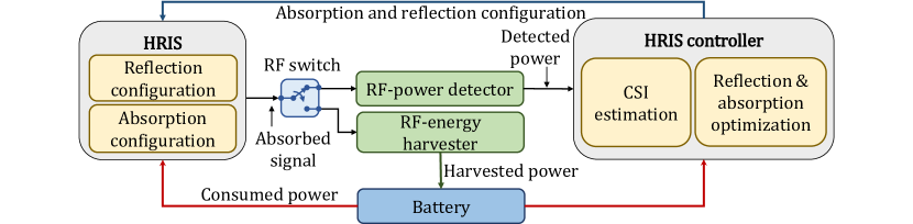
Autonomous HRISs deployment. Avoiding the need for an external management-and-control entity and an extensive power grid has major positive implications for the design and deployment of RIS-aided wireless networks. In the IoS landscape it is envisioned that novel RISs devices will be completely autonomous in terms of configuration and power supply, requiring neither a dedicated control channel nor an electrical power source, thereby maximizing the agility and flexibility of their deployment while keeping the installation, configuration and maintenance costs minimal. While typical implementations of RISs cannot operate without an external control channel, the self-configuring HRIS we recently proposed in [6] does not rely on the existence of a remote control channel. Instead, it is built upon the optimization and configuration of the HRIS uniquely based on local estimates of the CSI at the HRIS itself. In this work, we extend our previous work in [6] and bring the self-configuring HRIS to the next level, allowing the HRIS to detach from a continuous power supply by integrating the capability of harvesting the absorbed EM energy, which is stored in a properly-sized rechargeable battery to support off-the-grid operations, as depicted in Fig. 2. Hence, we can achieve autonomy both from the control and the energy standpoints.
4 ARES overview
We depict the main building blocks of ARES in Fig. 2 and remark that the reference HRIS design has two branches, namely reflection and absorption. As the reflection branch is fully passive like in any typical RIS, here we highlight the path of the absorbed signal to the HRIS controller, which outputs the HRIS reflection and absorption configuration, as well as annotating the energy transfer to and from the service battery. To fully comprehend ARES operation, we first introduce the reference communication frame. This is important to ensure that the autonomous operation of the HRISs is compliant with the standard by which BS and UEs communicate.
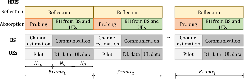
ARES reference communication frame. Without loss of generality, we assume that all devices use TDD duplexing, specifically with the frame structure shown in Fig. 3. As described in Section 3.1, the two HRIS branches enable independent signal routes with different phase shift banks. This is implemented in the frame structure: while the HRIS continuously reflects the impinging signals through the reflection branch, the absorption branch is involved in two fundamental operations, i.e. probing and EH, and leverages on power-based indirect beamforming, which is described below. At the beginning of each frame, the UEs transmit pilot signals over slots while the BS performs channel estimation to acquire end-to-end CSI 333This frame structure follows massive-MIMO procedures [38].. At the same time, such pilots are sensed by the HRIS through probing to obtain a local estimate of the CSI (see Section 5.2). It is worth highlighting that the end-to-end CSI would be affected by the additional high-gain paths provided by the HRIS through the reflection branch. Hence, to minimize the channel estimation errors at the BS, we assume that the CSI acquired at the HRIS within a given communication frame is used to optimize the HRIS reflection configuration in the subsequent one. Once the channel estimation phase is complete, the BS optimizes the precoder and initiates the communication consisting of and slots dedicated to the UL and the DL direction, respectively. Concurrently, the HRIS enables the energy harvester and selects the most suitable absorption configuration to harvest EM energy from the BS (DL) and the UEs (UL).
Power-based indirect beamforming. Both consumers of the absorbed signal in Figs. 1 and 2, i.e. the power detector and the energy harvester, require beamforming to enable channel estimation and EH, respectively. Let us begin by identifying the challenges to be overcome when establishing autonomous HRIS operations—probing and EH—with only one RF power detector, which can exclusively measure the sum-power of all the incident signals at every HRIS meta-atom. Most available angle of arrival (AoA) estimation techniques necessitate the signal samples at each receive antenna. Conversely, we make the most out of our proposed hardware design and perform an indirect estimation of the AoA, by optimizing the phase shifts applied to the absorbed (sensed) signals at every meta-atom so as to maximize the power sensed by the detector. As adjusting the phase shifts applied by the meta-atoms is equivalent to realizing a virtual (passive) beamformer towards specified AoAs of the incident signals with respect to the HRIS surface, we can take advantage of the power sensing capability of the HRISs for estimating the BS-HRIS and HRIS-UE channels with very little local information, and accordingly configure the reflection and absorption branches to support communication and EH.
HRIS self-configuration. The optimal configuration of the HRIS is discussed in Section 5.2. Here, we anticipate that any algorithmic solutions for optimizing the absorption and reflection properties of the HRIS require the estimation of the CSI of the BS-HRIS and HRIS-UE channels. This results in a chicken-egg problem that needs to be tackled. To this end, in Section 6, we devise an online optimization approach that relies upon a finite set of HRIS configurations, namely a codebook, that can be iteratively tested for probing a finite set of predefined AoAs.
HRIS self-sufficiency. The cheapest and most straightforward approach to enable HRIS energy self-sufficiency without deploying an extensive electrical network is to endow each HRIS with a dedicated battery, e.g. lithium-ion (Li-ion) or nickel metal hydride (NiMH). However, battery-operated HRISs call for regular maintenance, generating recurrent costs and additional complexity at radio access network (RAN) planning stage. Conversely, by introducing the ability to harvest the absorbed RF energy, our proposed solution opens up the possibility of a self-sufficient HRIS design that can sustain its operation by replenishing the service battery on the go. In Section 5.3, we discuss in detail its feasibility in terms of required battery capacity and link its realization to a realistic evaluation of the HRIS hardware consumption in Section 6.2.
5 Model Design
In this section, we introduce the reference analytical model for the considered wireless HRIS-aided network scenario. We start by stating the HRIS configuration problem accounting for the practical limitations of such hardware platform.
5.1 Communication System Model
We consider a scenario in which a BS equipped with antennas serves single-antenna UEs with the aid of an HRIS. We model the BS as a uniform linear array (ULA), and the HRIS as a planar linear array (PLA) equipped with meta-atoms, where and denote the number of elements along the and axis, respectively. We assume that the inter-distance of the BS and HRIS array elements is , where denotes the carrier wavelength, is the corresponding carrier frequency and is the speed of light. The joint reflection and absorption capabilities of the HRIS are realized through directional couplers444A practical implementation of this architecture can be found in [5]. whose operation is determined by the parameter , which is the fraction of the received power that is reflected for communication, while is the amount of absorbed power to be measured at the power detector or harvested at the energy harvester.
We denote by , and the locations of the BS center, the HRIS center and the -th UE, respectively. Focusing on the DL, the BS transmits data to the -th UE over a direct line-of-sight (LoS) link and a reflected link through the HRIS. Such path can be decomposed into the LoS channel through which the HRIS reflects the impinging signal towards the UE, and the LoS channel between the BS and the HRIS.
The array response vectors at the BS and at the HRIS towards the generic location are denoted by and , respectively. Their elements are defined as , and , where and are the wave vectors, which are defined as
| (1) |
with and denoting the coordinates of the -th BS antenna element and of the -th HRIS meta-atom, respectively.
The overall gain of a generic communication path between two given locations , is defined as , where is the channel gain at a reference distance and is the pathloss exponent. Hence, the BS-HRIS and the HRIS- channels are
| (2) |
| (3) |
While, the direct BS- channel is
| (4) |
Thus, the received signal at the -th UE is
| (5) |
where , with and , being the phase shifts and the gains introduced by the HRIS, is the transmit precoding matrix whose -th column is the transmit precoder of , is the transmit symbol vector with , and is the noise term whose distribution is . Moreover, we assume that and can be independently optimized. Lastly, we underline that the phase shifters banks in Fig. 1 can apply different configurations to the incident signal on the reflection and absorption branches, respectively. This assumption allows decoupling the two HRIS operations maximizing the harvested energy without affecting the communication task.
5.2 HRIS Optimization
In this section, we focus on how an HRIS can be endowed with self-configuring capabilities, and, in particular, how the absence of a dedicated control channel results in the need for the HRIS of locally estimating the channels towards the BS and the UE, in order to establish and maintain a high-quality reflected path. To this end, we commence by formulating the optimization problem without imposing the absence of the control channel, and we then elaborate on the difficulty of solving the obtained problem by relying only on local CSI at the RIS. The signal-to-interference-plus-noise ratio (SINR) at the -th UE can be written as
| (6) |
where is assumed to be given during the optimization of the configuration of the HRIS. More precisely, is optimized by the BS after the channel estimation phase. The disjoint optimization of and the RIS configuration facilitates the design and deployment of a control channel-free HRIS. The optimization of is elaborated in further text. We aim at finding the optimal HRIS configuration that maximizes the network sum-rate, which is directly related to the SINR at every UE. More precisely, the network sum-rate is defined as .
A feasible strategy to maximize the sum-rate is to optimize the HRIS configuration so that the intensity of in (6) is maximized, i.e., the end-to-end RIS-assisted channel gain of each user is enhanced, which is approximately equivalent to maximizing the as demonstrated in [6]. Upon completion of this optimization, the BS can optimize the precoding matrix . Indeed, even though the BS cannot control the HRIS configuration due to the absence of a control channel, it can always estimate the direct channel towards each UE and the equivalent RIS-assisted link.
Channel estimation and HRIS configuration. Let us now focus on the optimization of the HRIS configuration, by taking into account that it is equipped with a single RF power detector. To this end, we derive a closed-form expression for the HRIS configuration that maximizes the reflected power. We assume that a training phase exists, during which the BS and each UE transmit a pilot symbol in order to realize the initial beam alignment procedure555This standard procedure is essential before data transmission in, e.g., millimeter-wave networks for initial device discovery and channel estimation [39].. Without loss of generality, we assume a certain degree of synchronization, i.e., the BS and the UEs transmit at different times, but all UEs transmit simultaneously. We will relax this latter assumption in Section 6.1.
For ease of presentation, we define and representing the HRIS configuration in the reflection and the absorption branch, respectively, as
| (7) | ||||
with . The signals at the output of the RF combiner on the absorption branch, which are obtained from the pilot signals transmitted by the BS and the UEs, are formulated as
| (8) | ||||
where we assume that the BS and the UEs emit the same amount of power and is the additive noise term. Let be the optimal BS precoder for the BS-HRIS link. We will see shortly that the knowledge of is not explicitly needed to optimize the HRIS configuration. Also, we define . Since the UE-HRIS channel corresponds to the UL, to use it in the DL, we assume that the channel reciprocity holds.
Therefore, the power and available for the power detector or the energy harvester downstream of the RF combining circuitry can be formulated as the expectation and , which is
| (9) | ||||
| (10) |
when absorbed from the pilot signals emitted by the BS and the UEs, respectively. In order to be self-configuring, an HRIS needs to infer the channels and only based on and in (10), respectively. This is equivalent to finding the configuration of the HRIS that maximizes and , which in turn corresponds to estimating the directions of incidence of the signals on the HRIS. As a result, we formulate the following optimization problem, whose solution is the HRIS configuration that maximizes
| (11) | ||||
| s.t. |
where is the th element of . The objective function in (11) can be recast as
| (12) |
where is the projection of the BS precoding vector onto the BS-HRIS direction. Hence, the optimal HRIS configuration for maximizing the absorbed power from the BS is with
| (13) |
Analogously, the optimal HRIS configuration that maximizes is with
| (14) |
From (13) and (14), we evince, as anticipated, that the optimal HRIS configuration that maximizes the sensed power (i.e., the HRIS absorption configuration) depends only on the HRIS array response vectors towards the BS and UE directions, but it is independent of the (optimal) BS precoding.
Based on and , we are now in the position of proposing a distributed approach for optimizing the HRIS configuration in the reflection branch (i.e., the HRIS reflection configuration). In particular, we formulate the following optimization problem.
Problem 1 (Multi-UE SINR-based HRIS configuration)
| (15) | ||||
| s.t. |
Problem 1 is independent of the direct channels between the BS and the UEs, as well as of the BS precoder : these are fundamental requirements due to the lack of control channel. Notably, the objective function in (15) is a lower bound for the sum of the powers of the signals transmitted by the UEs independently, i.e. , which are reflected by the HRIS. This allows us to reformulate the objective function in (15) as
| (16) |
where is the equivalent channel that accounts for the overall effect of the aggregate UE-HRIS channels from the HRIS standpoint, and is the reflected path between the BS and the HRIS for a given precoder at the BS.
Therefore, the HRIS optimal configuration solution of Problem 1 is
| (17) |
which proves that the HRIS configuration in the absence of a control channel can be inferred solely from and .
5.3 Energy Management Model
In the following, we extend the above-mentioned HRIS self-configuration capabilities and propose our energy self-sufficient design. It is worth highlighting that the HRIS does not perform self-configuration and energy harvesting concurrently. In particular, as described in Section 5.2, the HRIS self-configuration requires measuring the sensed power of pilot signals transmitted by the BS and the UEs during the probing phase. On the other hand, once configured, the HRIS harvests energy from the RF signal emitted by the BS and the UEs while communicating, i.e. from transmissions over the DL BS-HRIS and the UL UEs-HRIS links666 We assume the DL and UL wireless channels to be reciprocal.. When performing EH, the energy harvester converts the absorbed RF power to electrical power, which we use to operate the HRIS without the need for an external power supply. Moving forward, we characterize both the energy collected and consumed by the HRIS, and identify the fundamental design and operational choices behind the implementation of an EH-aided self-sufficient HRIS.
Energy harvesting and consumption. Given the configuration in (7) of the HRIS absorption branch (i.e., the HRIS absorption configuration) and the input RF power and in (10) to the energy harvester, the harvested power from the BS-HRIS and UEs-HRIS transmissions can be respectively expressed as
| (18) |
with denoting a non-linear function representing the input-output (I/O) characteristic of the harvester, namely
| (19) |
where , , and are constants fitting the I/O response of the harvester [40]. We consider the DL and UL UEs-BS transmissions to be scheduled according to a typical TDD frame consisting of DL and UL transmission time slots, as sketched in Fig. 3. Hence, the overall harvested power is obtained as
| (20) |
where we introduce the factor to model that ) each time slot corresponds to a transmission opportunity for the BS and the UEs, which is taken according to the level of traffic to be transmitted by each device; ) the EH is performed alternatively to the self-configuration function, thus for a fraction of the total active time, as to keep the HRIS configuration up-to-date while collecting enough RF power to operate.
We now analyze the HRIS power consumption. While from the communication standpoint, the HRIS is a passive device, our design requires (minimal) electrical power to operate its active components, namely the power detector when measuring the absorbed RF power and the meta-atoms to hold the desired phase shifts configuration. As the power consumption depends on the specific HRIS hardware, it can be modelled as
| (21) |
where is a custom function taking into account the instantaneous HRIS reflection and absorption configuration for a specific hardware design, which is tailored to a realistic HRIS implementation in Section 6.2. Let us consider the alternation between EH and power detection (i.e., self-configuration) being periodic every second, i.e. reconfiguration period. The average harvested and consumed energy in each reconfiguration period can be written as
| (22) |

Markov-chain-based energy storage model. The derivation of the conditions for energy self-sufficiency requires a model for the HRIS battery. Specifically, we represent the energy storage in the HRIS battery as a homogeneous Markov process777 MC models for energy storage have been empirically proven in the literature, see e.g. [41]., in which the next battery state-of-charge (SoC) depends only on the current one, satisfying the so-called Markov memorylessness property [42]. Let us consider the MC model in Fig. 4, whose discrete states correspond to the possible HRIS battery states of charge, spanning from state , i.e., fully discharged, to state , i.e., fully charged. Without loss of generality, we consider the difference in energy between two adjacent states to be constant. Thus, we can define the battery capacity as
| (23) |
under the assumption of linear charge and discharge processes. We indicate the transition probability matrix (or stochastic matrix) as , wherein each element denotes the probability of moving from state to state . The amount of energy stored in the battery in each time unit is not constant, thereby leading to possible multiple state changes. In fact, we have no prior knowledge on the amount of harvested energy from the BS and UEs during their communication, as it is tightly coupled to several external factors as per (20). Therefore, for ease of derivation, we consider the net stored energy per unit of time to be randomly distributed with cumulative distribution function (CDF) . Besides, we assume the associated stochastic process to be stationary as to guarantee that its unconditional probability distribution remains constant when shifted in time (i.e., for every unit of time).
The transition probabilities can be written as
| (24) | ||||
| (25) | ||||
| (26) |
where we reflect that a net stored energy is required to move up from the current state, while leads to a transition to a previous state. For instance, transitioning from the current SoC to the following one demands that , while a two-state transition upwards requires that . Furthermore, additional depletion of charge from the battery in state or increase of charge in state do not change the current MC state, i.e. the extremes of the SoC intervals are saturation points due to the underlying physical implementation of the battery management circuitry.
As mentioned above, is a continuous random variable (RV), which allows deriving an equivalent and more compact formulation of the transition probabilities by means of its CDF , namely . Hence, the transition probabilities can be re-written as
| (27) | ||||
| (28) | ||||
| (29) |
In the steady state, the limiting probabilities are obtained as , where is the stationary distribution indicating the expected probability of ending in each of the states upon the convergence of the MC. It is worth highlighting that we prevent state from being an absorbing state for the MC, namely a state that once entered cannot be left, by assuming that the HRIS with a low battery SoC defaults to an idle configuration that does not consume power while enabling power absorption, just at a lower efficiency. In particular, to achieve negligible power consumption, we deactivate all phase shifters when the battery SoC falls below a minimum guard threshold , thereby making the HRIS only capable of harvesting power from signals incoming from within the solid angle enhanced by the idle beamforming configuration. This results in a loss of efficiency, which under the assumption of uniformly distributed UEs in the service area, returns a fraction of the harvested power, namely , where , with , denoting the beamwidth on the horizontal and vertical axis of the corresponding beamformer. Following [43], we consider , , whereas is the HRIS element-spacing wavelength ratio.
Given the above formulation, we are in the position to analyze the energy self-sufficiency condition for the HRIS, i.e., the condition in which the SoC is greater than . We define as the probability of loss of charge (LoC), namely the probability of the MC not being able to meet a negative net stored energy without falling below given its current SoC. In other words,
| (30) |
where we consider all the possible mutually exclusive events leading to a LoC, and where we denote as the state of the MC corresponding to the minimum SoC guard threshold. As per (30), depends on the stationary probabilities and the transition probability matrix , which in turn are affected by the number of states , the energy difference between subsequent states , and the statistics of the net stored energy . Therefore, for a given distribution, we perform a linear search on and a set of feasible ’s and derive and to approach the design . The corresponding minimal battery capacity is then given by (23).
6 Codebook-Based Optimization of HRISs
Problem 1 provides us with a mathematical model for optimizing the HRIS configuration based on information gathered on the absorption branch. From a practical standpoint, however, the optimal solution in (17) depends on the array response vectors from the HRIS towards the BS and the UEs. To implement the obtained solution, the array response vectors, i.e., the BS-RIS and RIS-UEs AoAs, need to be estimated, but this is not possible at the HRIS due to the absence of RF chains and of a control channel. In this section, we propose a codebook-based approach for estimating the necessary AoAs and then computing , and in a distributed manner and locally at the HRIS, i.e., our proposed ARES.
6.1 ARES
ARES optimizes the HRISs based on an appropriately designed codebook [6], which allows for the estimation of the BS-RIS and RIS-UEs AoAs in a distributed manner. The use of codebooks is a known approach in RIS-assisted communications, e.g., [12, 44], and it is usually implemented by assuming that the electronic circuits of the RIS can realize a finite number of phase responses (e.g., through PIN diodes [45]). Therefore, our proposed ARES is compatible with conventional implementations of RISs, but it does not need a control channel.
Let us consider a codebook , whose codewords are unit-norm beamforming vectors that correspond to a discrete set of possible phase shift matrices . In particular, each codeword is constituted by discrete-valued entries that mimic a sort of phase quantization. The discrete values of the codewords are assumed to belong to the following set
| (31) |
where is the possible number of discrete values.
In ARES, the HRIS operates in a TDD fashion, as introduced earlier in Section. 4, which includes probing and EH (absorption branch), and reflection (reflection branch). During probing, the HRIS estimates the AoAs that correspond to the BS and to the UEs. Upon probing completion, the HRIS has gathered enough information to derive and set the reflection and absorption configuration as to assists the transmission of data between the BS and the UEs while harvesting enough EM energy to sustain its own operation.
Without loss of generality, we assume that each codeword of the codebook is, to a certain extent, spatially directive, i.e., the resulting HRIS configuration maximizes the absorbed power only in correspondence of a (narrow) solid angle. This is relatively simple to realize by enforcing, e.g., some constraints on the design of the condewords in terms of half-power beamwidth of the corresponding radiation pattern of the HRIS. Therefore, by iteratively sweeping across all the codewords , the HRIS can scan, with a given spatial resolution, the three dimensional (3D) space and can detect network devices (the BS and the UEs) by using pilot signals emitted only by those devices. During this probing phase, the HRIS collects a set of power measurements, or equivalently a power profile, where each element is the power level sensed (measured) by the HRIS when using the codeword . As a result, the array response vectors in or can be estimated from . In practice, this boils down to detecting the peaks in and identifying the corresponding angular directions. By construction, in fact, the HRIS detects a power peak only if there is at least one transmitter in the direction synthesized by the HRIS beampattern, i.e. the considered codeword. The finer the angular selectivity of the HRIS, the longer the probing phase. Therefore a suitable compromise needs to be considered. In particular, we assume that is a power peak in if it is greater than a given threshold . Let be the set of indexes corresponding to the power peaks. Then, depending on which devices transmit their pilot signals, and in (17) can be estimated as
| (32) |
where is a weight parameter that allows performing a hard () or a soft () combining of the power peaks in based on the actual measured power . Therefore, probing directly returns the HRIS absorption configurations and to perform EH from the BS and the UEs, respectively. The end-to-end HRIS optimal configuration for reflection is first computed from (17) and is then projected onto the feasible set of discrete phase shifts in (31), which eventually yields the desired . The proposed probing phase is summarized in Algorithm 1.
Effect of dependent phase shifters. It is worth pointing out that if the implementation of the HRIS hardware relies on dependent (instead of independent, see Section 3.1) phase shifters banks, i.e., the configurations of the reflection and the absorption branches are coupled, sub-optimal configurations (optimized for power detection) of the HRIS would be iteratively set during the probing phase, leading to a reduction of the communication performance as they would concurrently generate reflections in unwanted directions. Likewise, another compromise would arise when performing energy harvesting during communication, being the two functions fundamentally different in the way they affect the RF power flow, i.e., enhancing and suppressing the reflected path, respectively. For the sake of brevity, we omit a deeper analysis of the performance trade-offs of such simpler hardware design and henceforth only consider a design based on independent phase shifters.
6.2 Configuration-related hardware consumption
As mentioned in Section 5.3, the HRIS power consumption heavily depends on its actual hardware implementation. In the following, we analyze the consumed power , tailoring its general definition formulated in (21) to the hardware design proposed in Section 3.1.
We commence by noticing that a consumption model for HRISs leveraging meta-atoms is not yet established in the literature. Therefore, for the sake of tractability, we assimilate each meta-atom to a set of passive components interconnected by a variable number of PIN diodes [46, 23]. PIN diodes can be activated (ON state) or deactivated (OFF state) to control the EM properties of the meta-atom and modulate the configuration of the related phase shift [23]. Each meta-atom can assume different possible phase configuration values, each corresponding to a different combination of activation of the PIN diodes forming the atom. Therefore, without loss of generality, we consider a number of PIN diodes equal to the quantization level in (31). Moreover, we assume a direct mapping between configuration index , corresponding to the -th phase configuration in , and the corresponding activation pattern of the PIN diodes, which we consider to be equal to the binary counterpart of the index . We can then model the power absorbed by the -th phase configuration as the cumulative power absorbed by all the active diodes, which can be expressed as
| (33) |
wherein denotes the power absorbed by a single PIN diode when set to the ON state. Given the HRIS configuration belonging to the feasible set , the overall absorbed power is
| (34) |
where is the activation pattern of the PIN diodes of the -th element of the HRIS when is set. Interestingly, the absorbed power depends on the configuration itself, hinting at the possibility of jointly optimizing the communication and energy consumption properties of the codebook, which however is out of the scope of this paper. Nonetheless, we refer the reader to [6] for an example of codebook optimization without energy consumption considerations.
7 Performance Evaluation
To prove the feasibility of ARES, we evaluate it in different scenarios and compare it against the SoA benchmark scheme, recently reported in [14], which relies upon a control channel to perform a centralized optimization. The simulation setup and the parameters are given in Table I. All results are averaged over simulation instances.
| Parameter | ||||||||||||
|---|---|---|---|---|---|---|---|---|---|---|---|---|
| Value | dBm | GHz | m | m | m2 | m-2 | m | m | ||||
| Parameter | ||||||||||||
| Value | ms | mW | , | dBm | mAh | mAh | ms |
The network area is a square, and the BS and the HRIS (or the RIS) are located in the midpoints of two of its adjacent edges. The UEs are uniformly distributed in the network area, i.e., . To show the robustness of ARES in realistic propagation scenarios, we relax the assumption of LoS propagation conditions and account for the non-line-of-sight (NLoS) paths as well. In particular, we consider the stochastic geometry-based model in [47], which models the blockers as cylinders of height , and diameter distributed according to a Poisson point process (PPP) with intensity . The pathloss exponent for the LoS or NLoS paths are denoted by or , respectively. We consider a frame duration of ms, divided in a total of time slots comprising one slot for channel estimation and probing phase, UL, and DL time slots. As far as the optimization of the precoder at the BS is concerned, we assume perfect CSI at the BS. In particular, the configuration of the HRIS is assumed to be fixed by ARES when optimizing the BS precoder. Therefore, the system is equivalent to a multiple-input single-output (MISO) channel given by the sum of the direct and reflected paths between the BS and each UE, where the HRIS is viewed as an additional fixed scatterer (whose optimization is obtained by using ARES). For a fair comparison with the benchmark scheme in [14], the BS precoder is chosen as
| (35) |
where , and each column of is the equivalent end-to-end MISO channel between the BS and the corresponding UE.
It is worth mentioning that the performance of centralized deployments and ARES depends on the overhead for channel estimation and reporting [48], and the overhead of the probing phase [49], respectively. These two solutions are very different from each other and a fair comparison of the associated overhead is postponed to future research work.
7.1 Comparison with Centralized Deployment
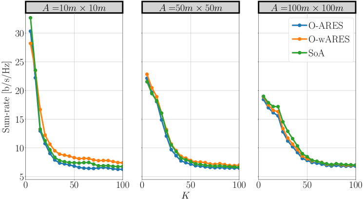
We analyze the viability of self-configuring an HRIS by solving Problem 1 with perfect knowledge of the aggregate HRIS-UE channel and of the response vector of the HRIS towards the BS in (17). We refer to this design as the Oracle (O) scheme, since the channels are assumed to be perfectly known. Moreover, we analyze two solutions that assume real-valued (continuous) phase shifts: ) O-ARES, which calculates , and ) O-weighted ARES (O-wARES), which calculates . Specifically, O-ARES estimates and only based on the directions of the paths that are assumed to have a unit gain, while O-wARES utilizes the direction and the gain of the paths.
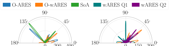
Figure 5 (left) shows a comparison of the HRIS configuration obtained by O-ARES, O-wARES, and the SoA centralized solution in [14], which jointly optimizes the BS precoder and the RIS phase shifts by means of a control channel. While the SoA provides a very directive beampattern with few enhanced directions, both versions of O-ARES result in a wider range of directions at the expense of a smaller gain due to the presence of multiple secondary lobes. Despite the different beampatterns, the sum-rates obtained by ARES and the centralized benchmark, as shown in Fig. 6, are very similar. In particular, O-ARES and the SoA provide a sum-rate that does not increase with the number of UEs, which hints at an interference-constrained scenario. Notably, O-wARES delivers better performance thanks to the weighting mechanism that strengthens the reflected paths with higher power gains.
7.2 Codebook-Based ARES
In this section, we analyze the performance offered by ARES under the realistic assumption that the HRIS optimizes its configuration through power measurements and by iteratively activating the beam patterns (codewords) in the codebook . Therefore, no apriori knowledge of the aggregate channel and of the response vector towards the BS is assumed. Also, the phase shifts applied by the HRIS belong to the discrete set in (31). The steering directions are computed based on the estimated peaks in the measured power profile . Supported by the previous case study, we analyze only the performance of wARES. Based on the estimated angular power profile , and are estimated from (32). The weights are set equal to , and , .
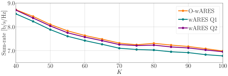
We consider two implementations for wARES, denoted by wARES Q1 and wARES Q2, which correspond to the wARES algorithm with the quantization levels and bits, respectively. The achievable average sum-rate is reported in Fig. 7. Relaxing the assumptions of perfect CSI and continuous phase shifts has only a limited impact on the sum-rate, which confirms the effectiveness of the proposed approach proposed. As expected, the sum-rate worsens when one quantization bit is used, while two quantization bits offer good performance already.
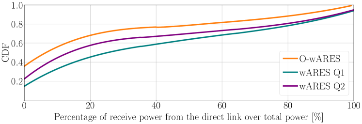
In Fig. 8, finally, we report the distribution of the percentage of power that every UE receives from the direct link with respect to the total received power (from the direct link and the reflected link). We note that O-wARES offers the highest power boost that originates from the reflect paths thanks to its ideal beamforming capabilities. On the other hand, wARES Q and Q are affected by quantization errors that lead to beampatterns with a more distributed power spread. Similar unwanted reflections can be seen in Fig. 5 (right), where the beampatterns obtained with O-wARES and wARES Q and Q are reported. However, these unwanted reflections minimally affect the sum-rate.
7.3 Energy Self-sufficiency
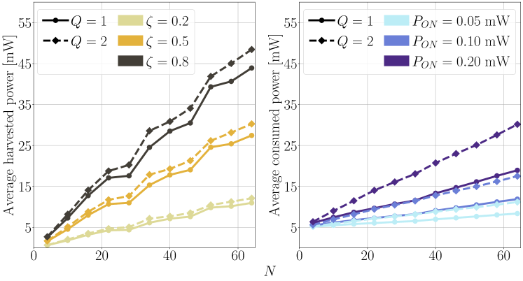
Lastly, we assess the performances of ARES in terms of energy self-sufficiency, starting from the evaluation of the harvested and consumed power, and considering a low SoC threshold . Fig. 9 shows the average harvested (left) and consumed (right) power with different HRIS hardware configurations, and in different traffic conditions. From these results, we derive the statistics of , assuming that it is distributed as a Gaussian RV, i.e., . Moreover, to take into account the power consumption of the HRIS controller, we consider the absorption of mW and mW when the device operates in standard or idle condition, respectively888 The selected values correspond to the power consumption of the run and the stop modes of the STM32L071V8T6 micro controller adopted in the RIS implementation proposed in [7].. The average harvested power has a monotonic increasing behavior concerning the number of meta-atoms composing the surfaces, as the larger the number of elements, the higher the HRIS ability to focus towards the signal sources, which, in turn, grows the harvested power. Similarly, more quantization levels allow for finer granularity in the phase shift selection, further improving the harvesting performance. However, higher values of and increase the complexity of the HRIS hardware, inflating the corresponding overall power consumption. As a result, a novel trade-off arises between the harvested and the consumed powers, whose deviation needs to be compensated by the battery in order to keep the HRIS alive with the desired .
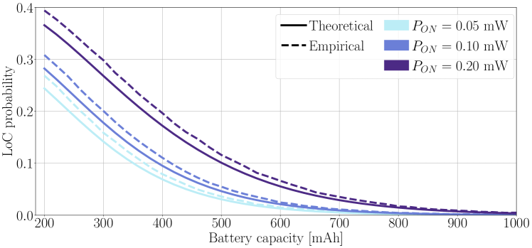
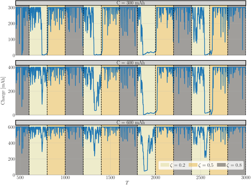
In Fig. 10, we depict the for different sizes of the device battery, and different values of , which directly affects the HRIS power consumption. We consider both the obtained as per (30), denoted as theoretical, and by simulating the charge and discharge processes over reconfiguration periods , denoted as empirical. Besides, we consider a battery voltage of V and set to mAh. As expected, increasing the battery size reduces the LoC probability. However, for high values of , i.e. high overall power consumption, enlarging the size of the battery might not provide adequately low as the harvested power becomes smaller than the overall HRIS hardware consumption. Fig. 11 showcases an example of the battery charge and discharge process for different traffic intensities . In particular, we illustrate how the battery tends to discharge in low-traffic conditions and recharge in higher-traffic conditions. We also confirm that equipping the HRIS with a bigger battery is beneficial for avoiding the LoC as it helps the HRIS not run out of battery during prolonged low-traffic conditions.
8 Conclusions
RISs are an emerging clean-slate technology with the inherent potential of fundamentally reshaping the design and deployment of mobile communication systems. In this paper, we introduced ARES, an Autonomous RIS with Energy harvesting and Self-configuration solution towards 6G, which dismisses the need for a complex ad-hoc control channel and a power supply to operate RISs, bringing up a fully-autonomous RISs solution with no deployment constraint. ARES is built upon ) a new low-complexity hardware design providing HRISs with both sensing and energy harvesting capabilities, ) a channel estimation model lato-sensu at the HRISs, ) an autonomous HRISs configuration methodology operating both on the reflection and on the EH properties of the HRISs, which is based only on locally estimated CSI, without a control channel. ARES achieves communication perfomance comparable with fully CSI-aware benchmark while demonstrating the feasibility of EH for RISs power supply in future deployments.
References
- [1] O. Tsilipakos et al., “Toward Intelligent Metasurfaces: The Progress from Globally Tunable Metasurfaces to Software-Defined Metasurfaces with an Embedded Network of Controllers,” Advanced Optical Materials, vol. 8, no. 17, 2020.
- [2] M. Di Renzo et al., “Smart Radio Environments Empowered by Reconfigurable Intelligent Surfaces: How It Works, State of Research, and The Road Ahead,” IEEE J. Sel. Areas Commun., vol. 38, no. 11, 2020.
- [3] E. C. Strinati et al., “Reconfigurable, Intelligent, and Sustainable Wireless Environments for 6G Smart Connectivity,” IEEE Commun. Mag., vol. 59, no. 10, 2021.
- [4] M. Di Renzo et al., “Smart radio environments empowered by reconfigurable AI meta-surfaces: an idea whose time has come,” EURASIP J. Wireless Commun. Net., vol. 2019, no. 1, May 2019.
- [5] G. C. Alexandropoulos et al., “Hybrid reconfigurable intelligent metasurfaces: Enabling simultaneous tunable reflections and sensing for 6G wireless communications,” arXiv preprint arXiv:2104.04690, 2021.
- [6] A. Albanese et al., “MARISA: A self-configuring metasurfaces absorption and reflection solution towards 6G.” IEEE, 2022.
- [7] M. Rossanese et al., “Designing, Building, and Characterizing RF Switch-based Reconfigurable Intelligent Surfaces,” 2022.
- [8] S. Zeadally et al., “Design architectures for energy harvesting in the internet of things,” Renewable and Sustainable Energy Reviews, vol. 128, 2020.
- [9] H. Liu et al., “ADMM Based Channel Estimation for RISs Aided Millimeter Wave Communications,” IEEE Commun. Lett., vol. 25, no. 9, 2021.
- [10] R. Liang et al., “A Cascaded Multi-IRSs Beamforming Scheme in mmWave Communication Systems,” IEEE Access, vol. 9, 2021.
- [11] Q. Wu and R. Zhang, “Intelligent Reflecting Surface Enhanced Wireless Network via Joint Active and Passive Beamforming,” IEEE Trans. Wireless Commun., vol. 18, no. 11, 2019.
- [12] ——, “Beamforming Optimization for Wireless Network Aided by Intelligent Reflecting Surface With Discrete Phase Shifts,” IEEE Trans. Commun., vol. 68, no. 3, 2020.
- [13] I. Yildirim et al., “Modeling and Analysis of Reconfigurable Intelligent Surfaces for Indoor and Outdoor Applications in Future Wireless Networks,” IEEE Trans. Commun., vol. 69, no. 2, 2021.
- [14] P. Mursia et al., “RISMA: Reconfigurable Intelligent Surfaces Enabling Beamforming for IoT Massive Access,” IEEE J. Sel. Areas Commun., vol. 39, no. 4, 2021.
- [15] M.-M. Zhao et al., “Intelligent reflecting surface enhanced wireless networks: Two-timescale beamforming optimization,” IEEE Trans. Wireless Commun., vol. 20, no. 1, 2020.
- [16] A. Abrardo et al., “Intelligent Reflecting Surfaces: Sum-Rate Optimization Based on Statistical Position Information,” IEEE Trans. Commun., vol. 69, no. 10, 2021.
- [17] K. Zhi et al., “Statistical CSI-Based Design for Reconfigurable Intelligent Surface-Aided Massive MIMO Systems With Direct Links,” IEEE Wireless Commun. Lett., vol. 10, no. 5, 2021.
- [18] N. S. Perović et al., “Achievable Rate Optimization for MIMO Systems With Reconfigurable Intelligent Surfaces,” IEEE Trans. Wireless Commun., vol. 20, no. 6, 2021.
- [19] N. S. Perović et al., “Optimization of RIS-aided MIMO Systems via the Cutoff Rate,” IEEE Wireless Commun. Lett., 2021.
- [20] Q. Wu et al., “Intelligent Reflecting Surface-Aided Wireless Communications: A Tutorial,” IEEE Trans. Commun., vol. 69, no. 5, 2021.
- [21] Y. Li et al., “A Novel 28 GHz Phased Array Antenna for 5G Mobile Communications,” ZTE Communications, vol. 18, no. 3, 2020. [Online]. Available: https://res-www.zte.com.cn/mediares/magazine/publication/com_en/article/202003/202003004.pdf
- [22] G. C. Trichopoulos et al., “Design and Evaluation of Reconfigurable Intelligent Surfaces in Real-World Environment,” vol. 3, 2022.
- [23] L. Dai et al., “Reconfigurable intelligent surface-based wireless communications: Antenna design, prototyping, and experimental results,” IEEE Access, vol. 8, 2020.
- [24] J. Hu et al., “Reconfigurable Intelligent Surface Based RF Sensing: Design, Optimization, and Implementation,” IEEE J. Sel. Areas Commun., vol. 38, no. 11, 2020.
- [25] F. Maresca et al., “A Frequency-Agnostic RIS-based solution to control the Smart Radio Propagation Environment,” 2022.
- [26] R. Fara et al., “Reconfigurable Intelligent Surface-Assisted Ambient Backscatter Communications – Experimental Assessment,” 2021.
- [27] ——, “A Prototype of Reconfigurable Intelligent Surface with Continuous Control of the Reflection Phase,” vol. 29, no. 1, 2022.
- [28] X. Tan et al., “Enabling Indoor Mobile Millimeter-wave Networks Based on Smart Reflect-arrays,” 2018.
- [29] V. Arun and H. Balakrishnan, “RFocus: Beamforming Using Thousands of Passive Antennas,” 2020.
- [30] M. Dunna et al., “ScatterMIMO: enabling virtual MIMO with smart surfaces,” 2020.
- [31] A. E. Lamminen et al., “60-GHz patch antennas and arrays on LTCC with embedded-cavity substrates,” IEEE Trans. Antennas Propag., vol. 56, no. 9, 2008.
- [32] J.-H. Li et al., “A novel thermistor-based RF power sensor with wheatstone bridge fabricating on MEMS membrane,” J. Microelectromech. Syst., vol. 29, no. 5, 2020.
- [33] M. Yasir et al., “Integration of antenna array and self-switching graphene diode for detection at 28 GHz,” IEEE Electron Device Lett., vol. 40, no. 4, 2019.
- [34] L.-G. Tran et al., “RF power harvesting: a review on designing methodologies and applications,” Micro and Nano Systems Letters, vol. 5, no. 1, 2017.
- [35] H. P. Partal et al., “Design and realization of an ultra-low power sensing RF energy harvesting module with its RF and DC sub-components,” Int. J. RF Microw. Comput.-Aided Eng., vol. 29, no. 1, p. e21622, 2019.
- [36] Q. Wu et al., “Intelligent reflecting surface-aided wireless energy and information transmission: An overview,” Proc. IEEE, 2021.
- [37] A. Albanese et al., “RIS-Aware Indoor Network Planning: The Rennes Railway Station Case,” 2022.
- [38] T. L. Marzetta, “Massive MIMO: an introduction,” Bell Labs Technical Journal, vol. 20, 2015.
- [39] A. Alkhateeb et al., “Initial Beam Association in Millimeter Wave Cellular Systems: Analysis and Design Insights,” IEEE Trans. Wireless Commun., vol. 16, no. 5, 2017.
- [40] Y. Chen et al., “Wireless Energy Harvesting Using Signals From Multiple Fading Channels,” IEEE Trans. Commun., vol. 65, no. 11, 2017 .
- [41] Y.-z. Li, R. Luan, and J.-c. Niu, “Forecast of power generation for grid-connected photovoltaic system based on grey model and Markov chain,” in IEEE Conf. on Ind. Electron. Appl., 2008, pp. 1729–1733.
- [42] J. Song et al., “Development of a Markov-chain-based energy storage model for power supply availability assessment of photovoltaic generation plants,” IEEE Trans. Sustain. Energy, vol. 4, no. 2, 2012.
- [43] A. Albanese et al., “RIS-Aware Indoor Network Planning: The Rennes Railway Station Case,” 2022.
- [44] J. He et al., “Adaptive Beamforming Design for mmWave RIS-Aided Joint Localization and Communication,” 2020.
- [45] T. Boles et al., “AlGaAs PIN diode multi-octave, mmW switches.” IEEE, 2011.
- [46] L. Petrou et al., “The first family of application-specific integrated circuits for programmable and reconfigurable metasurfaces,” Scientific reports, vol. 12, no. 1, 2022.
- [47] M. Gapeyenko et al., “On the temporal effects of mobile blockers in urban millimeter-wave cellular scenarios,” IEEE Trans. Veh. Technol., vol. 66, no. 11, 2017.
- [48] A. Zappone et al., “Overhead-aware design of reconfigurable intelligent surfaces in smart radio environments,” IEEE Trans. Wireless Commun., vol. 20, no. 1, 2020.
- [49] I. Rouissi et al., “Design of a frequency reconfigurable patch antenna using capacitive loading and varactor diode.” IEEE, 2015.