Spontaneous Skyrmion Conformal Lattice and Transverse Motion During dc and ac Compression
Abstract
We use atomistic-based simulations to investigate the behavior of ferromagnetic skyrmions being continuously compressed against a rigid wall under dc and ac drives. The compressed skyrmions can be annihilated close to the wall and form a conformal crystal with both a size and a density gradient, making it distinct from conformal crystals observed previously for superconducting vortices and colloidal particles. For both dc and ac driving, the skyrmions can move transverse to the compression direction due to a combination of density and size gradients. Forces in the compression direction are converted by the Magnus force into transverse motion. Under ac driving, the amount of skyrmion annihilation is reduced and we find a skyrmion Magnus ratchet pump. We also observe shear banding in which skyrmions near the wall move up to twice as fast as skyrmions further from the wall. When we vary the magnitude of the applied drive, we find a critical current above which the skyrmions are completely annihilated during a time scale that depends on the magnitude of the drive. By varying the magnetic parameters, we find that the transverse motion is strongly dependent on the skyrmion size. Smaller skyrmions are more rigid, which interferes with the size gradient and destroys the transverse motion. We also confirm the role of the size gradient by comparing our atomistic simulations with a particle-based model, where we find that the transverse motion is only transient. Our results are relevant for applications where skyrmions encounter repulsive magnetic walls, domain walls, or interfaces.
Keywords: Skyrmion, conformal crystal, compression
1 Introduction
Skyrmions are particle like magnetic objects that arise in chiral magnets [1, 2, 3]. Their size scale, mobility, and stability makes them excellent candidates for spintronic and logic devices [3, 4, 5]. Due to their gyrotropic properties, skyrmions are also of interest for understanding new types of collective dynamics in nanostructured systems [3, 4, 6]. Many of the proposed applications of skyrmions require them to be moved with ac or dc driving, making it important to identify possible ways to control the motion and stability of ferromagnetic skyrmions [7, 8, 9, 10, 11, 12]. Skyrmions have many similarities to other particle-like objects such as superconducting vortices, colloids, and electrons in Wigner crystals. In these systems the particle-like objects organize themselves into triangular lattices, can be set into motion with an external drive, and can interact with quenched disorder or pinning [13]. There are several differences between skyrmions and other overdamped systems. Skyrmions experience a strong non-dissipative Magnus force that can create a velocity component perpendicular to the external forces, and the sign of this force depends on the topological charge of the skyrmion [14, 15, 16, 17, 6, 3, 18]. When subjected to a spin current in a clean sample without defects, skyrmions move at an angle, known as the intrinsic skyrmion Hall angle [14, 15, 16, 17, 6, 3], to the applied driving force. Experimentally observed skyrmion Hall angles span the range from a few degrees up to , depending on the system parameters and the skyrmion size [15, 18, 14, 13, 19], and much larger angles should be possible [3, 13]. Skyrmions with different sizes can be stabilized in a given sample, and the gyrotropic effects are stronger for smaller skyrmions and weaker for larger ones, meaning that skyrmions of different size move with different intrinsic skyrmion Hall angles. [18, 14, 5].
There is increasing interest in identifying ways to control individual and collective skyrmion motion. Possible methods include periodic pinning [20, 21, 22, 23, 24, 25, 26, 27, 28], ratchet effects [29, 30, 31, 32, 33, 34], interface guided motion [35, 36], strain, magnetic or temperature gradients [37, 38, 39, 40], one-dimensional potential wells [41], and skyrmion-vortex coupling using a ferromagnet-superconductor heterostructure [42]. Skyrmions can also be manipulated by being compressed against a wall or linear obstacle, such as by applying a drive that forces the skyrmions to move toward an interface or extended nanostructure. Another possibility would be to move some form of domain wall against the edge of the skyrmion lattice.
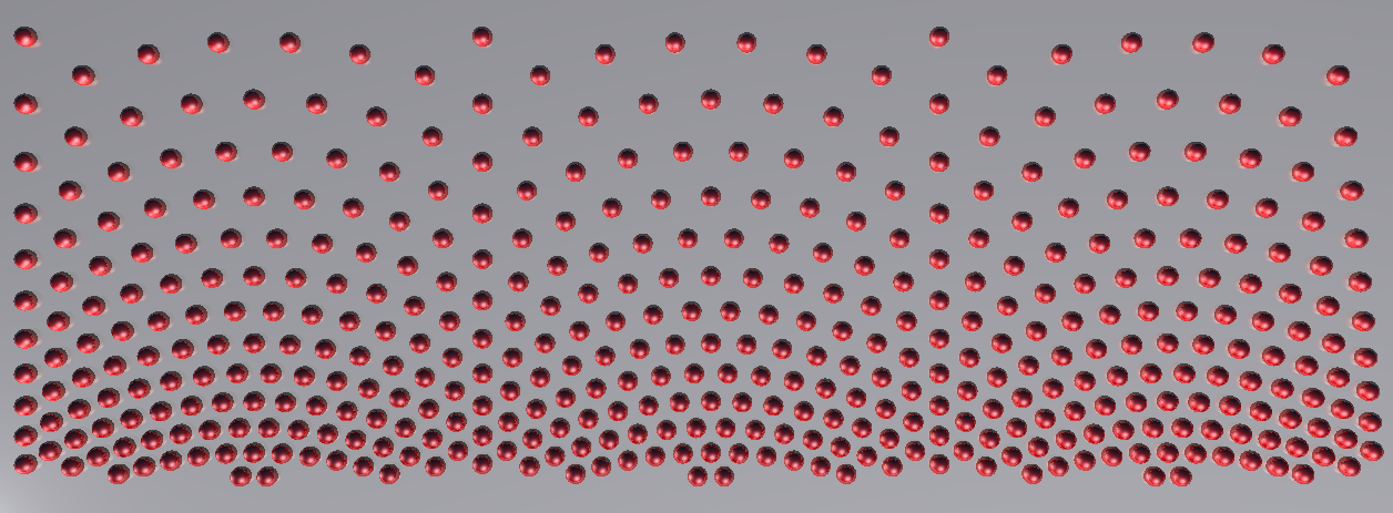
The behavior of overdamped particles such as superconducting vortices and colloids under compression has been examined previously. In a uniform crystal, the spacing between particles is fixed, so under compression it can be difficult for the sample to reconfigure into a new uniform crystal with a smaller lattice constant. Studies of magnetically interacting particles being pushed toward a wall showed that the particles form a density gradient composed of an array of arcs in a shape known as a conformal crystal [43, 44]. A perfect conformal crystal is produced by conformally transforming a two-dimensional uniform lattice. In the transformed structure, a density gradient is present but the angles between nearest neighbors in the original lattice are preserved and there are no topological defects. The experiments in Refs. [43, 44] produced a conformal structure containing some topological defects. In figure 1 we show an example of a perfect two-dimensional conformal crystal without defects. Simulations of superconducting vortices interacting with pinning sites that have a conformal crystal arrangement showed that such a substrate produces optimal pinning in samples where the vortices enter from one side and develop a natural density gradient [45], a result that was then confirmed in experiment [46].
Menezes et al. numerically studied a crystal of type II superconducting vortices, which have softer intermediate-range interactions than the magnetic particles, being pushed against a wall by a current [47]. They showed that under these conditions, a conformal vortex lattice forms spontaneously. Further studies explored conformal structures in circular geometries [48] and with different types of defects [49]. These studies focused only on the final static conformal states and did not address the dynamics during compression.
Since magnetic skyrmions also organize themselves in a triangular array and have soft repulsive interactions, it should be possible to form a conformal crystal by compressing a skyrmion lattice, similar to observations for colloidal particles and superconducting vortices. In overdamped systems, the particles move in the direction of the net force they experience, so application of a dc or ac compression is not expected to produce motion transverse to the compression direction. In the case of skyrmions, however, the Magnus force dominates the dynamics and generates a velocity component perpendicular to the net applied force. Additionally, previous studies involving conformal crystals were performed with stiff particles that have no internal degrees of freedom; however, skyrmions can change size in response to their environment, and the dynamics of the skyrmion are affected by the size of the skyrmion.
In previous work, Zhang et al. [50] examined skyrmions under compression against a wall and focused on structural transitions in the skyrmion lattice. No conformal arrangement appeared in this work, however, since only a portion of the skyrmions were being compressed while the remaining skyrmions served as pinning obstacles. Zhang et al. showed that a lattice structural transition can be induced by compression, and that near the injection boundary separating the driving and compressive regions, the skyrmions may flow in chains.
In this work, we perform atomistic simulations of the dynamics of multiple skyrmions being compressed against a rigid wall by dc or ac drives applied perpendicular to the wall. This work is distinct from that of Ref. [50] since we apply the drive to all of the skyrmions, which should be a realistic situation for experiments on skyrmions moving against the edge of a nanofabricated structure. We show that the skyrmions accumulate near the wall and assemble into a conformal crystal, and we study the dynamical formation of this structure. The skyrmions gradually change in size from larger to smaller as they approach the wall, leading to a size gradient in the conformal crystal, different from what is observed for colloids and superconducting vortices. Under dc driving, after the skyrmions have formed a compressed conformal crystal, they all move as a jammed packing in the direction. In addition, the constant compressing current leads to constant skyrmion annihilation.
Under an ac rectified drive, we still observe an initial compression of the skyrmion lattice followed by transverse motion of the skyrmions along the direction. In addition, there is a clear shear banding in which skyrmions closer to the wall move much faster than skyrmions far from the wall. The skyrmion annihilation is reduced due to a relaxation time introduced by the ac driving. When the current is in the off state, the compression of the skyrmion lattice is relieved, enabling a larger number of skyrmions to be sustained inside the sample over longer periods of time compared to what we observe under dc driving.
We also confirm that the skyrmion size gradient and the resulting spatial gradient in the skyrmion Hall angle is crucial for producing the transverse motion. We compare our atomistic results with simulations of a particle-based model of rigid skyrmions that have fixed size and fixed intrinsic skyrmion Hall angle. In the particle-based model, the motion in the transverse direction is transient and vanishes as time evolves.
2 Simulation
We simulate a ferromagnetic thin film that supports the presence of Neél skyrmions at K under a magnetic field of magnitude applied perpendicular to the film plane, . Here is the strength of the Dzyaloshinskii-Moriya interaction and is the strength of the exchange interaction. The film has infinite dimensions in the and directions, but we introduce a rigid wall at . We use atomistic model simulations [51] to stabilize a skyrmion lattice in the sample with the following Hamiltonian [52, 6, 53]:
| (1) |
The first term on the right hand side is the exchange interaction between adjacent spins and , the second term is the interfacial Dzyaloshinskii-Moriya interaction in the thin film, the third term is the Zeeman interaction due to the application of the magnetic field, where is the magnitude of the local atomic spin moment, and the last two terms are the out of plane magnetic anisotropies [6, 52, 54, 55] consisting of the sample anisotropy (fourth term) and the wall anisotropy (fifth term). We only consider interactions with the first neighbors, given by the set . The wall at which the skyrmion lattice is compressed is modeled using magnetic uniaxial anisotropy defects at , where we set . The spins composing the wall are in the set .
We apply a spin transport current along the direction in order to push the skyrmions towards the wall. The spin time evolution is given by the LLG equation [52, 6, 53]:
| (2) |
Here is the gyromagnetic ratio given by , is the Gilbert damping parameter, is the effective field, is the local spin magnetic moment, and the last term corresponds to the applied current, where is the polarization, is the electron charge, and is the lattice constant. This is called the spin-transfer-torque term, and it includes the assumption that the conduction electron spins are parallel to the local magnetic moments [6, 56].
We consider two different types of applied current. The first is a dc applied current with . The second is rectified ac driving given by:
| (3) |
where is time and is the oscillation frequency. This ac current consists of two stages, one with , referred to throughout the work as the compression cycle, and one in which the drive is absent, referred to as the relaxation cycle.
Since skyrmions carry topological charge, in order to quantify the number of skyrmions in the sample, we measure the net topological charge in the sample , given in the continuum limit by [6, 54, 30, 10, 57, 53]
| (4) |
We are performing atomistic simulations, and therefore the discrete nature of the atomic lattice must be taken into account by computing the skyrmion charge with a discrete sum instead of an integral:
| (5) |
The consequence of this discreteness is that the charge of an individual skyrmion is not always equal to . Instead, it depends on the skyrmion size, and larger skyrmions have closer to [57].
We also calculate the skyrmion velocities using the emergent electromagnetic fields [53]:
| (6) |
where is the totally anti-symmetric tensor. The drift velocity is then computed according to [53, 58]. From the velocities we determine the skyrmion displacement as .
Throughout the simulation we fix , and Å. Unless otherwise noted, we assume the following values for the material parameters: , , , , and .
We use the Runge-Kutta fourth order integration method. The integration is done by normalizing the time in dimensionless units . The current is also normalized in dimensionless units .
3 Compression and Dynamics Under a dc drive
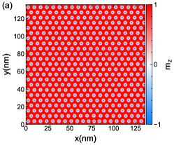
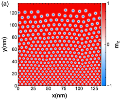
We first consider the case of skyrmions being pushed towards the wall with a fixed dc spin current , where . The system is initialized by stabilizing a skyrmion lattice in the absence of a spin current using an applied magnetic field . As can be seen in figure 2(a), skyrmions organize themselves in a perfect triangular lattice as expected. As the external spin current is applied along the direction, the skyrmions begin to move and the lattice starts to compress against the wall, as shown in figure 2(b). The perfect triangular orientation of the lattice is destroyed due to the stress induced by the external drive. As the drive becomes stronger, the skyrmion lattice stabilizes and reorganizes into a conformal lattice structure as shown in figure 2(c). This structure is very similar to the conformal vortex crystals found by Menezes and de Souza Silva in type II superconductors [47]. In a perfect conformal crystal, illustrated in figure 1, there are no defects; however, in both the magnetic colloid and superconducting vortex systems [43, 47], defects are present, similar to what we find in figure 2(c). The wavelength of the arch structure in the conformal crystal decreases as the amount of compression increases, so in a sample of the size we consider, multiple arches appear if we increase the compression beyond what is shown in figure 2(c). Two aspects of the skyrmion conformal crystal structure differ from previous conformal crystal observations. First, the crystal is not static but is moving in the direction, transverse to the compression. Second, we find a skyrmion size gradient in which skyrmions near the wall are smaller while skyrmions far from the wall are larger.
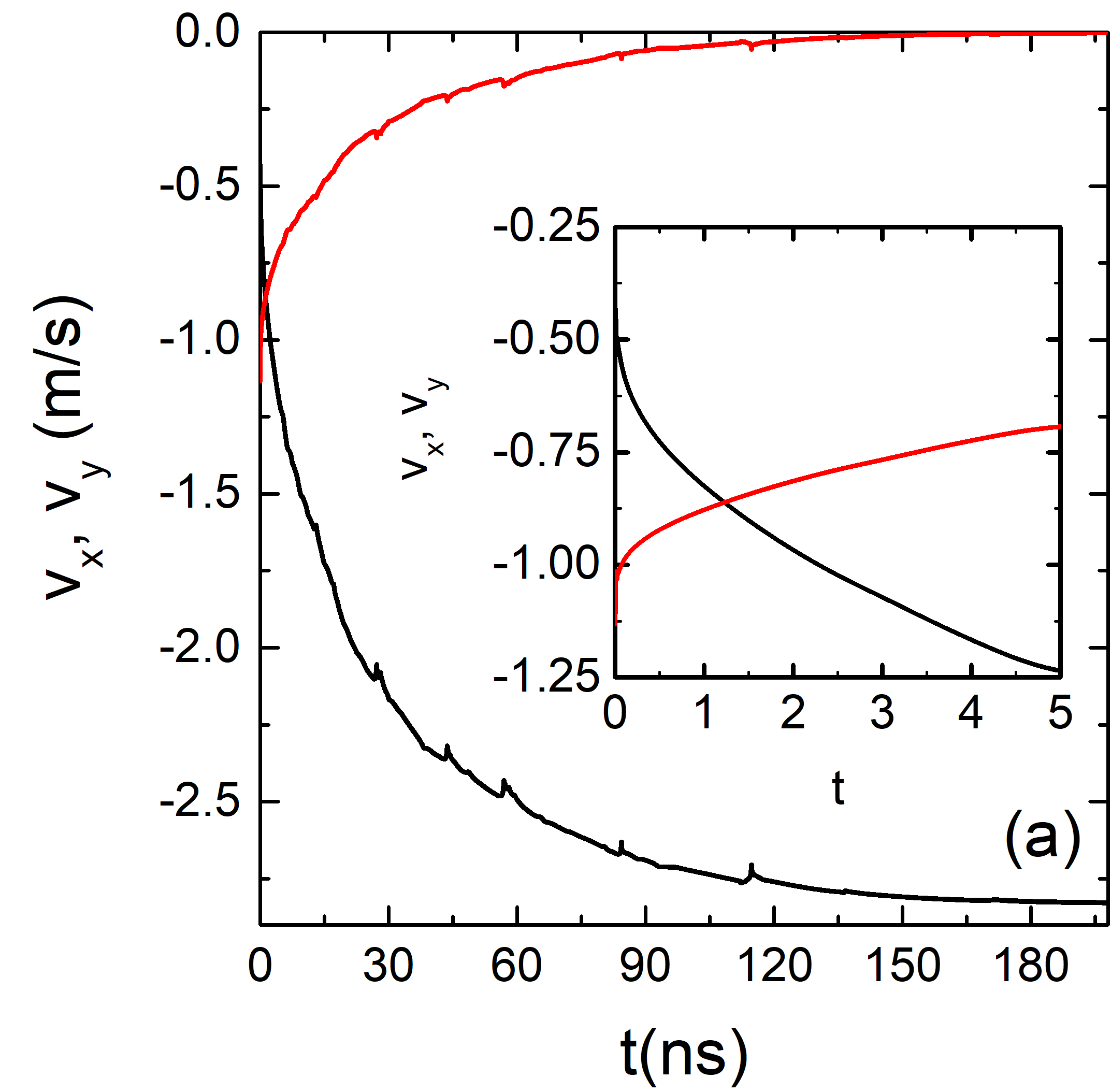
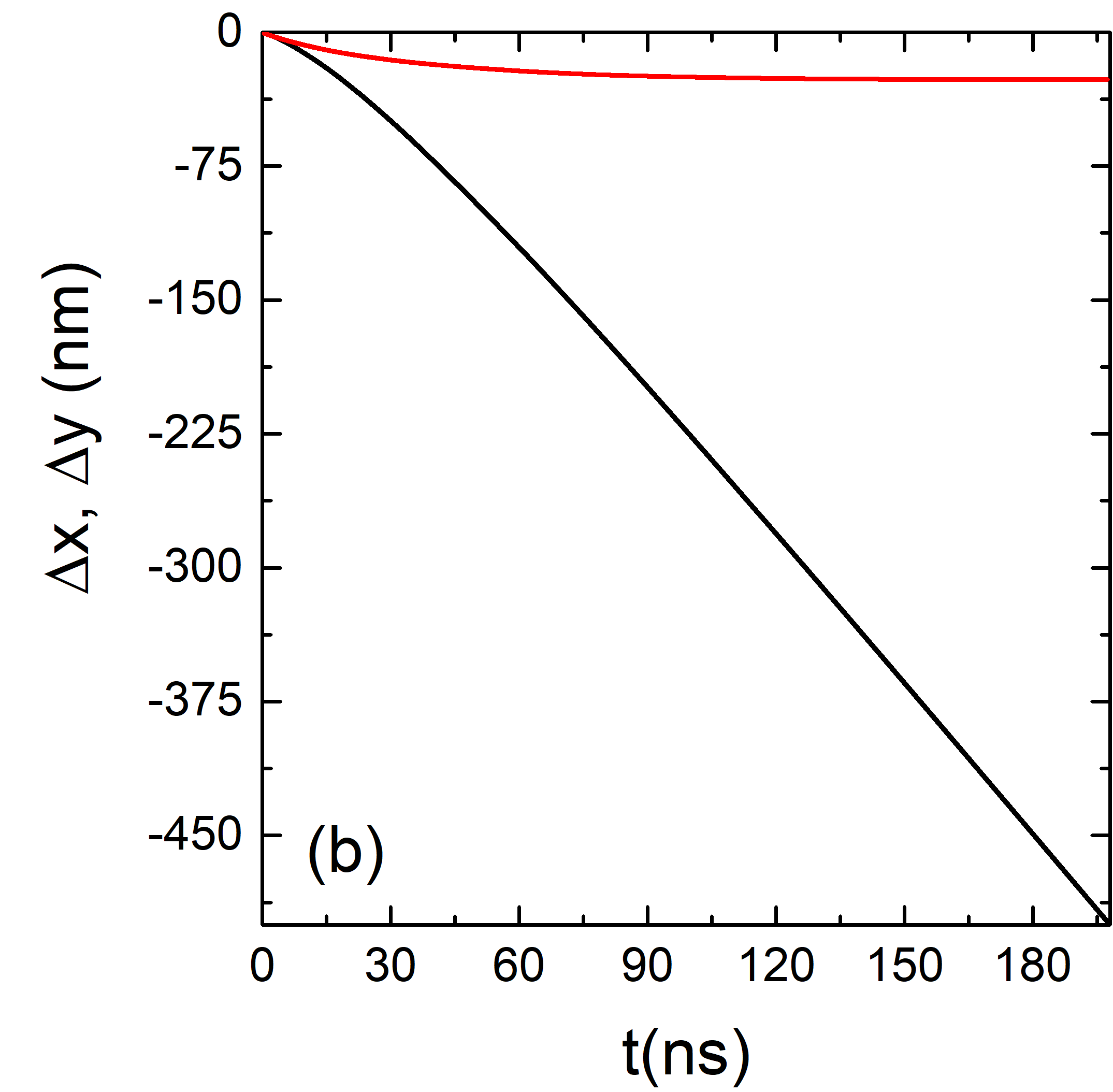
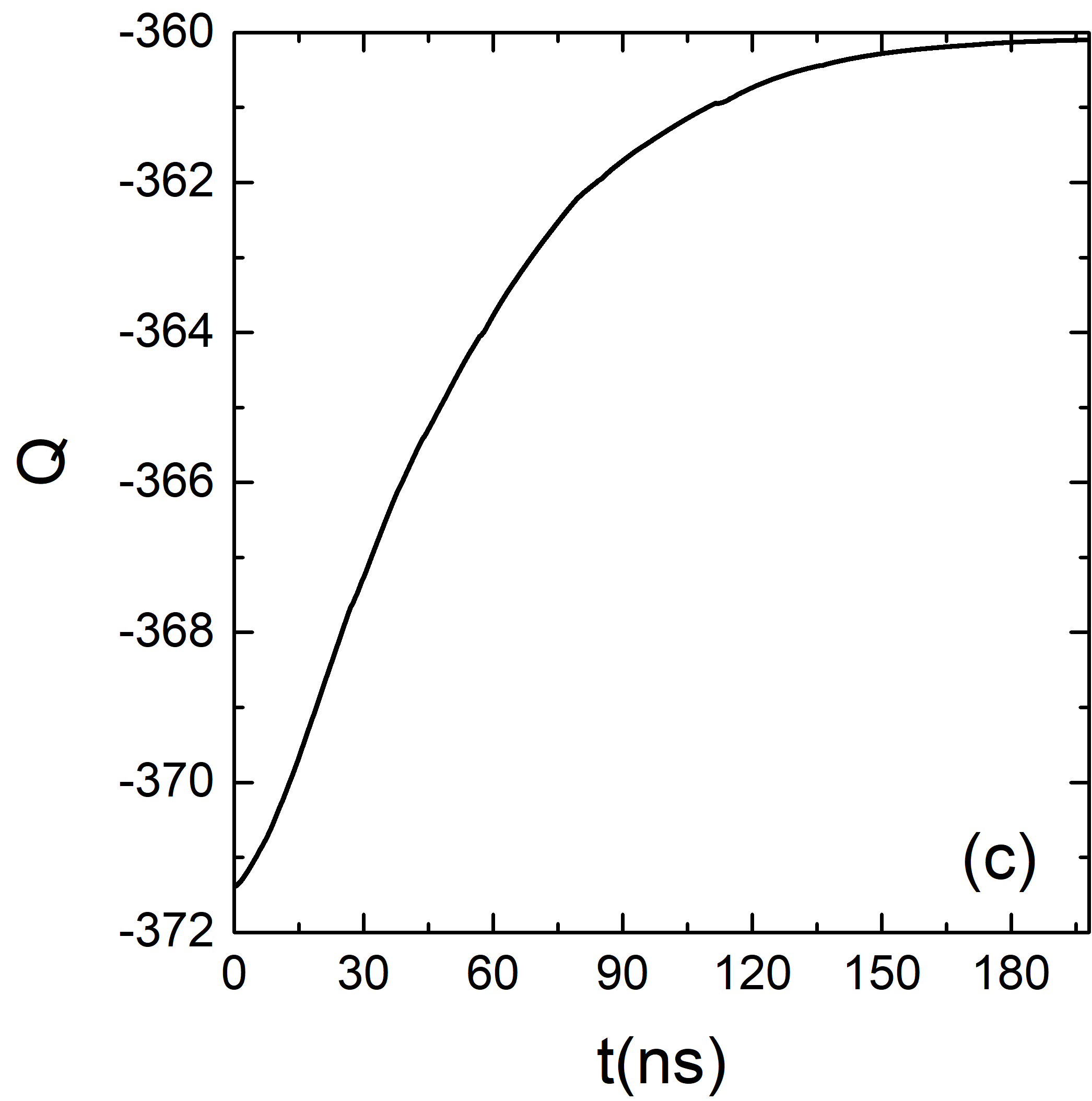
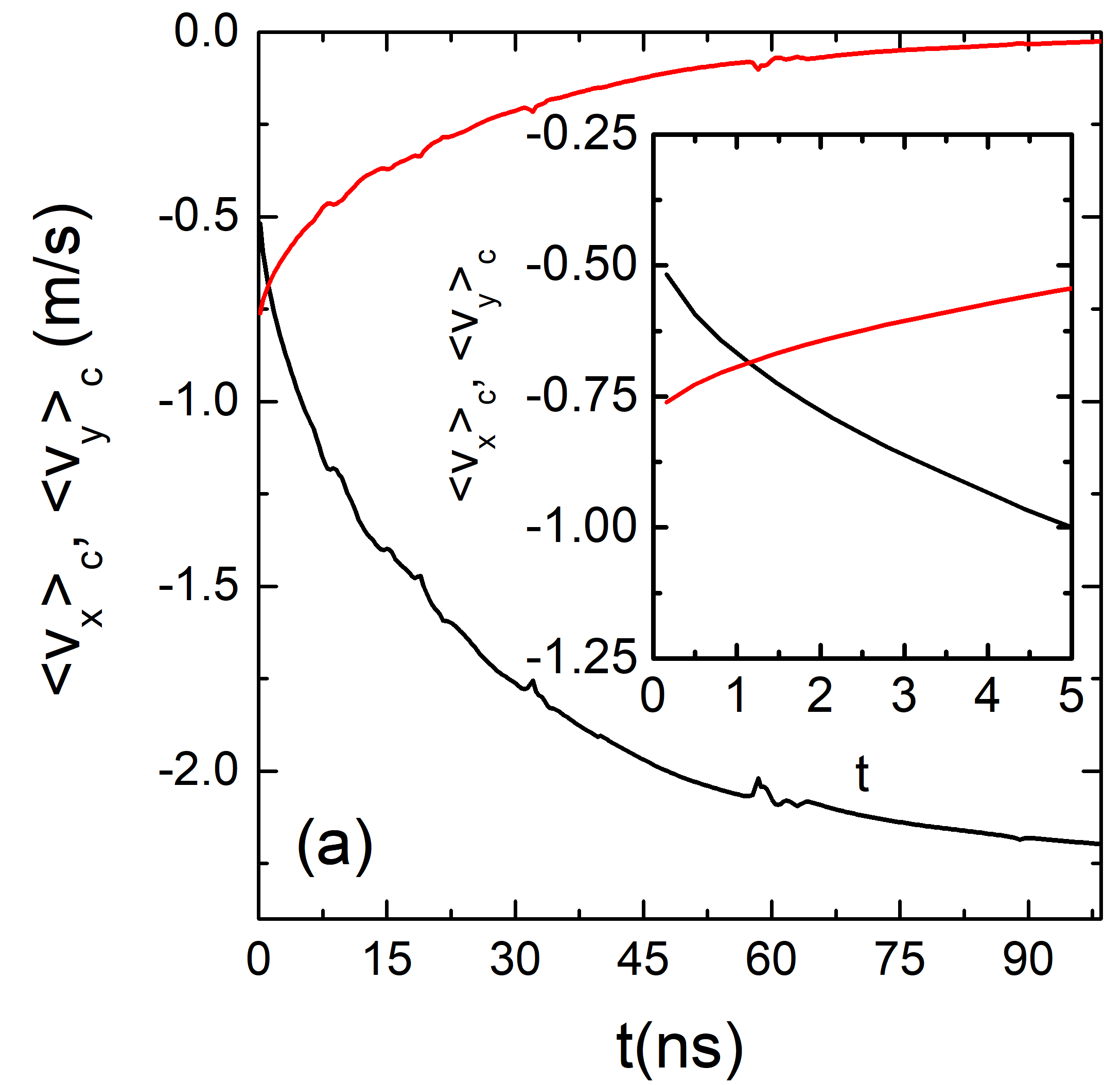
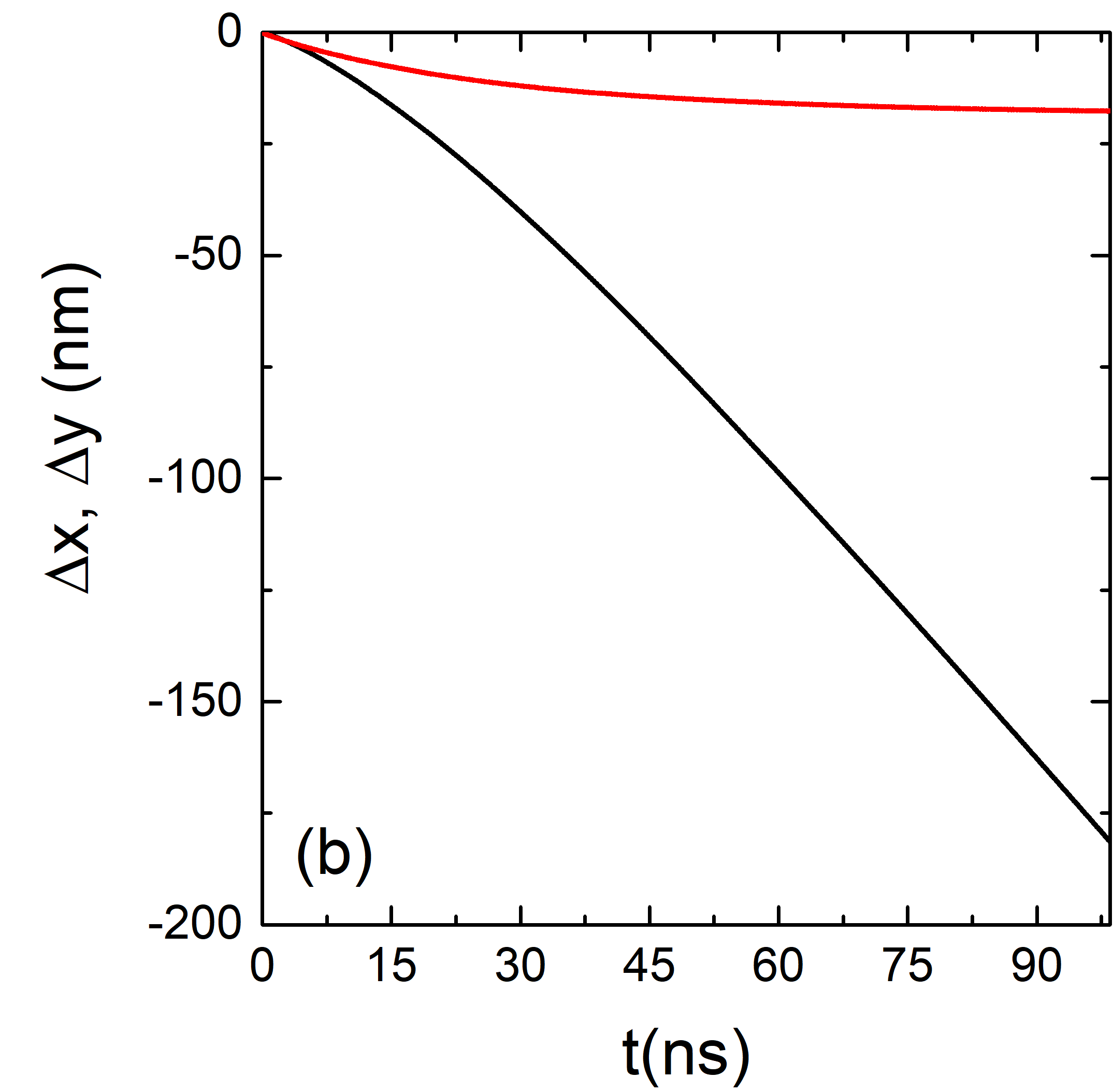
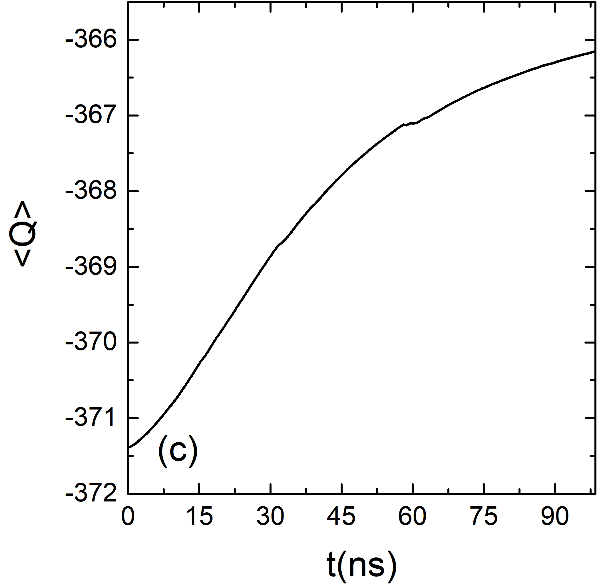
To illustrate the motion of the skyrmion conformal crystal, in figure 3(a) we show the average skyrmion velocity components and as a function of time. We obtain and by summing the instantaneous velocity of all skyrmions and dividing by the number of skyrmions present at time . The external drive is applied beginning at ns. As shown in the inset of figure 3(a), for ns. During this time period, the external drive pushing skyrmions in the direction dominates the dynamics. Skyrmion-wall and skyrmion-skyrmion interactions become important for ns and the dynamics changes drastically, with increasing in magnitude and decreasing in magnitude exponentially until reaching saturation values of m/s and m/s, respectively. At saturation, the skyrmions have organized into the conformal lattice illustrated in figure 2(c) and move with a constant velocity in the direction. This is different than what was observed in the superconducting vortex systems considered by Menezes and de Souza Silva [47], where the conformal vortex lattice is static. There are some small spikes in and in figure 3(a) that are correlated with skyrmion annihilation events or structural rearrangements that occur as the skyrmions are compressed. In figure 3(b) we plot the skyrmion displacements and with respect to the positions, and find that continuously increases with time, while saturates at a maximum displacement of nm. This is the maximum compression that the lattice can endure in the direction due to the combination of external drive, skyrmion-skyrmion, and skyrmion-wall interactions. Figure 3(c) shows the topological charge in the sample as a function of time. This measurement allows us to quantify the change in the number and size of skyrmions in the sample. Higher values of indicate that more and/or larger skyrmions are present, while lower values indicate that the number and/or size of the skyrmions has been reduced. We find a nonmonotonic behavior in the rate of change of , with an increasingly rapid reduction in with time for ns, a steady reduction in for , and a decreasing rate of reduction in for ns. At long times, the topological charge stabilizes around , indicating that the size and number of skyrmions reaches a steady value.
A simple explanation for the appearance of transverse motion is that, due to the presence of the Magnus force, the skyrmion structure can be viewed as a system with odd viscosity, which creates flows perpendicular to any pressure gradients [59]. Additionally there have been several studies investigating the enhancement of motion for a skyrmion approaching a wall, known as a speed-up effect [13, 60, 29, 61, 34, 62]. There have also been experiments on driven skyrmions in which it was observed that, due to the skyrmion Hall angle, skyrmions accumulate along the wall creating a skyrmion density gradient [63]. This experimental study was performed in the low density limit, but we expect that a conformal structure would have formed if a crystalline lattice had been driven. In this work we focus on driving only in the direction. It would also be possible to apply a current along the -direction so that the skyrmion Hall effect drives the skyrmions toward the wall, also creating a conformal structure. In this case, motion along the direction would be produced directly by the spin current, but there would also be a speed-up effect from the Magnus force for skyrmions near the wall.
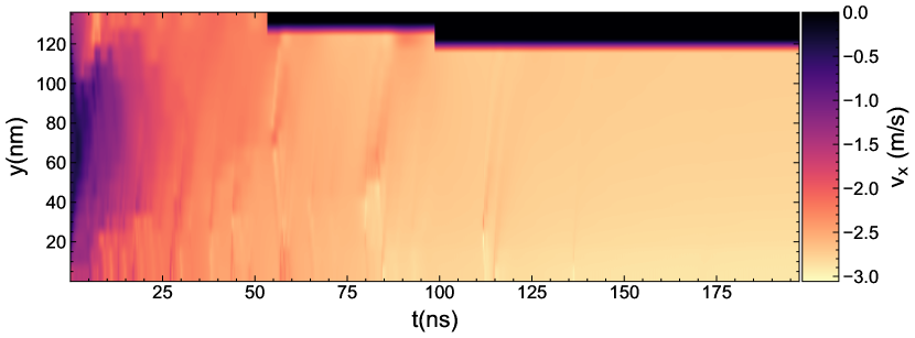
For a better representation of the velocity distribution inside the sample, in figure 4 we plot a heatmap of the skyrmion velocity as a function of the distance from the wall, , and time, . At early times, the external drive compresses the lattice and tends to move the upper and lower skyrmions in a chain of motion. This behavior is similar to that observed by Zhang et al. [50], where a compressing drive produced chain-like motion of skyrmions along the boundary between the driven and non-driven skyrmions. Here, our simulation shows that the skyrmions in the central part of the sample are the last to begin moving, which happens only when the system is completely jammed. In addition, figure 4 clearly shows that for ns all skyrmions move with the same , indicating that the conformal skyrmion lattice translates as a rigid object.
4 Compression under rectified ac drive
We next consider the effects of applying a rectified ac drive, where the drive cycle has two stages: (i) a compressing drive acting on the skyrmions, which we refer to as the compression cycle, and (ii) the drive is absent and the skyrmion-skyrmion and skyrmion-wall interactions are dominant, which we refer to as the relaxation cycle. The spin current is given by equation 3 using .
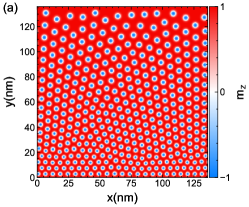
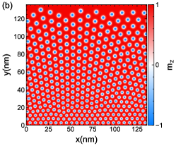
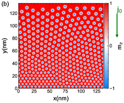
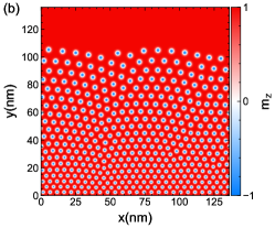
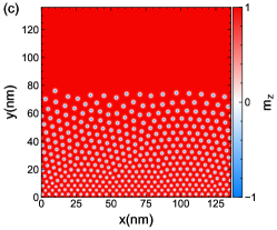
Figure 5 illustrates some spin configurations for a system with an applied magnetic field of under rectified ac driving. The initial configuration at ns, in the absence of an applied drive, is the same as what is shown in figure 2(a), where the skyrmions organize into a triangular lattice. When the ac drive is applied, the skyrmions begin to be pushed towards the wall, but due to the alternation of compression and relaxation cycles, the skyrmions do not become as compressed as in the case of dc driving. In figure 5(a) at ns, the skyrmion lattice is no longer triangular but has a clear density gradient along the direction. For ns in figure 5(b), the skyrmions organize in a compressed configuration that is partially conformal. Note that this is different than what we find for dc driving, where due to the constant compressing force, the conformal lattice is more stable. Under ac driving, the skyrmions are less tightly packed than in the case of dc driving. For higher amplitude ac driving, the skyrmions develop a more strongly conformal structure during the compression cycle.
In figure 6(a) we plot the skyrmion average velocity per ac drive cycle and as a function of time, . Here we average the velocity over all skyrmions during the duration of a given ac cycle. The general behavior of the velocity curves is similar to that found under dc driving. The main difference is in the magnitude of the velocities, where we find that ac driving produces slower motion along the direction compared to dc driving. There is also a reduction in the length of time during which the magnitude of the perpendicular velocity is smaller than that of the parallel velocity, and we find that after ns. We obtain saturation velocity values of m/s and m/s. In figure 6(b) we plot the skyrmion displacements and from the positions as a function of time. The maximum displacement in the direction due to compression is nm, smaller than the value found for dc driving. Figure 6(c) shows the average topological charge during the ac cycle, , as a function of time, . The magnitude of decreases with time, similar to what we observe for dc driving.
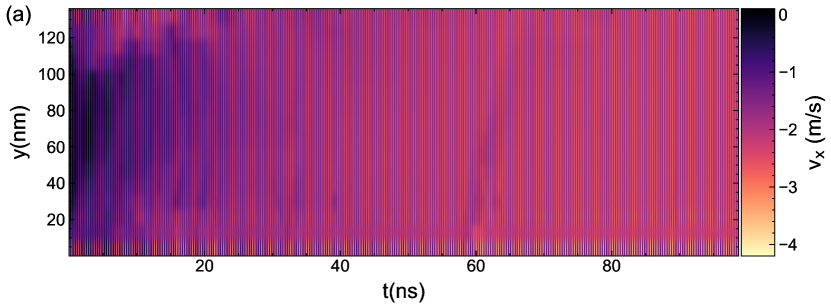
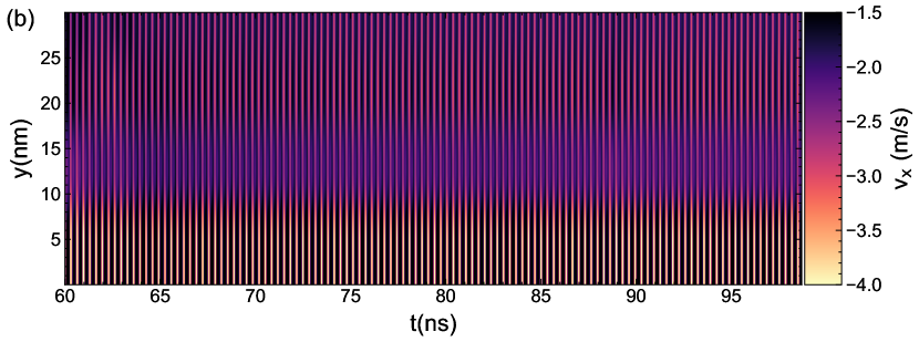
The main difference between ac and dc driving is visible in figure 7, where we plot a heatmap of the skyrmion velocities as a function of distance from the wall and time . This plot provides detailed information on the distribution of the skyrmion velocities inside the sample. For ns, the skyrmions in the upper and lower parts of the sample are moving the most rapidly while the skyrmions in the central part of the sample remain mostly stationary. This is similar to the observations made by Zhang et al. [50] and to what we find under dc driving. What is different is that the skyrmions very close to the wall, nm, exhibit much larger magnitudes of than skyrmions elsewhere in the sample. This is emphasized in figure 7(b), where we plot a blowup of the heatmap in the region near the wall for ns. The compression cycle of the ac drive increases the pressure on the skyrmions at the bottom of the sample, leading to deformations in the skyrmion lattice structure and a reduction in the size of the skyrmions. During the relaxation cycle, these deformed skyrmions relieve the pressure by expanding back out to their equilibrium sizes and pushing the rest of the skyrmions away from the wall. The repeated cycle of compression and release acts as a skyrmion flux pump that accelerates the skyrmions in the bottom part of the sample. This process also produces a shear banding effect in which the skyrmions closest to the wall move much more rapidly than the other skyrmions. Skyrmion velocities in the region nm can reach values of up to m/s, while the average velocities elsewhere in the sample are around m/s.
5 The influence of
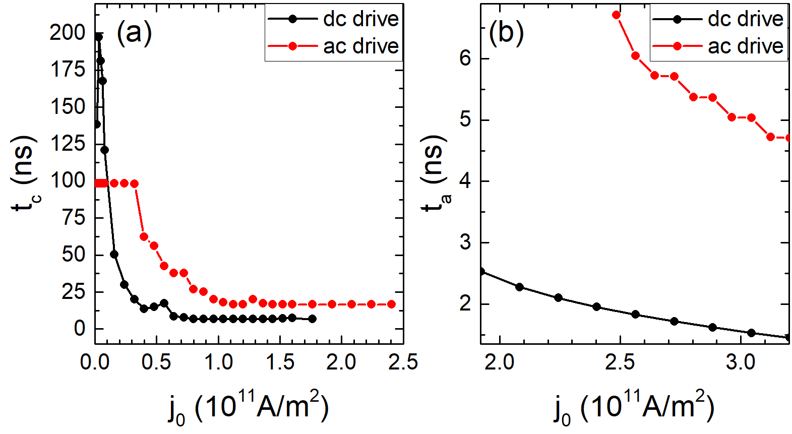
We next analyze how varying the magnitude of the external drive affects the skyrmion lattice structure and annihilation processes. Figure 8 shows results for both dc and ac driving. In figure 8(a) we plot the time at which the skyrmion lattice reaches its maximum compression versus . For , the skyrmion adopts a stable configuration. For low drives of , is smaller for ac driving than for dc driving. This is because the shear banding compression and relaxation cycles in the ac driven system more rapidly compactify the skyrmion lattice. In contrast, for , the skyrmion lattice compresses faster under dc driving since the constant pushing force at these higher currents becomes more efficient than the shear banding organization process.
We find that there is a critical current above which the annihilation of skyrmions does not stop but continues until all of the skyrmions have been annihilated at the wall. We obtain for dc driving and for ac driving. For , it still takes a time for all of the skyrmions to annihilate completely. In figure 8(b) we plot versus for dc and ac driving. The skyrmion lattice survives almost three times as long under ac driving compared to dc driving. In the case of ac driving, the skyrmions are being pushed towards the wall during the compression cycle, but during the relaxation cycle the skyrmions have the same amount of time to relieve the pressure, reorganize their lattice, and avoid annihilation. In contrast, the dc drive system constantly pushes the skyrmions towards the wall, continuously shrinking the skyrmions and favoring their annihilation.
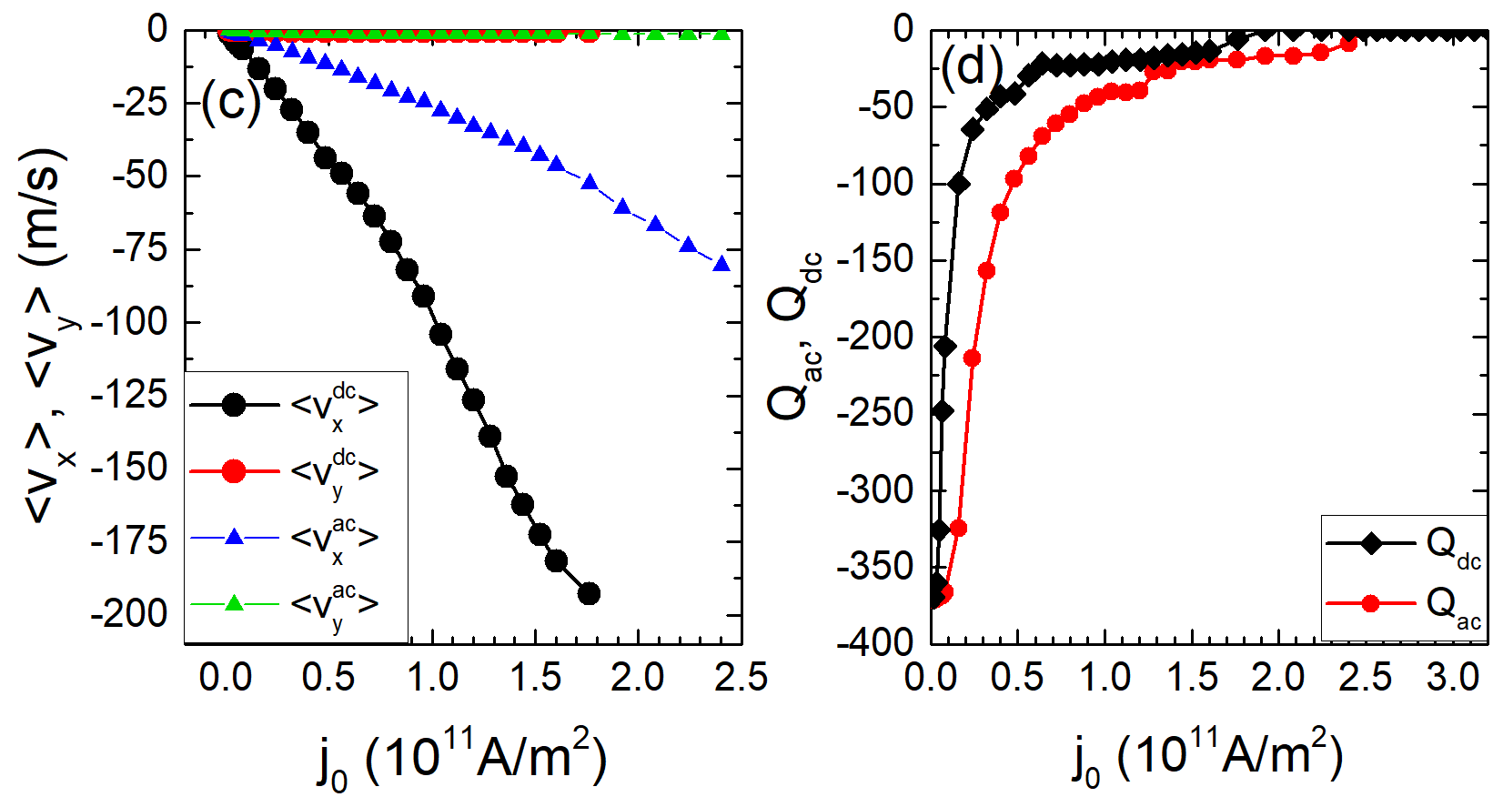
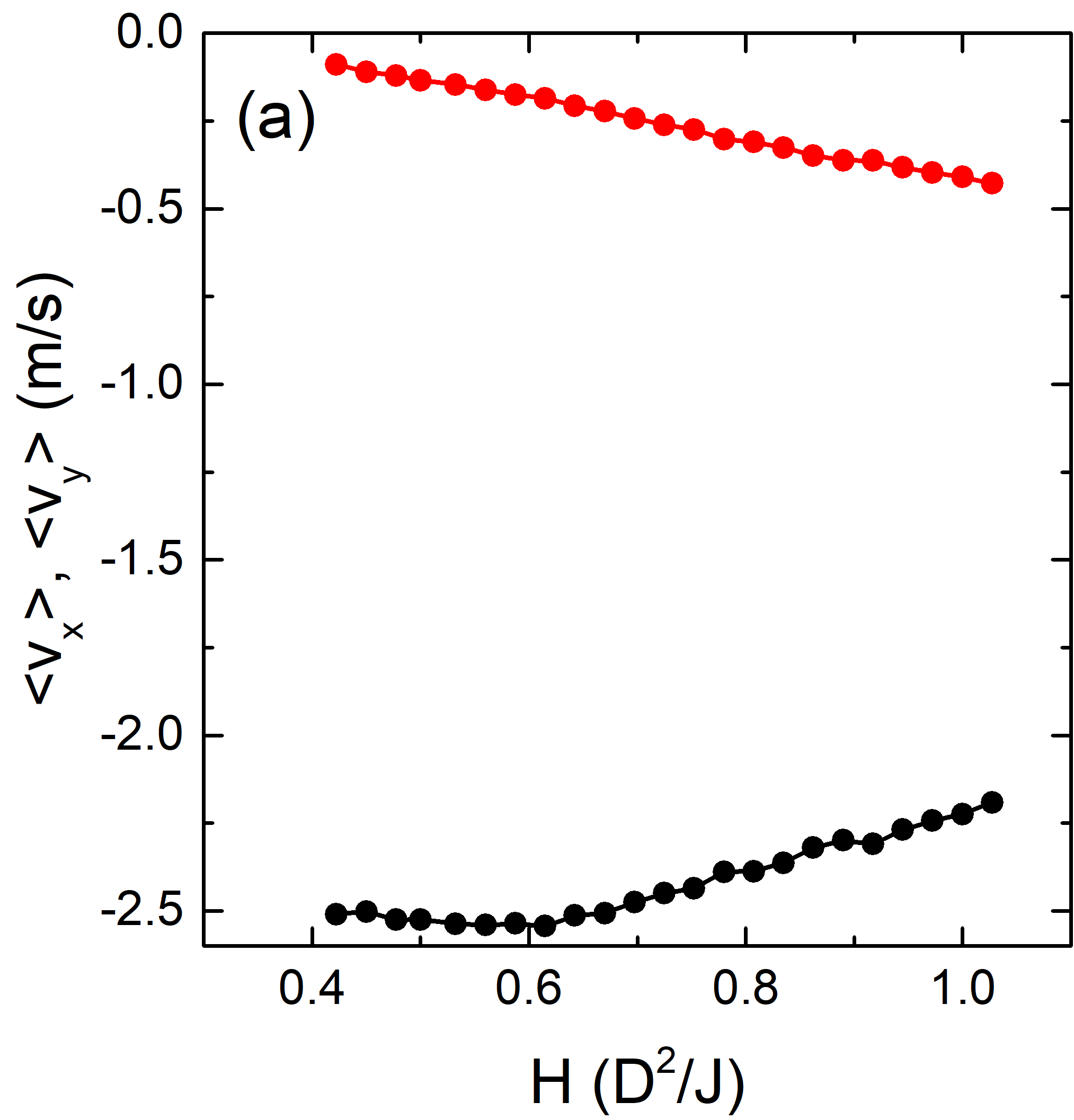
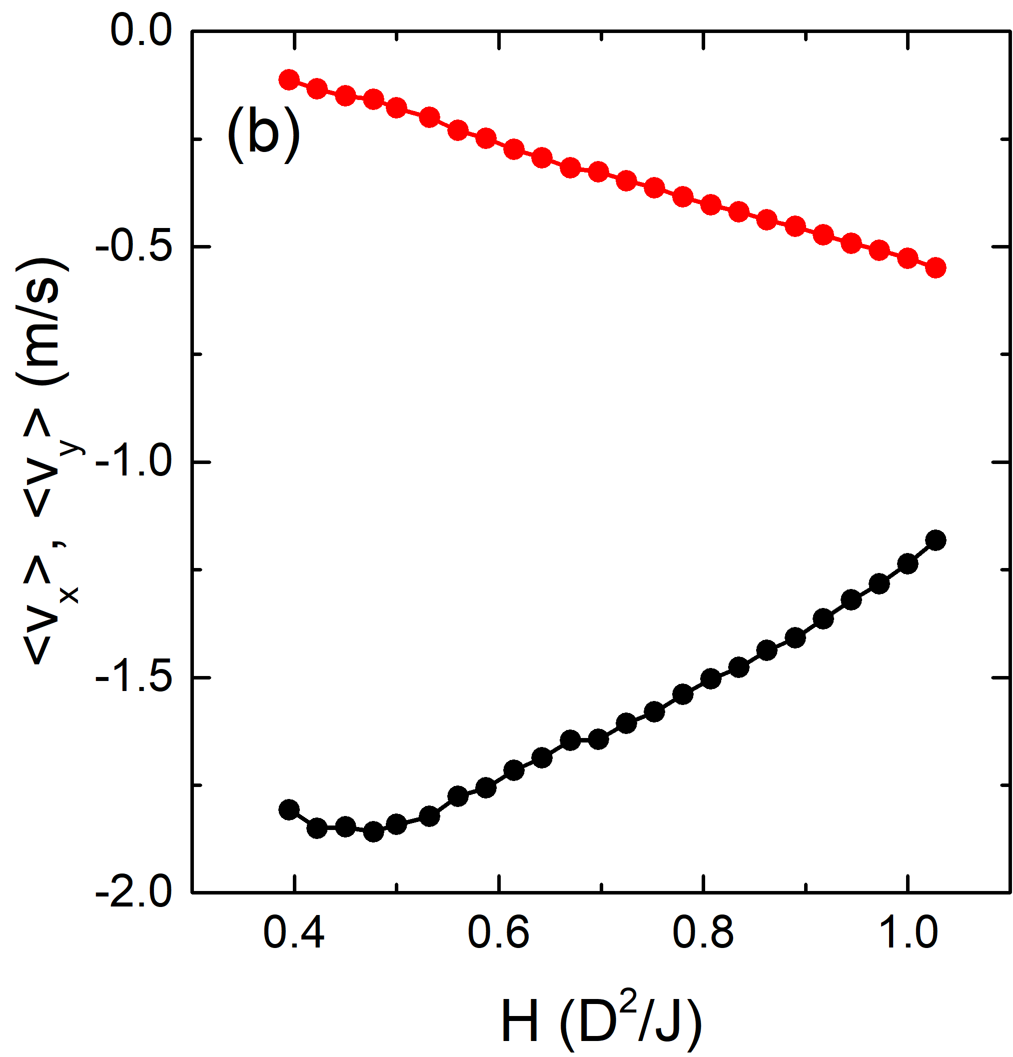
In figure 8(c) we plot the skyrmion velocities and averaged over all skyrmions during the entire simulation as a function of for dc and ac driving up to the critical annihilation currents. For both types of driving, since the skyrmions are simply being compressed in the direction, while increases monotonically in magnitude with increasing . The dc driven system exhibits much larger values of than the ac driven system.
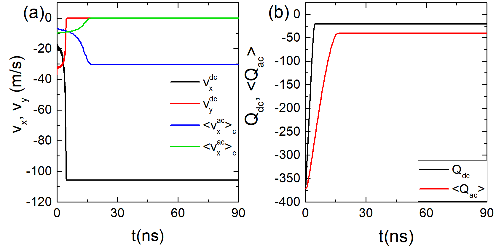
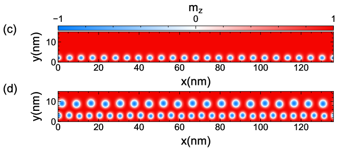
Figure 8(d) shows the charges and at the stable time for ac and dc driving as a function of . For every value of , , meaning that for a given , the dc driven system always contains fewer and/or smaller skyrmions than the ac driven system. In addition, the annihilation process occurs faster under dc driving than under ac driving. There is a wider range of values where the skyrmions remain stable in the ac driven system; however, this stability comes with a velocity cost, since the skyrmions subjected to ac driving have lower values of . For a better visualization of the stability, in figure 9 we compare ac and dc driven systems with . Figure 9(a) shows the skyrmion velocities as a function of time and in figure 9(b) we plot the topological charge as a function of time. The ac driven system requires to reach a stable compression, while for the dc driven system stable compression is achieved in . Skyrmion annihilation occurs for in both the ac and dc driven systems; however, the ac driven system has a higher topological charge, or higher skyrmion density, in the stable compressed state. This is illustrated in figure 9(c,d), where the ac driven system contains two rows of skyrmions moving along the wall, while there is only one row of skyrmions along the wall in the dc driven system. Figure 9(a) shows that even though the ac driven system conserves a larger number of skyrmions, the average velocity is much reduced compared to the dc system. Skyrmion annihilation occurs as a result of the applied current pushing the skyrmions against the wall, combined with the force gradient from the skyrmions in the upper part of the sample, which have larger sizes due to the density gradient. As more and more of the skyrmions are annihilated, the pressure from skyrmions in the upper part of the sample vanishes and eventually only the spin current pressure is available for annihilating the last row of skyrmions.
In possible applications where skyrmions carry information, the difference in the response between ac and dc driving is important, since although a dc drive transports the skyrmions more rapidly, the annihilation risk is higher. The optimum setting would be to use ac driving with ; however, variation of other parameters such as ac frequency should also be considered.
6 Varying the skyrmion size with
We next consider the influence on the dynamics of the skyrmion size, which is controlled by the value of . In order to avoid annihilation and focus on the dynamics, we fix for the dc driven system and for the ac driven system.
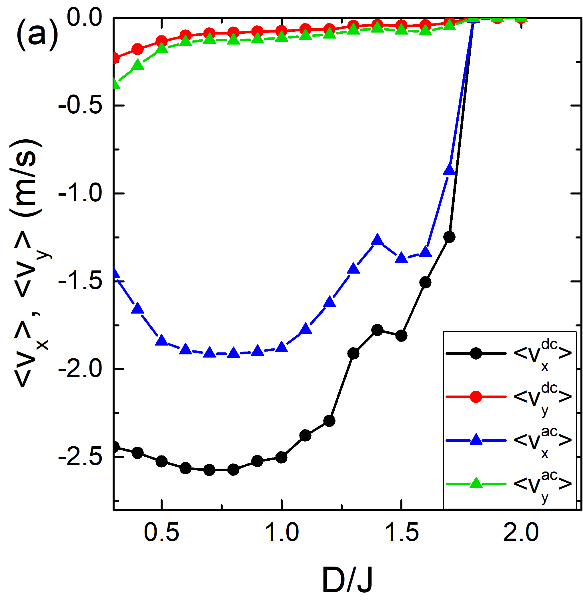
In figure 10 we show the time averaged skyrmion velocities and as a function of for both ac and dc driving. There is a clear nonmonotonic behavior of the velocities in the direction. When , for both types of driving the magnitude of the velocity increases with increasing while the magnitude of the velocity decreases. The largest direction velocity magnitude appears around , where and . The magnitude of the velocity decreases with increasing above , until for the motion in both the and directions for both ac and dc driving vanishes. When increases, the skyrmion size decreases, and since we are applying a constant field of , the skyrmion density increases as the skyrmion size is reduced. As the skyrmion gets smaller, it also becomes less susceptible to deformations and the gradient in skyrmion size from the top to the bottom of the sample diminishes. The skyrmion lattice itself also becomes more rigid as the skyrmions shrink, reducing its mobility under this compression geometry and resulting in the formation of a static compact lattice, as shown in figure 10(b). Comparing the skyrmions in figure 10(b) with those in figures 2 and 5, it is clear that the skyrmion size is much more uniform for the small skyrmions at .
7 The influence of the applied magnetic field
In this section we investigate how the applied magnetic field can influence the dynamics of the system by modifying the skyrmion density, size, and stability. For weaker fields the skyrmions are larger, while for higher fields the skyrmions become smaller and are reduced in number due to the strengthening of the ferromagnetic background. We fix and set for dc driving and for ac driving. We do not consider fields , since at these smaller fields, other topological textures become intermixed with the skyrmions during the initialization of the system.
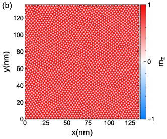
In figure 11 we plot the time averaged skyrmion velocities and for both dc and ac driving. In each case, we find a linear increase in with increasing due to the decrease in the size of the skyrmions. At high values of , the skyrmions become smaller but their density does not vary appreciably. As a result, the reduced size of the skyrmions produces a more dilute skyrmion lattice in which the skyrmions can more freely move. The vacant regions produce an increase in since the skyrmions must travel a greater distance in the direction to compress the lattice. The behavior of is non-monotonic as varies, and there is a value of magnetic field at which reaches its greatest magnitude. For dc driving, the velocity begins to decrease in magnitude for , while for ac driving, this decrease occurs for .
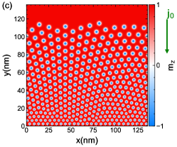
An illustration of the skyrmion sizes and the vacant spaces that appear in the skyrmion lattice under different magnetic fields appears in figure 12. As increases, the skyrmion size decreases, creating empty space and enabling a greater compression of the lattice along the direction. In figure 12(a) at , the skyrmions are still relatively large and there is a clear gradient in skyrmion size from top to bottom. At in figure 12(b), the skyrmions are reduced in size, while for in figure 12(c), the skyrmions have become very small, have lost their size gradient, and become tightly packed into the bottom part of the sample. The skyrmion sizes in figure 12(c) are similar to what is shown in figure 10(b), and there is no deformation of the skyrmions close to the wall since the skyrmions are small enough to have become rigid. Even without deformation of the skyrmions, we still find motion along the direction. This indicates that motion parallel to the wall results from a combination of both the skyrmion size gradient and the skyrmion density gradient. As more skyrmions are added to the sample, it becomes more difficult to compress and move the lattice, destroying the motion along the direction.
8 Particle Based Model
In order to better understand the role of the changing size of the skyrmions, we have also considered a Thiele equation approach in which the skyrmions are treated as point-like particles that have a repulsive interaction with each other and move under damping and a Magnus term, similar to what has been employed in previous studies [23, 24, 25, 26, 27, 28]. The equation of motion for a skyrmion is
| (7) |
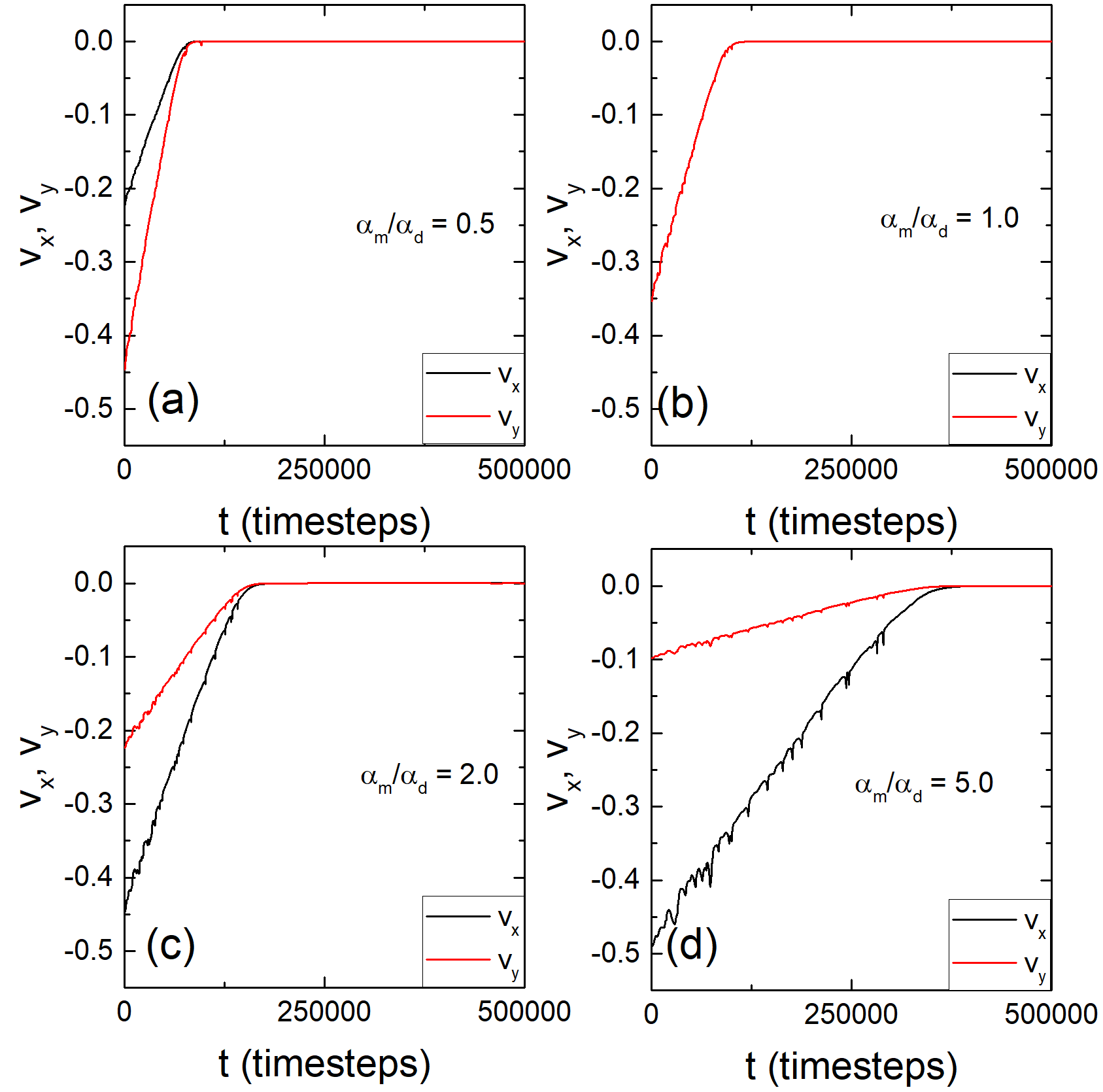
Here is the damping term, is the Magnus term, is the repulsive skyrmion-skyrmion interaction, is the interaction with the wall, and is the external driving force. The skyrmion-wall interaction is repulsive and is given by . The skyrmion-skyrmion interaction is also repulsive and has the Bessel shape , where is the first order Bessel function. In this particle based model, there is no skyrmion annihilation and the skyrmions have no size variations or internal degrees of freedom. In figure 13 we plot the skyrmion velocities and versus time for a system containing 100 point-like skyrmions interacting with a wall under a dc drive at Magnus force to damping force ratios of and . In each case, the system exhibits transient skyrmion velocities that vanish over time. In the atomistic magnetic model limit, for high values of the skyrmions are small enough so that they also act like point-like particles, and the skyrmion velocities also drop rapidly to zero with time. Hence, the smaller skyrmions of the atomistic model can be sufficiently well represented using a particle-based skyrmion model.
9 Summary
We have investigated the dynamics and the formation of conformal crystals for skyrmion crystals being pushed against a wall under dc and rectified ac driving. For dc driving, the skyrmion lattice does not compress uniformly but forms a conformal crystal structure with a density gradient and characteristic arch-like structure similar to that found experimentally in magnetic particles under gravity and vortices in type-II superconductors being injected into a sample from one side. The conformal crystal is not perfect but contains topological and structural defects similar to those found for the vortices and magnetic particles. One difference is that in the skyrmion case there is a skyrmion size gradient, with smaller skyrmions located close to the wall and larger skyrmions located further from the wall. We also find that during compression, although skyrmion annihilation is possible, there is an increase in the transverse velocity due to the Magnus force-induced creation of flows perpendicular to the pressure gradient direction. Under rectified ac driving with two states, a relaxation and a compression cycle, the rate of skyrmion annihilation is reduced but there is still a net dc motion transverse to the wall as a result of a skyrmion Magnus ratchet effect. Under dc driving, the skyrmions move as a rigid crystal, while for ac driving we observe a shear banding effect in which skyrmions near the wall move twice as fast as skyrmions far from the wall. Upon varying the magnitude of the external drive, we find a critical spin current above which all the skyrmions in the sample are annihilated, but below which the skyrmions can form a stable crystal translating along the direction. To modify the skyrmion size we vary the ratio and find that transverse flow occurs only for larger skyrmions with . The smaller skyrmions are more rigid, destroying the size gradient and consequently the transverse motion. We compare our results to those obtained in a particle-based model, and show that the rigid skyrmions of the particle-based model undergo no transverse motion, in agreement with what we find for small skyrmions in the atomistic model. A gradient in skyrmion size is required to produce steady state transverse motion, which arises as the result of an effective gradient in the skyrmion Hall angle since smaller skyrmions have a higher intrinsic Hall angle. Our results are relevant for the construction of devices in which skyrmions interact with magnetic walls, domain walls, or other types of repulsive interfaces.
Acknowledgements
This work was supported by the US Department of Energy through the Los Alamos National Laboratory. Los Alamos National Laboratory is operated by Triad National Security, LLC, for the National Nuclear Security Administration of the U. S. Department of Energy (Contract No. 892333218NCA000001). J.C.B.S and N.P.V acknowledge funding from Fundação de Amparo à Pesquisa do Estado de São Paulo - FAPESP (Grants 2021/04941-0 and 2017/20976-3 respectively).
References
References
- [1] Mühlbauer S, Binz B, Jonietz F, Pfleiderer C, Rosch A, Neubauer A, Georgii R and Böni P 2009 Science 323 915–919
- [2] Yu X Z, Onose Y, Kanazawa N, Park J H, Han J H, Matsui Y, Nagaosa N and Tokura Y 2010 Nature 465 901–904
- [3] Nagaosa N and Tokura Y 2013 Nature Nanotechnol. 8 899–911
- [4] Everschor-Sitte K, Masell J, Reeve R M and Kläui M 2018 Journal of Applied Physics 124 240901
- [5] Fert A, Reyren N and Cros V 2017 Nature Rev. Mater. 2 1–15
- [6] Iwasaki J, Mochizuki M and Nagaosa N 2013 Nature Commun. 4 1463
- [7] Pfleiderer C 2011 Nature Physics 7 673–674
- [8] Wiesendanger R 2016 Nature Reviews Materials 1 1–11
- [9] Fert A, Cros V and Sampaio J 2013 Nature Nanotechnol. 8 152–156
- [10] Zhang X, Ezawa M and Zhou Y 2015 Scientific Reports 5 9400
- [11] Luo S, Song M, Li X, Zhang Y, Hong J, Yang X, Zou X, Xu N and You L 2018 Nano Letters 18 1180–1184
- [12] Kang W, Huang Y, Zhang X, Zhou Y and Zhao W 2016 Proceedings of the IEEE 104 2040–2061
- [13] Reichhardt C and Reichhardt C J O 2016 Reports on Progress in Physics 80 026501
- [14] Litzius K, Lemesh I, Krüger B, Bassirian P, Caretta L, Richter K, Büttner F, Sato K, Tretiakov O A, Förster J, Reeve R M, Weigand M, Bykova I, Stoll H, Schütz G, Beach G S D and Kläui M 2017 Nature Phys. 13 170–175
- [15] Jiang W, Zhang X, Yu G, Zhang W, Wang X, Jungfleisch M B, Pearson J E, Cheng X, Heinonen O, Wang K L, Zhou Y, Hoffmann A and te Velthuis S G E 2017 Nature Phys. 13 162–169
- [16] Lin S Z, Reichhardt C, Batista C D and Saxena A 2013 Physical Review Letters 110 207202
- [17] Lin S Z, Reichhardt C, Batista C D and Saxena A 2013 Physical Review B 87 214419
- [18] Zeissler K, Finizio S, Barton C, Huxtable A J, Massey J, Raabe J, Sadovnikov A V, Nikitov S A, Brearton R, Hesjedal T, van der Laan G, Rosamond M C, Linfield E H, Burnell G and Marrows C H 2020 Nature Commun. 11 428
- [19] Brearton R, Turnbull L A, Verezhak J a T, Balakrishnan G, Hatton P D, van der Laan G and Hesjedal T 2021 Nature Communications 12 2723
- [20] Reichhardt C, Ray D and Reichhardt C J O 2015 Physical Review B 91 104426
- [21] Reichhardt C, Ray D and Reichhardt C J O 2018 Physical Review B 98 134418
- [22] Feilhauer J, Saha S, Tobik J, Zelent M, Heyderman L J and Mruczkiewicz M 2020 Physical Review B 102 184425
- [23] Vizarim N P, Reichhardt C J O, Venegas P A and Reichhardt C 2020 J. Phys. Commun. 4 085001
- [24] Vizarim N P, Reichhardt C J O, Venegas P A and Reichhardt C 2020 The European Physical Journal B 93 112
- [25] Vizarim N P, Reichhardt C, Reichhardt C J O and Venegas P A 2020 New Journal of Physics 22 053025
- [26] Vizarim N P, Reichhardt C, Venegas P A and Reichhardt C J O 2020 Physical Review B 102 104413
- [27] Vizarim N P, Souza J C B, Reichhardt C J O, Reichhardt C, Milošević M V and Venegas P A 2022 Physical Review B 105 224409
- [28] Reichhardt C and Reichhardt C J O 2022 Physical Review B 105 214437
- [29] Reichhardt C, Ray D and Reichhardt C J O 2015 New J. Phys. 17 073034
- [30] Göbel B and Mertig I 2021 Sci. Rep. 11 3020
- [31] Souza J C B, Vizarim N P, Reichhardt C J O, Reichhardt C and Venegas P A 2021 Phys. Rev. B 104 054434
- [32] Chen W, Liu L, Ji Y and Zheng Y 2019 Physical Review B 99 064431
- [33] Ma X, Reichhardt C J O and Reichhardt C 2017 Phys. Rev. B 95 104401
- [34] Chen W, Liu L and Zheng Y 2020 Physical Review Applied 14 064014
- [35] Vizarim N P, Reichhardt C, Venegas P A and Reichhardt C J O 2021 J. Mag. Mag. Mater. 528 167710
- [36] Zhang C L, Wang J N, Song C K, Mehmood N, Zeng Z Z, Ma Y X, Wang J B and Liu Q F 2022 Rare Metals 41 865–870
- [37] Yanes R, Garcia-Sanchez F, Luis R F, Martinez E, Raposo V, Torres L and Lopez-Diaz L 2019 Applied Physics Letters 115 132401
- [38] Zhang S L, Wang W W, Burn D M, Peng H, Berger H, Bauer A, Pfleiderer C, van der Laan G and Hesjedal T 2018 Nature Communications 9 2115
- [39] Everschor K, Garst M, Binz B, Jonietz F, Mühlbauer S, Pfleiderer C and Rosch A 2012 Physical Review B 86 054432
- [40] Kong L and Zang J 2013 Physical Review Letters 111 067203
- [41] Purnama I, Gan W L, Wong D W and Lew W S 2015 Scientific Reports 5 10620
- [42] Menezes R M, Neto J F S, Silva C C d S and Milošević M V 2019 Physical Review B 100 014431
- [43] Rothen F, Pieranski P, Rivier N and Joyet A 1993 European Journal of Physics 14 227
- [44] Rothen F and Pierański P 1996 Physical Review E 53 2828–2842
- [45] Ray D, Olson Reichhardt C J, Jankó B and Reichhardt C 2013 Physical Review Letters 110 267001
- [46] Wang Y L, Latimer M L, Xiao Z L, Divan R, Ocola L E, Crabtree G W and Kwok W K 2013 Physical Review B 87 220501
- [47] Menezes R M and Silva C C d S 2017 Scientific Reports 7 12766
- [48] Menezes R M, Sardella E, Cabral L R E and Silva C C d S 2019 Journal of Physics: Condensed Matter 31 175402
- [49] Meng Q and Grason G M 2021 Physical Review E 104 034614
- [50] Zhang X, Xia J and Liu X 2022 Physical Review B 105 184402
- [51] Evans R F L 2018 Atomistic Spin Dynamics Handbook of Materials Modeling: Applications: Current and Emerging Materials ed Andreoni W and Yip S (Springer International Publishing) pp 1–23
- [52] Iwasaki J, Mochizuki M and Nagaosa N 2013 Nature Nanotechnology 8 742–747
- [53] Seki S and Mochizuki M 2016 Skyrmions in Magnetic Materials SpringerBriefs in Physics (Springer International Publishing)
- [54] Zhang X, Zhou Y and Ezawa M 2016 Scientific Reports 6 24795
- [55] Stosic D, Ludermir T B and Milošević M V 2017 Physical Review B 96 214403
- [56] Zang J, Mostovoy M, Han J H and Nagaosa N 2011 Physical Review Letters 107 136804
- [57] Kim J V and Mulkers J 2020 IOP SciNotes 1 025211
- [58] Schulz T, Ritz R, Bauer A, Halder M, Wagner M, Franz C, Pfleiderer C, Everschor K, Garst M and Rosch A 2012 Nature Phys. 8 301–304
- [59] Banerjee D, Souslov A, Abanov A G and Vitelli V 2017 Nature Communications 8 1573
- [60] Iwasaki J, Koshibae W and Nagaosa N 2014 Nano Letters 14 4432–4437
- [61] Xing X, Åkerman J and Zhou Y 2020 Physical Review B 101 214432
- [62] Souza J C B, Vizarim N P, Reichhardt C J O, Reichhardt C and Venegas P A 2022 Clogging, diode and collective effects of skyrmions in funnel geometries
- [63] Sugimoto S, Koshibae W, Kasai S, Ogawa N, Takahashi Y, Nagaosa N and Tokura Y 2020 Scientific Reports 10 1009