Creation of single vacancies in hBN with electron irradiation
Abstract
Understanding electron irradiation effects is vital not only for reliable characterization of materials using transmission electron microscopy, but increasingly also for the controlled manipulation of two-dimensional materials. Knock-on displacements due to elastic electron backscattering are theoretically straightforward to model, and appear to correctly describe damage in pristine graphene. For semiconducting MoS2, some experimental and theoretical progress has been recently made, indicating that a combination of elastic and inelastic effects appears to be needed to explain experiments. For insulating hexagonal boron nitride (hBN), however, much less is currently known. We measure the displacement cross sections of suspended monolayer hBN using aberration-corrected scanning transmission electron microscopy in near ultra-high vacuum at primary beam energies between 50 and 90 keV. We find damage rates below 80 keV up to three orders of magnitude lower than previously measured at hBN edges under comparatively poorer residual vacuum conditions where chemical etching appears to have been the dominant damage mechanism. Notably, we are now able to show that it is possible to create single vacancies in hBN using electron irradiation, and resolve that boron are almost twice as likely as nitrogen to be ejected below 80 keV. Moreover, any damage at such low energies cannot be explained by pure elastic knock-on, even when accounting for vibrations of the atoms. We thus develop a theoretical description that accounts for a lowering of the displacement threshold energy due to valence ionization resulting from inelastic scattering of probe electrons, and model this using charge-constrained density functional theory molecular dynamics. Although significant reductions in threshold energies are found depending on the constrained charge, quantitative predictions for specific ionization states are currently not possible from first principles. Nonetheless, our findings show the potential for defect-engineering of hBN at the level of single vacancies using electron irradiation.
University of Vienna] University of Vienna, Faculty of Physics, Boltzmanngasse 5, 1090 Vienna, Austria
Keywords: hBN, vacancies, electron irradiation, STEM, ultra-high vacuum
Transmission electron microscopy (TEM) is a powerful probe of the atomic structure of materials, and is particularly well suited to directly reveal any defects in the lattice of the specimen. The pioneering work of Crewe 1 marks the beginning of practical scanning transmission electron microscopy (STEM). From then on, the scanning probe mode was developed as a technique complementary to broad-beam illumination. Due to annular dark-field detection, yielding direct atomic-number contrast, STEM is particularly useful for imaging materials with a mixed elemental composition.
Two-dimensional (2D) materials, a structure family introduced by Novoselov and Geim exfoliating single-layer graphene from graphite 2, provide due to their thinness ideal samples for TEM techniques, especially for atomically resolved quantification of irradiation effects 3. This is important because the electron beam can cause changes in the structure of a specimen. Radiation damage in the TEM can be divided into knock-on damage, radiolysis and chemical etching 4. The exact mechanism of radiation damage in a specific material is of practical interest as it determines what options are available for minimizing it.
Ballistic displacements (so called knock-on damage) are caused by (quasi-)elastic scattering, where the electron directly transfers momentum to an atomic nucleus. If the resulting kinetic energy of the atom exceeds the displacement threshold energy (), the atom is ejected from its lattice position 5, 6. When the knock-on mechanism is predominant, reducing the TEM acceleration voltage will suppress damage 7. This process is well understood, especially in graphene 7, 8, although recent studies have suggested that dynamics at its impurity sites cannot be explained by purely elastic effects 9, 10.
While radiolysis – the direct breaking of bonds due to ionization of valence electrons – is assumed to be predominant in insulators, in conducting materials it is largely quenched due to rapid neutralization. In inorganic solids, both knock-on and ionization effects can take place, sometimes simultaneously. If the damaging effects arise from beam heating or from electrostatic charging of an insulating specimen, reducing the incident beam current can be helpful 11. To understand the interaction of electrons with different materials, especially semiconductors or insulators where the knock-on mechanism is not the only relevant damage mechanism, a theoretical model describing the process is needed.
For MoS2, recent work has taken the first steps towards quantitative understanding, suggesting excitation-assisted knock-on damage to be the dominant mechanism at electron energies below 80 keV 12, 13. Kretschmer et al. proposed a way to quantify both effects in a combined theoretical framework 14, and the model was further improved by Speckmann et al., removing the ambiguity in model parameters 15. Additionally, Yoshimura et al. created a quantum theory of electronic excitation and sputtering and applied it to both MoS2 and hBN 16. However, the experimental data on hBN they had access to left much to be desired, and thus further developments urgently need accurate quantitative measurements. In particular, the residual vacuum can cause damage to the specimen due to beam-induced chemical etching 17. The electron beam dissociates gas molecules, which can then react with atoms of the lattice. This process is responsible for the growth of pores in graphene 18, and almost certainly also in hBN – which is how the only available quantitative data was collected 19.
Defects in hBN are especially interesting for quantum light emission, as its color centers display bright 20 and thermally stable 21 single-photon emission across a wide spectral range 22, 23, 24. As such, hBN has potential as a useful platform for quantum computation, information networks and sensors 25. Irradiation with lasers 26, ions 27, neutrons 28 or electrons 29, 30 have emerged as viable techniques for creating such color centers, and although their exact atomic configuration has been unclear, point defects are certainly involved 31, 22, 32, 30, 33. However, considering the rapid damage and creation of pores under typical TEM conditions 6, 19, it has not been clear whether single vacancies can be controllably created.
1 Results and Discussion
We carried out measurements in ultra-high vacuum (UHV), which suppresses unwanted chemical etching and allows us to obtain separate cross sections for individual B and N at atomic resolution. Chemical etching occurs already at a typical residual vacuum pressure of 10-7 mbar 17, which can even change the dominant termination of pore edges in electron-irradiated graphene 18. Indeed, the cross sections we measure are up to three orders of magnitude lower than what was reported for atoms at pore edges 6, 19, suggesting previous experiments have been dominated by chemical etching and showing that single vacancies can indeed be created by electron irradiation at intermediate energies.
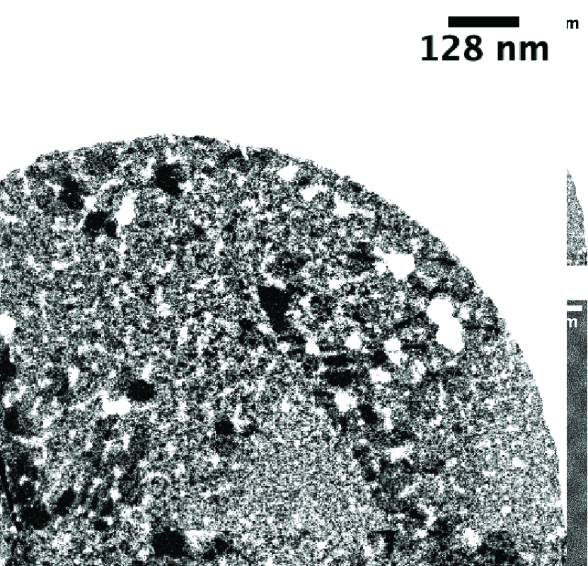
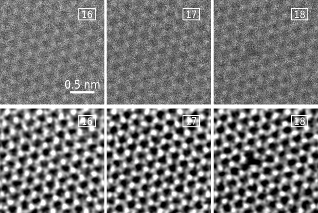
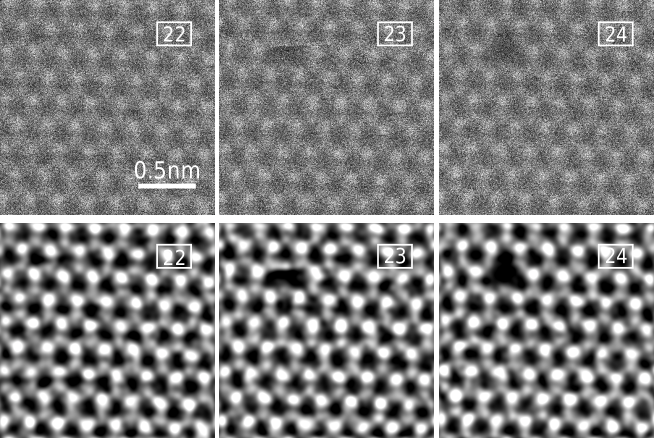
Samples were prepared using commercial hBN grown by chemical vapor deposition following the procedure of Ref. 34 (see Methods), containing clean areas up to 100 nm in size. An overview at different length scales is provided in Fig. 1. Exemplary STEM medium-angle annular dark-field image series recorded at an energy of 55 keV are displayed in Figs. 2 and 3, which show both raw data as well as double-Gaussian filtered images 35. Each frame has 512512 pixels for a field of view of typically 22 nm2 and a scanning time of roughly 0.26 s. While scanning even faster would be beneficial, we found that this would have degraded the signal to noise ratio too much for reliable analysis.
Only cases where we could unambiguously identify the first ejected atom were included in the analysis. Cases where two separated vacancies of the same element were present in the first defected frame were counted as only a single vacancy, since the creation of the first could have facilitated the second. Just twice in all our data were two separated N and B atoms missing in the first defective frame, illustrating a high probability to create single vacancies.
To identify the number of frames without a defect and the position where the first vacancy occurred, a machine-learning algorithm based on a convolutional neural network was used to assist human analysis (see Methods and Supporting Information). The experimental displacement cross section 5, 36, 7, 3 can be derived from the electron dose , which consist of dose rate multiplied by time until the defect (detailed calculation can be found in the Supporting Information). It corresponds, following Poisson statistics, to the expectation value of the dose for the distribution arising from a large number of repeated measurements.
Dose rates were evaluated by estimating the beam current impinging on the sample via continuous measurement of the current falling on the virtual objective aperture of the microscope, which is saved with the image metadata. This current in turn was calibrated against the beam current measured at the drift tube of the electron energy-loss spectrometer. While typically the beam current is measured only occasionally, we recently found this may lead to significant errors in the estimated doses, and thus have used here the statistical measurements described in Ref. 15.
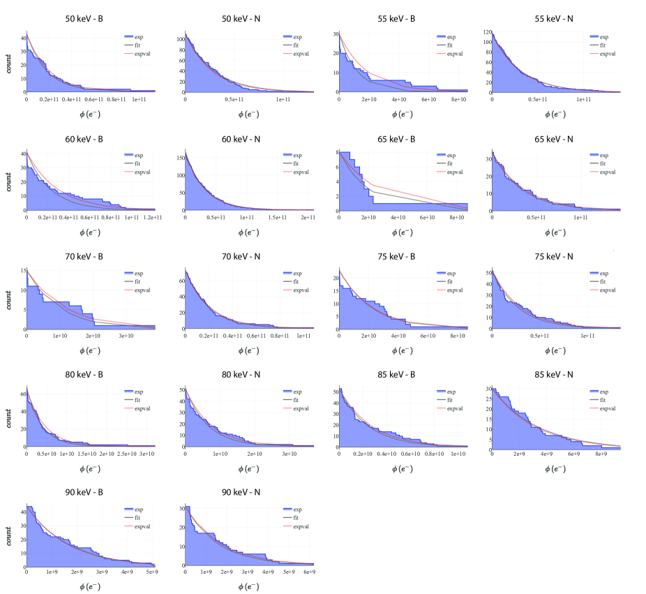
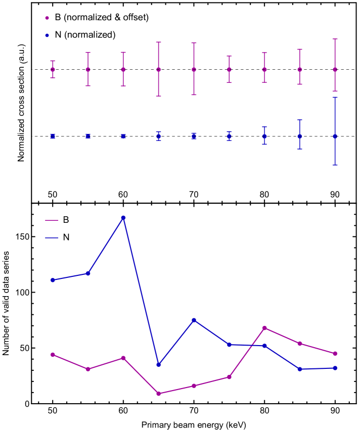
The displacement cross section describes the probability of an energetic electron scattering from an atomically thin sample to lead to a displacement of one of its atoms, calculated as the inverse of the Poisson expectation value multiplied by the material-specific areal density (see Supporting Information for more detail). To obtain accurate values of such a stochastic process, measurements of pristine areas need to be repeated until sufficient statistics are collected. Our analysis includes 664 valid series for N and 337 for B (Supporting Fig. S2 displays histograms of the data).
1.1 Simulation of ionization-assisted displacement thresholds
To study the role that valence ionization might play in the knock-on damage process, we performed density functional theory molecular dynamics (DFT/MD) simulations of the ejection of either N or B atoms from hBN following our established methodology 37, 8 (see Methods for more detail). In addition to ground-state calculations previously reported for hBN 6, we now use constrained DFT (cDFT) to confine a point charge on the ejecting atom to quantify its effect on the displacement threshold energy. We note that this description is not entirely realistic, as the confining potential has no direct physical interpretation, and it is enforced for the full duration of the simulation (i.e. there is no charge neutralization). Accurately describing dynamics with a localized valence hole in periodic supercell is a difficult challenge, and thus this approach should be considered as a pragmatic if imperfect approximation.
In earlier work, Kotakoski et al. 6 calculated the displacement thresholds for B and N atoms in the pristine structure and at different vacancy edges in various total charge states. For pristine structures in the ground state, they obtained eV and eV, somewhat different than our values of eV and eV. We recently noticed that the specific value of Fermi smearing used in GPAW seems to have an influence of about this magnitude on the absolute threshold energy values 10, though also the difference between the two elements seems also to be slightly different (3.7 eV vs. 2.1 eV). Nonetheless, the two calculations are in general agreement.
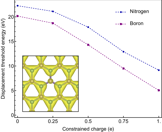
For a full positive constrained elementary charge (corresponding to a missing electron), we find that the displacement threshold for N drops from 22.25 eV to 9.15 eV (59%), while that for B drops from 20.15 eV to 5.05 eV (75%). Since it is likely that even in an insulating material such as hBN, some part of the ionized charge is neutralized during the roughly 100 fs it takes for the impacted atom to fully displace, we also considered partial charges to study the systematic behavior of the threshold energy. These results are shown in Fig. 4: after a slighter reduction for the 0.25 hole, the values drop roughly linearly with a slope of -16.3 eV/e for N and -18.2 eV/e for B.
1.2 Theoretical cross section with ionization
From the displacement threshold energy one can estimate the displacement cross section under known electron-beam conditions using the McKinley-Feshbach formalism 38 for Coulombic scattering of relativistic electrons 39. The corresponding total elastic displacement cross section 40, 36, with the velocities of the atoms accounted for using phonon modeling 8 (as described in the Methods), can be written as
| (1) |
where is the maximum transmitted energy at out-of-plane velocity , is the atomic number, the elementary charge, the electric constant in vacuum, the electron rest mass, and the fine-structure constant. The relativistic Lorentz factor is , and depends on the primary beam energy as
| (2) |
Previously only the ground-state dynamics were considered. However, beam-induced excitation may reduce the bonding energy of the atoms in the lattice, thus reducing the threshold energy. While the displacement caused by an elastic scattering process (also known as a knock-on displacement) is well understood and theoretically described, the role of inelastic electron-electron scattering still remains unclear. A classical theoretical model was derived by Bethe 41, later on complemented relativistically by Møller 42. A modification of Bethe’s theoretical formula by using impact parameter and substitutions to fit experiments was done by Williams 43, which is the source of the inelastic scattering cross section reprinted in Williams & Carter 44. However, despite being well known, that formula was provided in CGS units and the definition of the included velocity term was not explicitly given. It is therefore worth reprinting it here, with some modification.
In SI units, the ionization cross section for shell is (see Supporting Information)
| (3) |
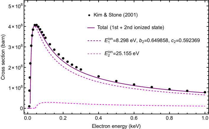
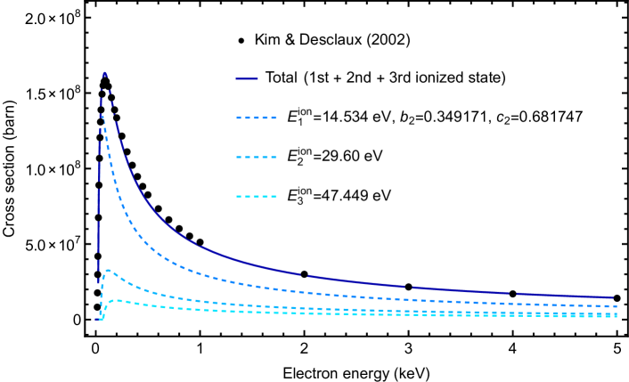
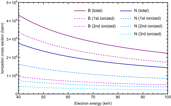
where is the number of electrons in the subshell that is ionized, and are a priori unknown constants for that shell, and is in our treatment the th ionization energy. For a given electron shell and known ionization energies, measured atomic cross section data can be fitted to obtain the constants. As this data is available for low primary beam energies (up to 1 keV for B 45 and 5 keV for N46), care must be made to fit the highest-energy data points as well as possible so that the slope extending to our experimental energy range is correct (see Supporting Information for detail).
As will be discussed in the next section, it turns out that to be able to fit experimental hBN data, we needed to include two ionized states for boron (Supporting Fig. S5) and three for nitrogen (Supporting Fig. S6). The calculated ionization cross sections, extrapolated to our experimentally relevant primary beam energies, are shown in Supporting Fig. S7. The cross section values are on the order of barn and show the characteristic dependence, though it should be noted that their ratio remains almost constant at 0.68–0.69 across the TEM-relevant range of energies (20–100 keV). However, as we will see when trying to describe the experimental displacement data for hBN, we had to modify the probabilities of each ionized state to obtain a good match.
1.3 Fitting experimental cross sections
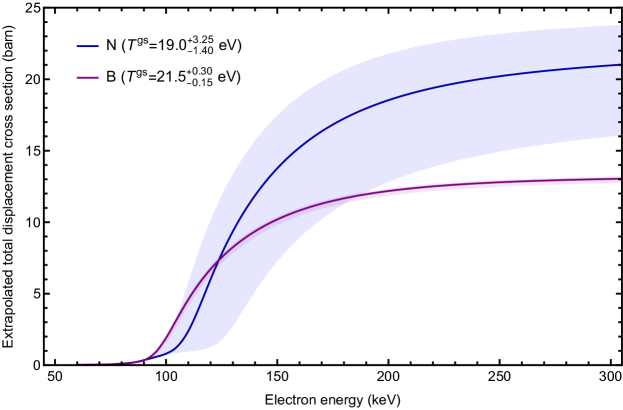
In hBN the mass difference between the two constituent elements is more than 20%. For N, we only need to consider the stable 14N isotope. However, boron has two abundant stable isotopes with a significant relative mass difference, and thus we need to consider separately 10B and 11B with ca. 20 atom-% and 80 atom-% where the masses are 10.01 u and 11.01 u. Due to the greater mass of nitrogen, elastic energy transfers from primary beam electrons at our experimental energies are suppressed at displacement threshold energies below 19 eV, significantly below what DFT predict (Fig. 6), which means that the displacement of nitrogen from the ground state cannot happen at energies up to 90 keV.
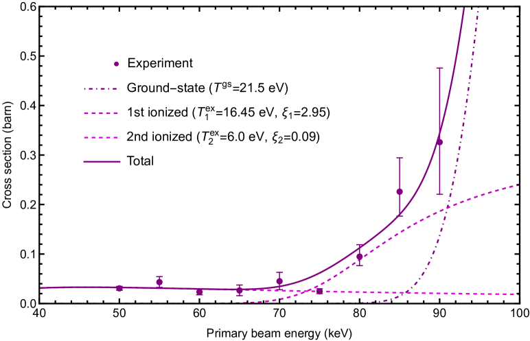
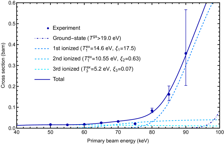
Figures 5 and 6 show a fitting of the experimental data with our theoretical model that combines the earlier mentioned elastic and inelastic scattering processes. (The experimental points at 75 keV for both elements were excluded from the fits as outliers, and we suspect that the experimental current at that energy does not match the measured calibrations.) The total displacement cross section is calculated as a additive combination of the ground and excited states multiplied by the corresponding Bethe cross sections and the areal density
| (4) |
where indexes the ionization state (up to = 2 for B and 3 for N) and is a parameter accounting for inaccuracies in the ionization cross sections as well as finite lifetimes of the excited states. As the material consists of two elements, two separate analyses were conducted, with the above-mentioned isotope-weighted average used for boron.
It is clear from the plots that the theoretically predicted ground-state threshold energies cannot alone describe the observed cross section values – indeed, for nitrogen no damage would be expected up to 90 keV even if the ground-state threshold energy was as low as 19 eV – whereas the combined model does provide a good fit with the data. However, we did have to significantly increase the atomic ionization cross sections for the first ionized state: 2.92 times for boron and as much as 18.4 times for nitrogen. Only values smaller than 1 can be explained by a finite lifetime of the excitation 16, 15.
1.4 Discussion
We must note that the model described above is simplified in two important ways. First, the ionization energies used for the Bethe cross section in Eq. 3 are tabulated for sequential ionization, ie. the removal of further electrons from an already ionized atom, which is unlikely to be the case experimentally for hBN (and would require the multiplication of ionization probabilities). We consider the model as an approximate description of the more likely experimental situation, namely multiple ionization by the same electron. Second, the probability of being in an ionized state should be subtracted from the ground-state process, as was done in Ref. 15. However, in our case this is not possible, as allowing to take values above 1 – indicating that the fitted atomic ionization cross sections underestimate the probability of ionization in hBN or that the process cannot correctly be described using this model – would mean that probabilities do not sum correctly. We have therefore neglected this correction, which would slightly lower the fitted ground-state threshold energies.
Using ionization cross-section data measured for atoms is clearly not ideal for describing a periodic solid with significant ionic character. Measurements on more closely related molecules such as borazine, or even better, hexaborane, might provide an improved reference model. Even better would be direct measurements on hBN itself at the experimentally relevant TEM energies, but this is clearly not feasible using crossed beams of electrons and fast atoms or molecules which are the standard method to measure impact ionization cross sections 47. Nonetheless, due to the relatively weak dependence of the extrapolated high-energy tail of the cross sections on the details of the fitting of the low-energy data, we agree with Kretschmer et al. 14 that this approach can provide a useful approximation.
The range of fitted excited-state thresholds falls within the simulated cDFT/MD values, but it is difficult to predict them for specific ionization states from first principles. Constrained DFT as a starting point for Ehrenfest dynamics is not feasible due to the artificial nature of the constraining potential: time-dependent dynamics without the constraint lead to rapid neutralization of the charge on a timescale much shorter than the time to displace an atom. Thus, further theory development based on the precise cross section values reported here will be needed for a correct first-principles description of hBN irradiation damage.
A recent study has suggested that nitrogen vacancies are the active color center in hBN 30. Our precise experimental measurements seem to indicate that it is quite challenging to exclusively create N vacancies, as the cross section for knocking out B atoms is higher across the range of studied energies. Nonetheless, even parallel-beam irradiation at 200 keV can apparently controllably create optically active regions in hBN 30. This may be explainable by the extrapolation of our cross sections to higher primary beam energies: at 200 keV, due to its lower threshold energies and the decreased importance of their mass difference, the ejection of N becomes more likely than that of B (Supporting Fig. S8). This could result in a greater number of N vacancies at a fixed irradiation dose. Additional data at primary beam energies higher than 90 keV would be helpful to further reduce the related uncertainties, but the rapidly increasing damage cross section means that even at 90 keV, in many data series larger defects appear already as the very first defect, making it impossible to assign the element to the first ejection and thus to obtain reliable estimates.
Now that it is clear that hBN is remarkably radiation resistant at primary beam energies below 80 keV, the creation of color centers could potentially be greatly optimized by site-selective irradiation using a focused STEM electron probe 48 coupled with low-dose imaging and automation enabled by machine learning 49.
2 Conclusion
Despite its insulating nature, monolayer hexagonal boron nitride is surprisingly stable under electron irradiation when chemical etching can be prevented. Single boron and nitrogen vacancies can be created at intermediate electron energies, although boron are twice as likely to be ejected due to its lower mass. However, we predict that at energies of 200 keV and above, nitrogen in turn becomes easier to eject. Providing reliable experimental measurements to develop theoretical models can lead to a better understanding of ionization damage in non-conducting materials more broadly, where a combination of inelastic and elastic scattering appears to be active. Further, point defects in hBN are of great current interest due to their single-photon emission properties, and it may be possible to use electron irradiation to purposefully create them. New opportunities for atomically precise manipulation, until now demonstrated for dopant atoms in graphene and in bulk silicon, may also be uncovered.
3 Methods
3.1 Sample preparation
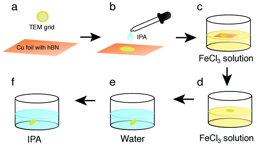
Commercial monolayer hBN synthesized with chemical vapor deposition 50 on copper foil purchased from Graphene Supermarket (CVD hBN on copper foil) was transferred onto a conventional Au Quantifoil TEM grid (R 1.2/1.3) (Supporting Figure S1a). To attach the TEM grids onto hBN, a drop of isopropanol (IPA) was put on top of the already placed grid (Supporting Figure S1b). For a successful transfer, uniform adhesion between the substrate and the TEM grids is necessary. To etch away the copper foil, we used an 10% iron(III)-chloride(FeCl3) acid solution (Supporting Figure S1c). The sample was introduced to vacuum and baked overnight at ca. 150°C before measurements were conducted. Between measurements, the sample was stored in the CANVAS ultra-high vacuum system 51.
3.2 Scanning transmission electron microscopy and analysis
STEM measurements were performed with an aberration-corrected Nion UltraSTEM100 at primary beam energies ranging from 50 to 90 keV. Image series were recorded using a medium-angle annular dark field (MAADF) detector with a collection angle of 80–200 mrad. The base pressure at the sample was below 10-9 mbar, suppressing any chemical etching 17.
A machine-learning algorithm based on a convolutional neural network trained using simulated images 52 was used to detect the position of the first occurring defect in each recorded image series. The intensity difference between the N and B sublattices was also used to determine which element was ejected, and the analysis results were verified by manual inspection (see Supporting Information for detail).
3.3 Density functional theory molecular dynamics
To perform the simulations, we used the Atomic Simulation Environment 53 for Velocity-Verlet dynamics with a timestep of 0.3 fs on a 771 graphene supercell, with forces from a GPAW 54 calculator with the PBE functional 55, a localized dzp basis set, a 551 Monkhorst-Pack -point grid, and a Fermi-Dirac smearing of 0.025 eV.
The GPAW implementation of cDFT imposes a localized constraining potential via an atom-centered Gaussian function 56, whose weight is iteratively optimized to achieve the desired charge on the atom as assessed by Hirshfeld partitioning 57. For the ground state, we considered both spin-paired and spin-polarized calculations, whereas the charge-constraint was always imposed on one spin channel. We also simulated 661 and 551 supercells, and confirmed that the calculated threshold energies are converged within 0.1 eV.
3.4 Phonon density of states
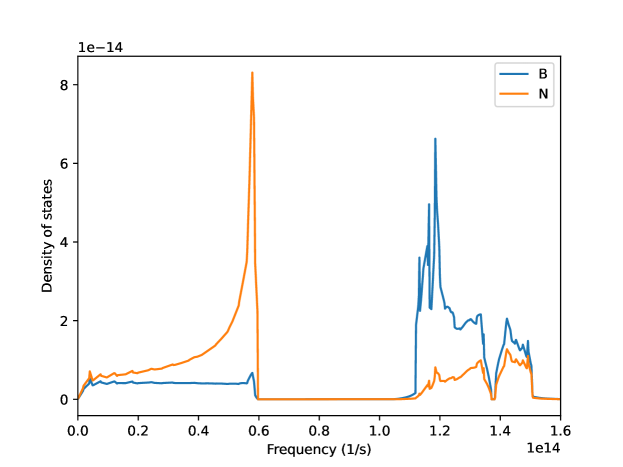
Phonon calculations were performed using density functional perturbation theory (DFPT) 58, 59 as implemented in the ABINIT code 60. The lattice structure was first optimized down to an energy difference of 10-10 Ha with a k-point mesh of 20201 and an energy cut-off of 55 Ha. Exchange and correlation were described using the local density approximation and Troullier–Martins norm-conserving pseudo-potential 61.
For calculating the Hessian and dynamic matrix, the ground-state wave functions were converged to within 10-18 Ha2 with a k-point mesh of 40401. Phonon density of states (DOS) was interpolated using the Gaussian method with a smearing of 6.510-5 Ha, and assigned to the B and N sublattice to estimate their out-of-plane mean-square velocities as described in Ref. 8. The calculated phonon DOS is shown as Supporting Fig. S9.
4 Supporting Information
Supporting Information: Schematic illustration of sample preparation, detailed description of experimental cross section, histograms and numerical values of experimental data, description of machine-learning algorithm, detailed description of theoretical ionization cross section, fitting of atomic impact ionization data, extrapolated theoretical valence ionization cross sections for B and N, extrapolated total displacement cross sections for hBN, and plot of the phonon density of states (PDF; numerical data included also as comma-separated files). Calculations and fitting of the theoretical cross section models to the data (Wolfram Mathematica 13.1 notebook) can be accessed on the Wolfram Notebook Archive at \urlhttps://notebookarchive.org/2023-05-4lw178w. The raw experimental STEM datasets can be accessed on the University of Vienna institutional repository Phairda online at \urlhttps://doi.org/10.25365/phaidra.399.
T.A.B, J.M., M.R.A.M., A.I.C., A.P., and T.S. were supported by the European Research Council (ERC) under the European Union’s Horizon 2020 research and innovation programme (Grant agreement No. 756277-ATMEN). We gratefully acknowledge computational resources provided by the Vienna Scientific Cluster (VSC).
4.1 Sample preparation
4.2 Experimental displacement cross section
4.2.1 Dose until first defect
The electron dose is defined as the number of the electrons hitting the specimen. The dose rate (s-1) is defined by a beam current on the sample divided by the elementary charge
| (5) |
In the experimental setup the current can not be measured directly on the sample. From the metadata we know the virtual objective aperture (VOA) current and can calculate the current on the sample with the calibration constant and dark-current .
The time until the first defect occurred is the total number of pixels multiplied by the dwell time
| (6) |
We assume that our experimental data follows a Poisson process and therefore the cumulative doses are exponentially distributed, obtained by cumulating them in discrete bins, where the first bin contains the total number of all events (counts) and in the next bin, only events with doses higher than the bin width remain. The same procedure is repeated for the following bins until the last one. Histograms containing the cumulative event counts with respect to the dose bins are shown in Supporting Fig. S2.
This exponential fit-value is our expectation value for the dose for each set of experimental parameters, most importantly the primary beam energy . It is adapted from the probability density function
| (8) |
where is the irradiation dose.
Because both boron and nitrogen atoms can be displaced, but have different , they must be analyzed separately. Correspondingly, the doses until the first defect need to be added up separately for boron and nitrogen. Since we want to measure the knock-on cross sections of the pristine material, defects with two or more atoms missing, which do happen often especially at higher primary beam energies (at 90 keV, this was the case in the majority of the experimental data series), need to be omitted from the analysis. We have also omitted cases where defects occur at the edge of the frame, because it is not clear whether those are single vacancies.
4.2.2 Experimental displacement cross sections
The displacement cross sections of the experimental data at each primary beam energy were calculated via the expectation values of the dose as described in the previous section and the areal density of hBN as
| (9) |
The uncertainty of the experimental data was obtained by Gaussian error propagation, and the sum of uncertainty-weighted mean-squared errors was used for fitting the theoretical curves.
| B | N | |||||
|---|---|---|---|---|---|---|
| (keV) | (mb) | + | - | (mb) | + | - |
| 50 | 28.5 | 4.0 | 3.8 | 17.2 | 0.5 | 0.5 |
| 55 | 47.7 | 11.1 | 10.5 | 15.9 | 0.5 | 0.4 |
| 60 | 30.4 | 6.0 | 5.7 | 18.4 | 0.5 | 0.4 |
| 65 | 34.3 | 10.9 | 10.6 | 25.5 | 1.8 | 1.6 |
| 70 | 63.3 | 18.0 | 17.0 | 32.1 | 1.5 | 1.2 |
| 75 | 26.1 | 5.0 | 4.8 | 21.2 | 1.5 | 1.3 |
| 80 | 142.1 | 24.1 | 18.2 | 83.8 | 12.0 | 9.9 |
| 85 | 235.1 | 68.5 | 49.5 | 161.7 | 40.1 | 30.8 |
| 90 | 321.5 | 149.8 | 106.5 | 357.7 | 209.0 | 153.6 |
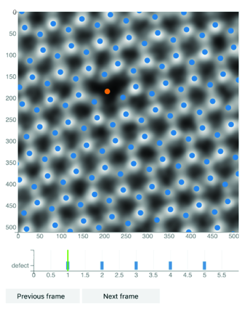
4.2.3 Machine-learning algorithm
To ease a manual analysis of the images, a more accurate computer-assisted way was developed. A machine-learning algorithm not only detects the position of first occurring defect but also can tell by the intensity difference which element has been ejected. Supporting Figure S4 shows an example of one recorded series with 512512 pixels. The image shows the second frame, below which is a plot of the series analysis where detected defects are indicated by blue bars. The green line indicates where the first defect has been detected, which is the second frame in this case. With the integrated Gaussian filter applied to the image here it is easier to identify the different atoms by their contrast, which makes it possible to cross check the result manually.
5 Ionization cross section
To derive a practical expression for the probability of impact ionization, we start from the relativistic Bethe inelastic scattering cross section for electron shell from Williams & Carter (Eq. 4.2 in Ref. 44):
| (10) |
where is the number of electrons in the ionized subshell, and , are constants for that shell, and is its critical ionization energy. Notably already is the relativistic rest mass (equal to 511 keV/c2).
Since valence ionization energies are much smaller than those of core electrons, one could expect that they dominate the cross section, at least at relatively modest energies. If that assumption holds, we can use the Bethe formula only for the outermost shell, whose occupation is just the valence of the element ( and for B and N, respectively). Thus, we can simply use the shell-dependent Bethe equation with known ionization energies and shell occupations, use that to fit the atomic data to obtain the constants and , and then use these to describe the inelastic cross section in fitting our hBN displacement cross-section data. We should also note that this approach can be extended to other materials, most notably sulfur in MoS2 as was done by Speckmann et al. based on this work 15.
Since Eq. 10 is in CGS units, to convert to SI units we replace . To further explicitly account for the relativistic velocity of the beam electrons, we replace . Finally, as it turned out that we need to consider more than one ionized state to accurately fit even the atomic data, let alone the hBN displacement data. As an approximation, we thus take the critical ionization energy to be the th ionization energy of the atom, . Thus, our converted Bethe equation reads
| (11) |
where the Lorentz factor can be expressed in terms of the primary beam energy as
| (12) |
For boron, two ionized states give a decent description of the atomic data, though we have omitted the first five points from the fitting to ensure the higher-energy tail of the curve that is most relevant for our study is accurately fitted (Fig. S5). For nitrogen, three ionized states provide a very good fit without needing to drop any points (Fig. S6), presumably due to its higher first ionization energy and the inclusion of a third state.
To estimate the uncertainty introduced by this fitting, we varied the number of omitted points for fitting with a single ionized state, and calculated the variation of the inelastic cross section at an experimental energy of 60 keV. We find that the variation was (2.950.12) barn (4%) for boron and (2.020.22) barn (11%) for nitrogen, and thus relatively negligible compared to other sources of uncertainty in our analysis.
References
- Crewe 1966 Crewe, A. V. Scanning Electron Microscopes: Is High Resolution Possible?: Use of a field-emission electron source may make it possible to overcome existing limitations on resolution. Science 1966, 154, 729–738
- Novoselov et al. 2004 Novoselov, K. S.; Geim, A. K.; Morozov, S. V.; Jiang, D.; Zhang, Y.; Dubonos, S. V.; Grigorieva, I. V.; Firsov, A. A. Electric Field Effect in Atomically Thin Carbon Films. Science 2004, 306, 666–669
- Susi et al. 2019 Susi, T.; Meyer, J. C.; Kotakoski, J. Quantifying transmission electron microscopy irradiation effects using two-dimensional materials. Nature Reviews Physics 2019, 1, 397–405
- Egerton et al. 2004 Egerton, R.; Li, P.; Malac, M. Radiation damage in the TEM and SEM. Micron 2004, 35, 399–409
- Banhart 1999 Banhart, F. Irradiation effects in carbon nanostructures. Reports on Progress in Physics 1999, 62, 1181
- Kotakoski et al. 2010 Kotakoski, J.; Jin, C. H.; Lehtinen, O.; Suenaga, K.; Krasheninnikov, A. V. Electron knock-on damage in hexagonal boron nitride monolayers. Physical Review B 2010, 82, 113404
- Meyer et al. 2012 Meyer, J. C.; Eder, F.; Kurasch, S.; Skakalova, V.; Kotakoski, J.; Park, H. J.; Roth, S.; Chuvilin, A.; Eyhusen, S.; Benner, G.; Krasheninnikov, A. V.; Kaiser, U. Accurate Measurement of Electron Beam Induced Displacement Cross Sections for Single-Layer Graphene. Physical Review Letters 2012, 108, 196102
- Susi et al. 2016 Susi, T.; Hofer, C.; Argentero, G.; Leuthner, G. T.; Pennycook, T. J.; Mangler, C.; Meyer, J. C.; Kotakoski, J. Isotope analysis in the transmission electron microscope. Nature Communications 2016, 7, 13040
- Susi et al. 2017 Susi, T.; Kepaptsoglou, D.; Lin, Y.-C.; Ramasse, Q. M.; Meyer, J. C.; Suenaga, K.; Kotakoski, J. Towards atomically precise manipulation of 2D nanostructures in the electron microscope. 2D Materials 2017, 4, 042004
- Chirita et al. 2022 Chirita, A.; Markevich, A.; Tripathi, M.; Pike, N. A.; Verstraete, M. J.; Kotakoski, J.; Susi, T. Three-dimensional ab initio description of vibration-assisted electron knock-on displacements in graphene. Physical Review B 2022, 105, 235419
- Egerton 2012 Egerton, R. Mechanisms of radiation damage in beam-sensitive specimens, for TEM accelerating voltages between 10 and 300 kV. Microscopy Research and Technique 2012, 75, 1550–1556
- Zan et al. 2013 Zan, R.; Ramasse, Q. M.; Jalil, R.; Georgiou, T.; Bangert, U.; Novoselov, K. S. Control of Radiation Damage in MoS2 by Graphene Encapsulation. ACS Nano 2013, 7, 10167–10174
- Algara-Siller et al. 2013 Algara-Siller, G.; Kurasch, S.; Sedighi, M.; Lehtinen, O.; Kaiser, U. The pristine atomic structure of MoS$_2$ monolayer protected from electron radiation damage by graphene. Applied Physics Letters 2013, 103, 203107
- Kretschmer et al. 2020 Kretschmer, S.; Lehnert, T.; Kaiser, U.; Krasheninnikov, A. V. Formation of Defects in Two-Dimensional MoS2 in the Transmission Electron Microscope at Electron Energies below the Knock-on Threshold: The Role of Electronic Excitations. Nano Letters 2020, 20, 2865–2870
- Speckmann et al. 2023 Speckmann, C.; Lang, J.; Madsen, J.; Monazam, M. R. A.; Zagler, G.; Leuthner, G. T.; McEvoy, N.; Mangler, C.; Susi, T.; Kotakoski, J. Combined electronic excitation and knock-on damage in monolayer MoS$_2$. Physical Review B 2023, 107, 094112
- Yoshimura et al. 2022 Yoshimura, A.; Lamparski, M.; Giedt, J.; Lingerfelt, D.; Jakowski, J.; Ganesh, P.; Yu, T.; Sumpter, B. G.; Meunier, V. Quantum theory of electronic excitation and sputtering by transmission electron microscopy. Nanoscale 2022, 15, 1053–1067
- Leuthner et al. 2019 Leuthner, G. T.; Hummel, S.; Mangler, C.; Pennycook, T. J.; Susi, T.; Meyer, J. C.; Kotakoski, J. Scanning transmission electron microscopy under controlled low-pressure atmospheres. Ultramicroscopy 2019, 203, 76–81
- Leuthner et al. 2021 Leuthner, G. T.; Susi, T.; Mangler, C.; Meyer, J. C.; Kotakoski, J. Chemistry at graphene edges in the electron microscope. 2D Materials 2021, 8, 035023
- Cretu et al. 2015 Cretu, O.; Lin, Y.-C.; Suenaga, K. Inelastic electron irradiation damage in hexagonal boron nitride. Micron 2015, 72, 21–27
- Tran et al. 2016 Tran, T. T.; Bray, K.; Ford, M. J.; Toth, M.; Aharonovich, I. Quantum emission from hexagonal boron nitride monolayers. Nature Nanotechnology 2016, 11, 37–41
- Kianinia et al. 2017 Kianinia, M.; Regan, B.; Tawfik, S. A.; Tran, T. T.; Ford, M. J.; Aharonovich, I.; Toth, M. Robust Solid-State Quantum System Operating at 800 K. ACS Photonics 2017, 4, 768–773
- Tran et al. 2016 Tran, T. T.; Elbadawi, C.; Totonjian, D.; Lobo, C. J.; Grosso, G.; Moon, H.; Englund, D. R.; Ford, M. J.; Aharonovich, I.; Toth, M. Robust Multicolor Single Photon Emission from Point Defects in Hexagonal Boron Nitride. ACS Nano 2016, 10, 7331–7338
- Bourrellier et al. 2016 Bourrellier, R.; Meuret, S.; Tararan, A.; Stéphan, O.; Kociak, M.; Tizei, L. H. G.; Zobelli, A. Bright UV Single Photon Emission at Point Defects in h-BN. Nano Letters 2016, 16, 4317–4321
- Gottscholl et al. 2020 Gottscholl, A.; Kianinia, M.; Soltamov, V.; Orlinskii, S.; Mamin, G.; Bradac, C.; Kasper, C.; Krambrock, K.; Sperlich, A.; Toth, M.; Aharonovich, I.; Dyakonov, V. Initialization and read-out of intrinsic spin defects in a van der Waals crystal at room temperature. Nature Materials 2020, 19, 540–545
- de Leon et al. 2021 de Leon, N. P.; Itoh, K. M.; Kim, D.; Mehta, K. K.; Northup, T. E.; Paik, H.; Palmer, B. S.; Samarth, N.; Sangtawesin, S.; D. W. Steuerman, Materials challenges and opportunities for quantum computing hardware. Science 2021, 372, eabb2823
- Gan et al. 2022 Gan, L.; Zhang, D.; Zhang, R.; Zhang, Q.; Sun, H.; Li, Y.; Ning, C.-Z. Large-Scale, High-Yield Laser Fabrication of Bright and Pure Single-Photon Emitters at Room Temperature in Hexagonal Boron Nitride. ACS Nano 2022, 16, 14254–14261
- Choi et al. 2016 Choi, S.; Tran, T. T.; Elbadawi, C.; Lobo, C.; Wang, X.; Juodkazis, S.; Seniutinas, G.; Toth, M.; Aharonovich, I. Engineering and Localization of Quantum Emitters in Large Hexagonal Boron Nitride Layers. ACS Applied Materials & Interfaces 2016, 8, 29642–29648
- Zhang et al. 2019 Zhang, H.; Lan, M.; Tang, G.; Chen, F.; Shu, Z.; Chen, F.; Li, M. Discrete color centers in two-dimensional hexagonal boron nitride induced by fast neutron irradiation. Journal of Materials Chemistry C 2019, 7, 12211–12216
- Exarhos et al. 2017 Exarhos, A. L.; Hopper, D. A.; Grote, R. R.; Alkauskas, A.; Bassett, L. C. Optical Signatures of Quantum Emitters in Suspended Hexagonal Boron Nitride. ACS Nano 2017, 11, 3328–3336
- Su et al. 2022 Su, C.; Zhang, F.; Kahn, S.; Shevitski, B.; Jiang, J.; Dai, C.; Ungar, A.; Park, J.-H.; Watanabe, K.; Taniguchi, T.; Kong, J.; Tang, Z.; Zhang, W.; Wang, F.; Crommie, M.; Louie, S. G.; Aloni, S.; Zettl, A. Tuning colour centres at a twisted hexagonal boron nitride interface. Nature Materials 2022, 21, 896–902
- Wong et al. 2015 Wong, D.; Velasco, J.; Ju, L.; Lee, J.; Kahn, S.; Tsai, H.-Z.; Germany, C.; Taniguchi, T.; Watanabe, K.; Zettl, A.; Wang, F.; Crommie, M. F. Characterization and manipulation of individual defects in insulating hexagonal boron nitride using scanning tunnelling microscopy. Nature Nanotechnology 2015, 10, 949–953
- Abdi et al. 2018 Abdi, M.; Chou, J.-P.; Gali, A.; Plenio, M. B. Color Centers in Hexagonal Boron Nitride Monolayers: A Group Theory and Ab Initio Analysis. ACS Photonics 2018, 5, 1967–1976
- Schauffert et al. 2023 Schauffert, H.; Stewart, J. C.; Ali, S.; Walser, S.; Hörner, H.; Prasad, A. S.; Babenko, V.; Fan, Y.; Eder, D.; Thygesen, K. S.; Hofmann, S.; Bayer, B. C.; Skoff, S. M. Characteristics of quantum emitters in hexagonal boron nitride suitable for integration with nanophotonic platforms. 2023; \urlarXiv:2210.11099
- Ahmadpour Monazam et al. 2019 Ahmadpour Monazam, M. R.; Ludacka, U.; Komsa, H.-P.; Kotakoski, J. Substitutional Si impurities in monolayer hexagonal boron nitride. Applied Physics Letters 2019, 115, 071604
- Krivanek et al. 2010 Krivanek, O. L.; Chisholm, M. F.; Nicolosi, V.; Pennycook, T. J.; Corbin, G. J.; Dellby, N.; Murfitt, M. F.; Own, C. S.; Szilagyi, Z. S.; Oxley, M. P.; Pantelides, S. T.; Pennycook, S. J. Atom-by-atom structural and chemical analysis by annular dark-field electron microscopy. Nature 2010, 464, 571–574
- Zobelli et al. 2007 Zobelli, A.; Gloter, A.; Ewels, C. P.; Seifert, G.; Colliex, C. Electron knock-on cross section of carbon and boron nitride nanotubes. Physical Review B 2007, 75, 245402
- Susi et al. 2012 Susi, T.; Kotakoski, J.; Arenal, R.; Kurasch, S.; Jiang, H.; Skakalova, V.; Stephan, O.; Krasheninnikov, A. V.; Kauppinen, E. I.; Kaiser, U.; Meyer, J. C. Atomistic Description of Electron Beam Damage in Nitrogen-Doped Graphene and Single-Walled Carbon Nanotubes. ACS Nano 2012, 6, 8837–8846
- McKinley and Feshbach 1948 McKinley, W. A.; Feshbach, H. The Coulomb Scattering of Relativistic Electrons by Nuclei. Physical Review 1948, 74, 1759–1763
- Su et al. 2019 Su, C.; Tripathi, M.; Yan, Q.-B.; Wang, Z.; Zhang, Z.; Hofer, C.; Wang, H.; Basile, L.; Su, G.; Dong, M.; Meyer, J. C.; Kotakoski, J.; Kong, J.; Idrobo, J.-C.; Susi, T.; Li, J. Engineering single-atom dynamics with electron irradiation. Science Advances 2019, 5, eaav2252
- Dugdale and A. Green 1954 Dugdale, R.; A. Green, XX. Some ordering effects in Cu3Au at about 100°c. The London, Edinburgh, and Dublin Philosophical Magazine and Journal of Science 1954, 45, 163–172
- Bethe 1930 Bethe, H. Zur Theorie des Durchgangs schneller Korpuskularstrahlen durch Materie. Annalen der Physik 1930, 397, 325–400
- Møller 1932 Møller, C. Zur Theorie des Durchgangs schneller Elektronen durch Materie. Annalen der Physik 1932, 406, 531–585
- Williams 1933 Williams, E. Applications of the method of impact parameter in collisions. Proceedings of the Royal Society of London. Series A, Containing Papers of a Mathematical and Physical Character 1933, 139, 163–186
- Williams and Carter 2009 Williams, D. B.; Carter, C. B. Transmission electron microscopy: a textbook for materials science, 2nd ed.; Springer: New York, 2009
- Kim and Stone 2001 Kim, Y.-K.; Stone, P. M. Ionization of boron, aluminum, gallium, and indium by electron impact. Physical Review A 2001, 64, 052707
- Kim and Desclaux 2002 Kim, Y.-K.; Desclaux, J.-P. Ionization of carbon, nitrogen, and oxygen by electron impact. Physical Review A 2002, 66, 012708
- Brook et al. 1978 Brook, E.; Harrison, M. F. A.; Smith, A. C. H. Measurements of the electron impact ionisation cross sections of He, C, O and N atoms. Journal of Physics B: Atomic and Molecular Physics 1978, 11, 3115
- Susi et al. 2017 Susi, T.; Meyer, J.; Kotakoski, J. Manipulating low-dimensional materials down to the level of single atoms with electron irradiation. Ultramicroscopy 2017, 180, 163–172
- Roccapriore et al. 2022 Roccapriore, K. M.; Boebinger, M. G.; Dyck, O.; Ghosh, A.; Unocic, R. R.; Kalinin, S. V.; Ziatdinov, M. Probing Electron Beam Induced Transformations on a Single-Defect Level via Automated Scanning Transmission Electron Microscopy. ACS Nano 2022,
- Kim et al. 2012 Kim, K. K.; Hsu, A.; Jia, X.; Kim, S. M.; Shi, Y.; Dresselhaus, M.; Palacios, T.; Kong, J. Synthesis and Characterization of Hexagonal Boron Nitride Film as a Dielectric Layer for Graphene Devices. ACS Nano 2012, 6, 8583–8590
- Mangler et al. 2022 Mangler, C.; Meyer, J.; Mittelberger, A.; Mustonen, K.; Susi, T.; Kotakoski, J. A Materials Scientist’s CANVAS: A System for Controlled Alteration of Nanomaterials in Vacuum Down to the Atomic Scale. Microscopy and Microanalysis 2022, 28, 2940–2942
- Trentino et al. 2021 Trentino, A.; Madsen, J.; Mittelberger, A.; Mangler, C.; Susi, T.; Mustonen, K.; Kotakoski, J. Atomic-Level Structural Engineering of Graphene on a Mesoscopic Scale. Nano Letters 2021, 21, 5179–5185
- Larsen et al. 2017 Larsen, A. H.; Mortensen, J. J.; Blomqvist, J.; Castelli, I. E.; Christensen, R.; Dułak, M.; Friis, J.; Groves, M. N.; Hammer, B.; Hargus, C.; Hermes, E. D.; Jennings, P. C.; Jensen, P. B.; Kermode, J.; Kitchin, J. R.; Kolsbjerg, E. L.; Kubal, J.; Kaasbjerg, K.; Lysgaard, S.; Maronsson, J. B. et al. The atomic simulation environment—a Python library for working with atoms. Journal of Physics: Condensed Matter 2017, 29, 273002
- Enkovaara et al. 2010 Enkovaara, J.; Rostgaard, C.; Mortensen, J. J.; Chen, J.; Dulak, M.; Ferrighi, L.; Gavnholt, J.; Glinsvad, C.; Haikola, V.; Hansen, H. A.; Kristoffersen, H. H.; Kuisma, M.; Larsen, A. H.; Lehtovaara, L.; Ljungberg, M.; Lopez-Acevedo, O.; Moses, P. G.; Ojanen, J.; Olsen, T.; Petzold, V. et al. Electronic structure calculations with GPAW: a real-space implementation of the projector augmented-wave method. Journal of Physics: Condensed Matter 2010, 22, 253202
- Perdew et al. 1996 Perdew, J. P.; Burke, K.; Ernzerhof, M. Generalized Gradient Approximation Made Simple. Physical Review Letters 1996, 77, 3865–3868
- Melander et al. 2016 Melander, M.; Jónsson, E. Ö.; Mortensen, J. J.; Vegge, T.; García Lastra, J. M. Implementation of Constrained DFT for Computing Charge Transfer Rates within the Projector Augmented Wave Method. Journal of Chemical Theory and Computation 2016, 12, 5367–5378
- Hirshfeld 1977 Hirshfeld, F. L. Bonded-atom fragments for describing molecular charge densities. Theoretica chimica acta 1977, 44, 129–138
- Baroni et al. 2001 Baroni, S.; de Gironcoli, S.; Dal Corso, A.; Giannozzi, P. Phonons and related crystal properties from density-functional perturbation theory. Reviews of Modern Physics 2001, 73, 515–562
- Gonze and Lee 1997 Gonze, X.; Lee, C. Dynamical matrices, Born effective charges, dielectric permittivity tensors, and interatomic force constants from density-functional perturbation theory. Physical Review B 1997, 55, 10355–10368
- Gonze et al. 2009 Gonze, X.; Amadon, B.; Anglade, P.-M.; Beuken, J.-M.; Bottin, F.; Boulanger, P.; Bruneval, F.; Caliste, D.; Caracas, R.; Côté, M.; Deutsch, T.; Genovese, L.; Ghosez, P.; Giantomassi, M.; Goedecker, S.; Hamann, D.; Hermet, P.; Jollet, F.; Jomard, G.; Leroux, S. et al. ABINIT: First-principles approach to material and nanosystem properties. Computer Physics Communications 2009, 180, 2582–2615
- Troullier and Martins 1991 Troullier, N.; Martins, J. L. Efficient pseudopotentials for plane-wave calculations. II. Operators for fast iterative diagonalization. Phys. Rev. B 1991, 43, 8861–8869