Experimental Communication Through Superposition of Quantum Channels
Abstract
Information capacity enhancement through the coherent control of channels has attracted much attention of late, with work exploring the effect of coherent control of channel causal orders, channel superpositions, and information encoding. Coherently controlling channels necessitates a non-trivial expansion of the channel description, which for superposing qubit channels, is equivalent to expanding the channel to act on qutrits. Here we explore the nature of this capacity enhancement for the superposition of channels by comparing the maximum coherent information through depolarizing qubit channels and relevant superposed and qutrit channels. We show that the expanded qutrit channel description in itself is sufficient to explain the capacity enhancement without any use of superposition.
1 Introduction
In a surprising paper, Ebler et al. [1] showed that when two fully depolarizing channels are put in a superposition of causal orders [2], information can be transmitted. In their scheme, the order of two depolarizing channels which act sequentially on a system state is conditioned on a control qubit’s state in the computational basis (states and in this paper), and by preparing and post-selecting the control qubit in , information encoded on the system state can be transmitted. This has been experimentally demonstrated in [3, 4, 5, 6, 7, 8] and further theoretically explored in [9, 10, 10, 11, 12, 13, 14].
This capacity enhancement phenomenon is, however, not unique to channels being placed in an indefinite causal order, and a similar capacity enhancement phenomenon has also been demonstrated by [15, 16, 17, 18, 11, 19, 20]. Notably, all of these schemes involve coherent control of the noise channel through the use of an ancillary qubit, where depending on the control state, the system state experiences indefinite ordering of noise channel, superposition of information encoding, or superposition of channels [8].
Here, we experimentally explore the nature of the capacity enhancement achieved by superposing two independent noisy qubit channels. As in the cases of the previously demonstrated schemes involving coherent control of noise channels, the superposition of two channels necessitates an expanded description of those channels to account for this extra control state. For the case of superposing qubit channels, this expanded description takes the form of a qutrit channel, as has been discussed briefly in the past [8, 17, 18, 11].
Expanding the channel description in this fashion is generally non-trivial, and the expansion is also not unique without additional information[21]. Experimentally, for the case of superposition of channels, this expansion depends on the physical implementation of the channel. We shall demonstrate that different physical implementations of the same qubit channel can lead to a different expanded description. Notably, the choice of this expanded description of channels completely characterizes the channel behaviour under superposition. This demonstrates that the physical implementation, rather than the act of superposing channels, is the origin of the capacity enhancement.
This paper is organized in the following manner. We begin by describing our experimental setup in section 2 followed by experimental results concerning the dependence of the post-selected channel and qutrit channel on the physical implementation of the qubit channel in sections 3 and 4. Finally, we construct a hierarchy of channel models based on their complexity and completeness in describing the superposed channel in section 5, and discuss the implications of our results in section 6.
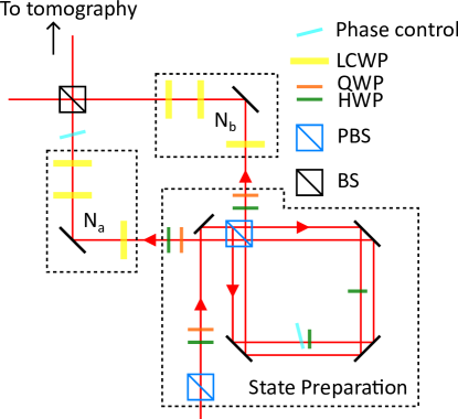
2 Experimental setup
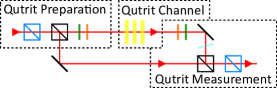
The construction of our superposition of channels is based on heralded single photons, with the polarization degree of freedom playing the role of the system qubit and the path degree of freedom playing the role of the control qubit. In our setup, illustrated in figure 1, we prepare the photon polarization and path by using a set of waveplates and a Sagnac interferometer respectively. After the preparation, the photon goes into either path a or path b of a Mach-Zehnder interferometer, with the paths corresponding to random unitary channels and respectively. These random unitary channels each consist of three liquid crystal waveplates (LCWP), where the random unitary is implemented by changing the LCWP voltage. Path a also passes through a glass plate that controls the phase between the two paths, after which the two paths interfere at a beam splitter (BS).
The unitary performed by the Mach-Zehnder is given by
| (1) |
where and are the unitary operators corresponding to the polarization rotation given by LCWPs in and , and corresponds to the projectors on the path qubit, and the indices denote elements in the set of all possible unitary operators. To simulate the effects of a random unitary channel, we perform our experiment using all possible combinations of unitaries and and taking a weighted average of the results with weightings and that correspond to the probabilities of those unitaries in the respective random unitary channel. This effectively emulates random unitary channels for and , with Kraus operators given by and . The overall channel given by our Mach-Zehnder interferometer acting on some input path and polarization state is then also a random unitary channel, given by
| (2) |
with the summation operation summing over the entire set of possible unitary operators and weighted over the probability of those unitaries .
To understand the nature of the implementation-dependence of superposing qubit channels, we will compare the superposed channels created by superposing two different implementations of the depolarizing channel. First, we remind readers of some mathematical properties of the depolarizing channels. We note that a set of Kraus operators in the qubit Hilbert space can be expressed in terms of the qubit operator basis formed by the identity and the three Pauli operators, such that
| (3) |
| (4) |
where , , and are Pauli matrices (and will be used interchangeably with , , and ), and is the identity. The channel formed by the set of Kraus operators describes a depolarizing channel if it can be described by a random unitary channel, where , , and are performed with probability and the identity operator with probability . Mathematically, the decomposition of a depolarizing channel from equation 4 gives
| (5) |
where is the degree of depolarization, with corresponding to a completely depolarizing channel.
We will denote the two implementations of the depolarizing channel as the phase-coherent and phase-incoherent implementations, with all implementation-specific symbols being denoted with the unbracketed superscript and respectively. More precisely, in the phase-coherent implementation, four different operators are randomly implemented for each channel. These operators are, for and respectively,
| (6) |
where and , and and are the phase factors associated with each Pauli operators in the phase-coherent implementation. The probabilities and phase factors and are given by
| (7) |
| (8) |
The and phase factors correspond to the configuration of the LCWPs in and in our physical setup, where a aligned LCWP comes before the aligned LCWP in and the reverse is true for .
In the phase-incoherent implementation, we completely randomize the path phase by add four additional operators to the two operator sets in the phase-coherent implementation. These four additional operators correspond to the operators in the phase-coherent implementation with an additional phase. The phase-incoherent implementation, therefore, has operators
| (9) |
Note in the phase-incoherent implementation, the random unitary operators implemented in and are not necessarily equal, but rather are drawn independently from the same set of unitaries. Experimentally, this phase is implemented by the third LCWP with an optical axis aligned perpendicularly to the second LCWP. By tuning the voltages of both LCWP simultaneously, a polarization-independent phase shift can be applied to the photons. This phase acts as a global phase when channels and are not in superposition.
3 Implementation Dependence
A distinct feature of superposing channels is the dependence of the superposed channel map on the operators used to implement the non-superposed channels used in the superposition. As a consequence, the choice of using implementations 6 or 9 for the simple qubit channels and will result in two different versions of the two-qubit channel .
When the path qubit is prepared and post-selected on , the resulting post-selected qubit channel
| (10) |
will have Kraus operators given by
| (11) |
The implementation-dependence of the post-selected qubit channel can be seen as a consequence of being sensitive to the global phases, which are reflected in and , of the two channels and . These global phases of the two channels become phases between states and in the control qubit when the channels are put in a superposition. The Pauli decomposition of the post-selected channel helps us illuminate the nature of the post-selected channel’s dependence on channel implementation. For the phase-coherent implementation, the Pauli decomposition of the set of Kraus operators given by results in
| (12) |
The phase-dependence of the post-selected channel can thus be seen by noting equation 12’s dependence on the terms.
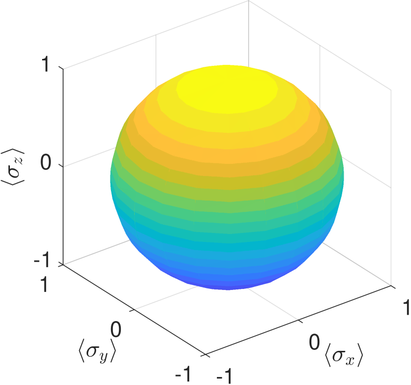
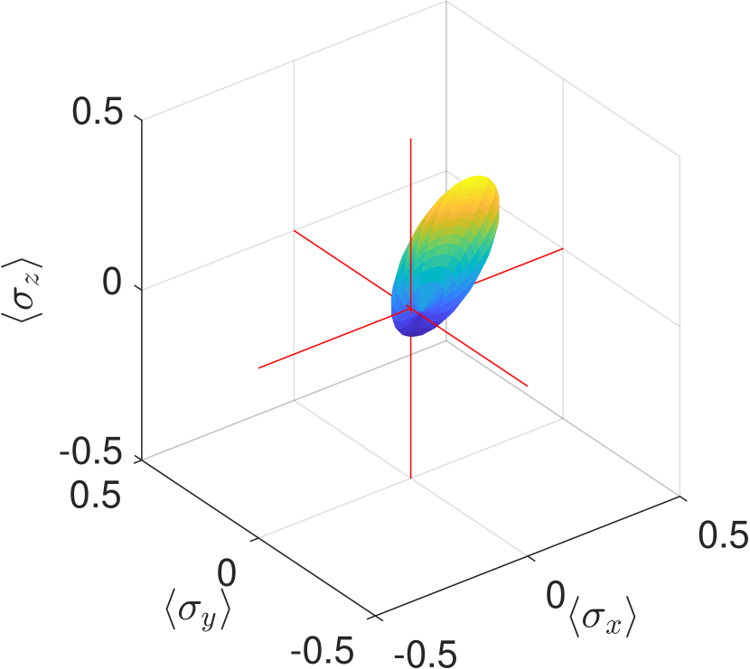
Examining figure 2, which shows the Bloch sphere representation of the post-selected channel, we can see that the eigenstate with the positive eigenvalue for the Hadamard unitary experiences the least amount of depolarization from the post-selected channel in the phase-coherent implementation. An explanation for this is given in appendix D.
In contrast, the phase-incoherent implementation has a Pauli decomposition that yields
| (13) |
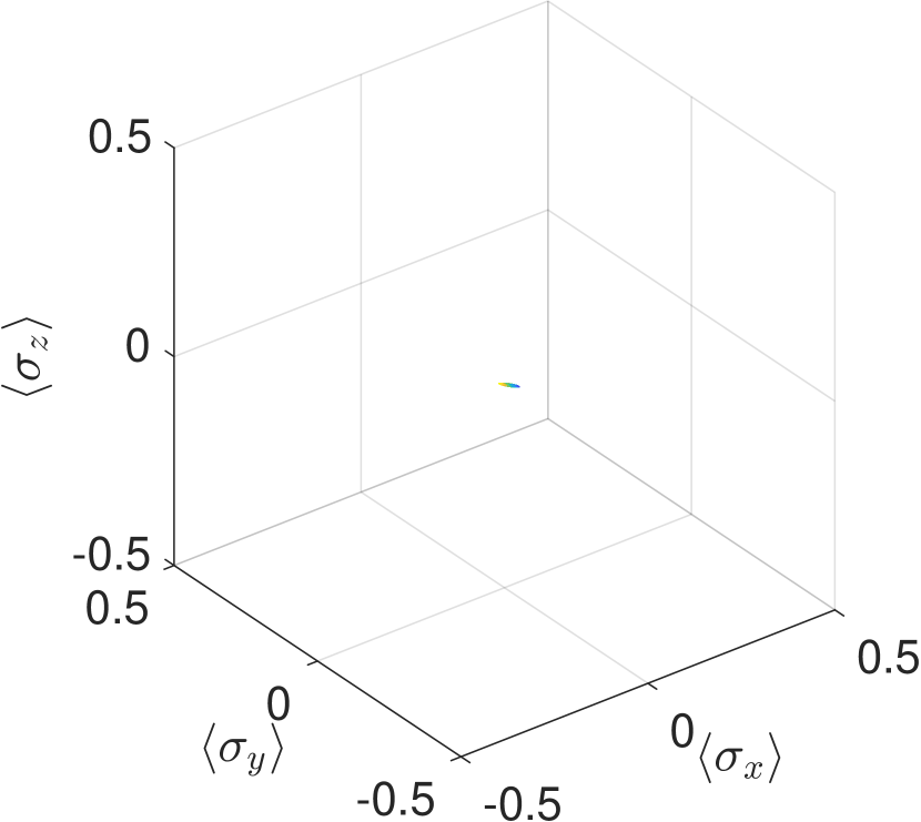
The inclusion of a duplicate set of operators with a phase shift causes the contribution of the operator phase components and to cancel out in the Pauli decomposition. Substituting the probabilities of equation 7 into 13, we have . This indicates that the post-selected channel given by the phase-incoherent implementation results in a depolarizing channel with a post-selection probability of , exactly the same as the channels and .
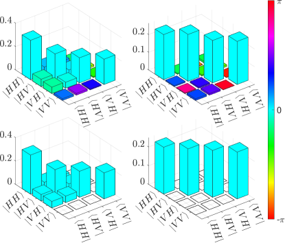
Figures 2 and 3 highlight this implementation-dependence quantitatively through the tomographic reconstruction of the phase-coherent and phase-incoherent channels, and qualitatively in the channels’ shape on the Bloch sphere. As seen from the figures, for the phase-coherent implementation with Kraus operators and with , the post-selection results in a channel that is not completely depolarizing, even though the individual channels themselves are. This is in contrast to the phase-incoherent implementation with Kraus operators and , where due to the randomization of channel phases, the effect of post-selection reduces to a classical mixture of depolarizing channels, resulting in a completely depolarizing channel. The result of superposing two phase-incoherent implementations also extends to the superposition of one phase-coherent and one phase-incoherent implementation.
4 Qutrit Model
The inability of the simple qubit channel map to translate directly to a unique description of the superposed channel demonstrates that it is insufficient for describing the physical operations of the channel under superposition. This is because of the introduction of the control qubit, which requires that we can effectively ‘turn off’ a quantum channel by sending in zero photons. Thus, apart from the description of the channel’s action on the polarization qubit, an additional description of the channel action on the vacuum state needs to be included, as noted by [8, 17, 18], which in turn results in the simple qubit channels becoming qutrit channels: two states from the original polarization qubit channel, and one new state corresponding to the vacuum (‘off’) state. Here, we perform qutrit channel tomography for the aforementioned qutrit channels explicitly through the procedures described in appendix E. Our qutrit Hilbert space consists of the vacuum (zero photon) state , the polarization state H , and the polarization state V . When performing tomography for channel (), the preparation for the state is equivalent to not sending the photon into the channel (). Conceptually, the qutrit tomography procedures described in appendix E are equivalent as follows. The preparation of the qutrit state is done by first preparing the photon in the H polarization and path state in either or . Then, for the channel tomography for (), we vary the photon polarization only if the photon is in the () path state. This has the effect of preparing a state in the Hilbert space spanned by , , and . For the tomography of channel (), channel () is always set to the identity channel. Similar to the input qutrit preparation, the qutrit is measured by performing polarization measurement only on the () path and a measurement of the path qubit. A setup equivalent to the qutrit tomographic procedure is outlined in figure 6.
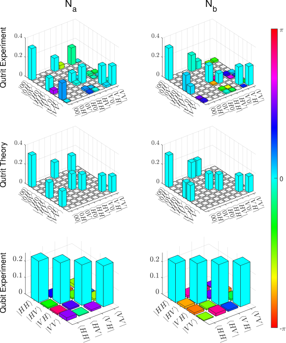
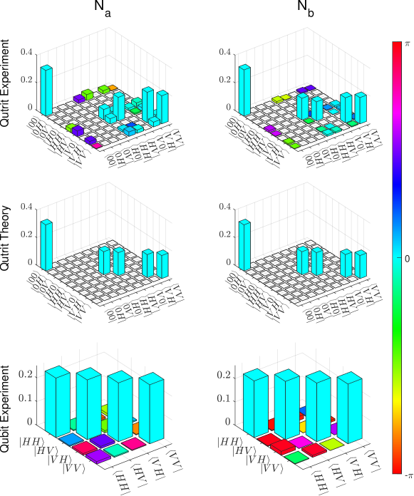
Figures 4 and 5 show the tomographic results for qutrit channels of and for both implementations with . In these figures, the effects of the operator phase of the two implementations can be observed in the coherences between the polarizations and the vacuum state. Both channels in the phase-coherent implementation partially preserve coherence between and but differ by the coherence between and (which is partially preserved for and not for ), and the coherence between and (which is partially preserved for and not for ). On the other hand, neither channel preserves any coherences in the phase-incoherent implementation, resulting in a purely diagonal channel dual state.
5 Channel Hierarchy
Fundamentally, the simple qubit ( and ), post-selected (), Mach-Zehnder (), and qutrit ( and ) channel model(s) are descriptions of the same setup with differing levels of detail. It is therefore helpful to order those different descriptions based on these levels. The simple qubit and post-selected channels can be derived from the Mach-Zehnder channel by preparing and measuring the control in the appropriate state, and the Mach-Zehnder channel can in turn be derived by preparing and measuring the input and output in the one-photon subspace of the two-qutrit channel given by
| (14) |
We do not have direct experimental access to the two-qutrit channel as the design of our setup does not allow us to access and simultaneously. Nonetheless, it is important to discuss it conceptually in this section. Based on the channel description’s level of detail, the channel models can be partially ordered in the following way
| (15a) | |||
| (15b) | |||
| (15c) | |||
where any channel description ordered lower on the partial ordering can be extracted from a channel description ordered higher on the partial ordering, either by taking a subspace or post-selecting on the channel higher on the ordering. More broadly speaking, our partial ordering here is a specific kind of channel divisibility [22, 23] that involves dimensional reduction.
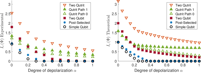
With this partial ordering in mind, we compare the maximum coherent information of our depolarizing channels under different channel models and implementations. The maximum coherent information is related to the ability of a quantum channel to generate entanglement across two parties and can be understood as the amount of quantum information that can be transmitted through a single use of the channel [24]. We have chosen to use this quantity over classical channel capacity and quantum channel capacity due to the former not capturing the quantum characteristics of channels and the latter being hard to compute. The maximum coherent information is given by
| (16) |
where is the purification of the state and is the von Neumann entropy, given by
| (17) |
Figure 7 shows the maximum coherent information at various levels of depolarization. The capacity enhancement when simple qubit channels are post-selected in a superposition can be seen at going from 0 to approximately 0.4, where the maximum coherent information from the post-selected channel is strictly greater than that of the qubit channel.
It is important to stress that the maximum coherent information for the two-qutrit channel, unsurprisingly, is strictly greater than all other channel models under investigation. Therefore, no capacity enhancement would be found if one used the appropriate two-qutrit channel model or superposition channel model to describe the post-selected channel.
6 Discussion
The capacity enhancement in coherently controlled channels may seem surprising at first, yet this surprise is perhaps due to the implicit assumption that a coherently controllable channel can be trivially implemented using its non-controlled counterpart. This is not true, as the inclusion of the control qubit necessitates an expanded description of the channels to accommodate the transmission of the extra control qubit. For the case of superposing qubit channels, the channel action on vacuum needs to be accounted for. To illustrate this, we have experimentally reconstructed relevant qutrit channels for three different implementations of the depolarizing channel. Indeed, for depolarizing channels, the quantum information that one can send through the superposition is strictly less than that of the relevant qutrit channels. It is therefore more appropriate to attribute the increase in channel capacity of superposing channels to the required expansion of the channel’s input and output Hilbert space, rather than the act of superposition itself.
While the implementation-dependence of coherently controlled channels on its non-coherently controlled counterpart is a feature of the superposed channel that is not shared for all coherently controlled channels, all coherent control schemes require the transmission of an extra control qubit. Our work provides insight into how channel expansion contributes to the capacity enhancement in coherently controlled channels.
Appendix A LCWP Characterization
We used a total of six LCWPs in our experiment, two from Thorlabs and four from Meadowlark Optics. They are distributed in Mach-Zehnder interferometer such that there are two Meadowlark LCWPs and one Thorlabs LCWP in each arm, and ordered such that incoming light always goes through the two Meadowlark LCWPs first. The voltage to phase retardance for each LCWPs is calibrated by sending horizontally polarized light through the LCWP with its optical axis at 45 degrees, with measurement of the subsequent light in the horizontal/vertical basis. Input voltage-dependent absorption was also characterized, and was determined to be at most a change.
Appendix B Photon Souce
We generated SPDC photons using PPKTP type-II co-linear down-conversion, where one of the photons is used as a herald, resulting in heralded single photons per second. After the single-mode fibre-coupling into a detector, we detect heralded single photons per second, with losses due to unwanted absorption, reflection, and single-mode coupling inefficiencies.
Appendix C Systematic errors
Deviations between the theoretical and experimental results in figures 2, 4 and 5 are dominated by three sources of systematic error. The first is due to phase fluctuation in our Mach-Zehnder interferometer of about (comparable to, in figure 4 the phase error between and of for the phase-coherent implementation). The second is the calibration error in the polarization rotation axis of the LCWPs of about . Finally, there is a polarization dependence absorbance of at most present in our setup.
Appendix D Post-selected channel map of phase-coherent implementation
| 0 | |||||
There are three main reasons for the post-selected channel to take its form given in figure 2(b). Firstly, due to phases and , the post-selection filters out the cases where both and implement , which takes one eigenstates of the Hadamard to the other, as the random unitary. Secondly, when one of the channels implements and the other implements , the resulting operator that an input state experiences is the Hadamard, which leaves the unitary’s eigenstate unchanged. Thirdly, when one of the channels implements identity and the other implements either or , the resulting operator is a projector onto the eigenstate with the positive eigenvalue for and respectively. These two states have a higher overlap to the eigenstate with the positive eigenvalue (than the negative eigenvalue) for the Hadamard unitary. A summary of these superpositions and the resulting operators can be found in table 1. Overall, this results in the post-selected channel leaving the positive-eigenvalued eigenstate for the Hadamard to be the least disturbed, resulting in a channel that has a Bloch sphere representation of an elliptical disc with its longest semi-axis in the direction of the Hadamard eigenstates and its center displaced towards the positive-eigenvalued Hadamard eigenstate, as illustrated in figure 2.
Appendix E Qutrit Tomography
Here, we perform qutrit channel tomography for the aforementioned qutrit channels explicitly. To perform tomography on the vacuum state, we note that the unitary operators for the qutrit channels and can be described by
| (18) |
with and being projectors onto the zero photon states for channels and respectively, and and being the unitary operators for channels and described under the qutrit channel model. These sets of qutrit unitaries form the random unitary qutrit channels and (and that ), which have the feature that they preserve photon number.
For any accurate tomographic reconstruction of the channel , we require a way to extract where
| (19) |
for a completely spanning set of states . In our experiment, we have direct access to the one photon subspace of the two-qutrit channel in the form of our Mach-Zehnder channel . In the Mach-Zehnder channel, the vacuum state for channel () can be accessed by preparing the path state to be in ().
The probability of measuring a certain output state given an input state is given by , where
| (20) |
To perform qutrit channel tomography on channel , we need to set , where takes the input polarization state to the output polarization state. Thus, the probability amplitude for the qutrit channel can be found by substituting this condition into equation 20. Performing the substitution, we have
| (21) |
where
| (22) | ||||
and
| (23) | ||||
where (), (), and () is the probability amplitude of zero photons, one photon, and one photon being sent to (measured from) channel . We also note that acts on the qutrit Hilbert space with basis vectors , , and . and can take on the values of and when one of the paths of the interferometer is physically blocked, or the value of when both paths are unblocked. The probability of measuring some output state given any input state will, as a result, be independent of polarization when the path qubit is in the state, effectively reducing the dimensions of the channel from a two-qubit channel to a qutrit channel where three orthogonal states exist for the entire apparatus – one for the photon in path 1, one for the photon in path 0 and horizontally polarized, and one for the photon to be in path 0 and vertically polarized. This path state can thus be re-labelled as the vacuum state, as a reference to the fact that the photon is not in path 0. A similar procedure is repeated for channel .
References
- [1] Daniel Ebler, Sina Salek, and Giulio Chiribella. “Enhanced communication with the assistance of indefinite causal order”. Physical Review Letters120 (2018).
- [2] Giulio Chiribella, Giacomo Mauro D’Ariano, Paolo Perinotti, and Benoit Valiron. “Quantum computations without definite causal structure”. Physical Review A - Atomic, Molecular, and Optical Physics88 (2013).
- [3] Márcio M. Taddei, Jaime Cariñe, Daniel Martínez, Tania García, Nayda Guerrero, Alastair A. Abbott, Mateus Araújo, Cyril Branciard, Esteban S. Gómez, Stephen P. Walborn, Leandro Aolita, and Gustavo Lima. “Computational advantage from the quantum superposition of multiple temporal orders of photonic gates”. PRX Quantum2 (2021).
- [4] K. Goswami, Y. Cao, G. A. Paz-Silva, J. Romero, and A. G. White. “Increasing communication capacity via superposition of order”. Physical Review Research2 (2020).
- [5] Giulia Rubino, Lee A. Rozema, Adrien Feix, Mateus Araújo, Jonas M. Zeuner, Lorenzo M. Procopio, Časlav Brukner, and Philip Walther. “Experimental verification of an indefinite causal order”. Science Advances3 (2017).
- [6] Yu Guo, Xiao Min Hu, Zhi Bo Hou, Huan Cao, Jin Ming Cui, Bi Heng Liu, Yun Feng Huang, Chuan Feng Li, Guang Can Guo, and Giulio Chiribella. “Experimental transmission of quantum information using a superposition of causal orders”. Physical Review Letters124 (2020).
- [7] Lorenzo M. Procopio, Amir Moqanaki, Mateus Araújo, Fabio Costa, Irati Alonso Calafell, Emma G. Dowd, Deny R. Hamel, Lee A. Rozema, Časlav Brukner, and Philip Walther. “Experimental superposition of orders of quantum gates”. Nature Communications6 (2015).
- [8] Giulia Rubino, Lee A. Rozema, Daniel Ebler, Hlér Kristjánsson, Sina Salek, Philippe Allard Guérin, Alastair A. Abbott, Cyril Branciard, Časlav Brukner, Giulio Chiribella, and Philip Walther. “Experimental quantum communication enhancement by superposing trajectories”. Physical Review Research3 (2021).
- [9] Lorenzo M. Procopio, Francisco Delgado, Marco Enríquez, Nadia Belabas, and Juan Ariel Levenson. “Communication enhancement through quantum coherent control of n channels in an indefinite causal-order scenario”. Entropy21 (2019).
- [10] Lorenzo M. Procopio, Francisco Delgado, Marco Enríquez, Nadia Belabas, and Juan Ariel Levenson. “Sending classical information via three noisy channels in superposition of causal orders”. Physical Review A101 (2020).
- [11] Giulio Chiribella and Hlér Kristjánsson. “Quantum shannon theory with superpositions of trajectories”. Proceedings of the Royal Society A: Mathematical, Physical and Engineering Sciences475 (2019).
- [12] Giulio Chiribella, Manik Banik, Some Sankar Bhattacharya, Tamal Guha, Mir Alimuddin, Arup Roy, Sutapa Saha, Sristy Agrawal, and Guruprasad Kar. “Indefinite causal order enables perfect quantum communication with zero capacity channels”. New Journal of Physics23 (2021).
- [13] Giulio Chiribella, Matt Wilson, and H. F. Chau. “Quantum and classical data transmission through completely depolarizing channels in a superposition of cyclic orders”. Physical Review Letters127 (2021).
- [14] Sk Sazim, Michal Sedlak, Kratveer Singh, and Arun Kumar Pati. “Classical communication with indefinite causal order for n completely depolarizing channels”. Physical Review A103 (2021).
- [15] N. Gisin, N. Linden, S. Massar, and S. Popescu. “Error filtration and entanglement purification for quantum communication”. Physical Review A - Atomic, Molecular, and Optical Physics72 (2005).
- [16] Daniel K.L. Oi. “Interference of quantum channels”. Physical Review Letters91 (2003).
- [17] Alastair A. Abbott, Julian Wechs, Dominic Horsman, Mehdi Mhalla, and Cyril Branciard. “Communication through coherent control of quantum channels”. Quantum4 (2020).
- [18] Philippe Allard Guérin, Giulia Rubino, and Časlav Brukner. “Communication through quantum-controlled noise”. Physical Review A99 (2019).
- [19] Francesco Massa, Amir Moqanaki, Ämin Baumeler, Flavio Del Santo, Joshua A. Kettlewell, Borivoje Dakić, and Philip Walther. “Experimental two-way communication with one photon”. Advanced Quantum Technologies2 (2019).
- [20] Flavio Del Santo and Borivoje Dakić. “Two-way communication with a single quantum particle”. Physical Review Letters 120, 1–5 (2018).
- [21] Mateus Araújo, Adrien Feix, Fabio Costa, and Časlav Brukner. “Quantum circuits cannot control unknown operations”. New Journal of Physics16 (2014).
- [22] Teiko Heinosaari and Takayuki Miyadera. “Incompatibility of quantum channels”. Journal of Physics A: Mathematical and Theoretical50 (2017).
- [23] Cristhiano Duarte, Lorenzo Catani, and Raphael C. Drumond. “Relating compatibility and divisibility of quantum channels”. International Journal of Theoretical Physics61 (2022).
- [24] John Watrous. “The theory of quantum information”. Chapter 8. Cambridge University Press. (2018).