Analysis of Cooperative and Non-Cooperative Architectures for Multi-Plane On-Orbit Refueling
Abstract
As many satellite constellations are proposed, deployed, and operated, their maintenance becomes increasingly important to provide satisfactory services; therefore, on-orbit refueling to spacecraft has become one of the most promising technologies for realizing more sustainable space development. This paper develops an analytical model to examine two types of mission architectures for multi-target on-orbit refueling missions: a non-cooperative architecture and a cooperative architecture. In the (rather conventional) non-cooperative refueling architecture, a servicer spacecraft visits passive targets one by one, whereas, in the cooperative refueling architecture, both the servicer and the targets can actively maneuver to complete refueling cooperatively. This paper analytically compares the fuel mass required in each architecture to support the decision-making process of mission architects. Furthermore, the condition under which the cooperative architecture becomes more efficient than the non-cooperative architecture is analytically derived. The sensitivities of this condition against key mission parameters, such as the number of targets and their inclination, are also analyzed through a case study of multi-plane multi-target on-orbit refueling in low Earth orbits.
Nomenclature
| = | standard acceleration due to gravity |
| = | specific impulse |
| = | inclination |
| = | general mass |
| = | total refuel mass |
| = | required refuel mass |
| = | number of targets |
| = | relative argument of latitude |
| = | critical mass ratio between a servicer and targets where the suggested mission architecture changes |
| = | change in velocity |
| Subscripts | |
| c = | cooperative case |
| F = | mass after a whole campaign |
| f = | mass after an orbital transfer |
| I = | mass before a whole campaign |
| in = | mass at inbound transfer |
| n = | non-cooperative case |
| out = | mass at outbound transfer |
| s = | servicer |
| t = | target |
| 0 = | mass before an orbital transfer |
1 Introduction
Satellite constellations have been proposed, researched, and operated for various objectives such as Earth observation, navigation, and communication [1, 2, 3, 4, 5]. For instance, Planet operates a constellation, PlanetScope, to obtain images of Earth’s land frequently. These images acquired from satellite constellations are, for example, used for remote sensing [6]. The Global Positioning System (GPS), which is now broadly used to navigate many devices such as cars and smartphones, also utilizes a satellite constellation of about 30 satellites in six different orbital planes in medium Earth orbit. Among communication constellations, constellations for internet access, such as Starlink operated by SpaceX, are becoming popular. SpaceX plans to deploy about 12,000 satellites in total in Low Earth Orbit (LEO) to provide low-latency internet access in many countries. These services from constellations have become essential to our daily lives and emergencies, such as disaster operations management and Internet access during a war.
To keep providing satisfactory performances to users, maintaining these constellations is crucial. Replacing malfunctioning satellites has been proposed and researched as one maintenance approach [7, 8]. Cornara et al. [7] analyzed three different replacement strategies: launching new satellites on-demand, placing spare satellites in close orbits, and placing these spare satellites in parking orbits. Jakob et al. [8] proposed an analytical model of the parking orbits strategy by leveraging a multi-Echelon inventory policy.
Another potential maintenance approach is to service these satellites on orbit (On-Orbit Servicing, OOS)[9, 10]. The validity of the general OOS concept has been shown in Refs. [11, 12, 9]. For instance, Hatty [12] analyzed the economical viability of extending the operational period of Landsat 7 by a robotic spacecraft, OSAM-1, and compared it to the cost of replacing the satellite. Luu and Hastings [9] focused on LEO constellations and explored a tradespace where OOS could be beneficial. Some flight demonstrations for essential technologies for OOS were also performed [13, 14]. ETS-VII developed and operated by NASDA (now merged into JAXA) demonstrated a berthing operation to capture a passive free-flying target [15, 13]. The Orbital Express Demonstration System mission managed by DARPA also demonstrated capturing and berthing of a free-flying target followed by transferring of Orbital Replacement Units [14]. Furthermore, successful dockings of Mission Extension Vehicles to actual commercial satellites, Intelsats, demonstrates the feasibility of prolonging the operational period of satellites[16, 17], As these examples show, OOS is becoming even more promising.
An OOS mission to a satellite constellation can be considered a multi-target OOS mission. Analyses and optimizations of various kinds of multi-target OOS missions have been extensively researched [18, 19, 20, 21, 22, 23, 24]. Bourjolly et al. [18] minimized the total energy or time required for an OOS mission by solving a time-dependent, moving-target traveling salesman problem. Meng et al. [19] proposed a new system architecture for on-orbit refueling, “1+N”, consisting of one fuel storage station and refueling vehicles, and a multi-objective optimization was conducted to find an optimal deployment strategy. Shen et al. [20] also conducted a multi-objective optimization, but for a multiple debris removal mission. Sarton du Jonchay and Ho [21] quantitatively compared the responsiveness of two OOS infrastructures, the one "With Depot" and the one "Without Depot." Ho et al. [24] further developed a semi-analytical OOS model with a depot considering the queue of services and the capacity of the depot. In Ref. [22], Sarton du Jonchay et al. developed an optimization framework to help decision-makers to make operational and strategic plans under uncertainties in service demand. Sarton du Jonchay et al. [23] further extended this framework to handle OOS with low-thrust orbital transfers.
These studies reviewed above have employed mission architectures with one active servicer or multiple active servicers and passive targets (i.e., non-cooperative OOS architectures). Another approach, peer-to-peer (P2P) OOS (especially on-orbit refueling) strategies have also been researched [25, 26, 27, 28, 29]. In the later egalitarian P2P refueling studies [28, 29], all spacecraft in a constellation are assumed to be capable of conducting orbital transfers and refueling another spacecraft. Dutta and Tsiotras [28] minimized the fuel consumption during the orbital transfers proposing a network flow formulation of this problem. Dutta et al. [29] further extended this strategy to low-thrust maneuvers, developed a solver to solve the optimization problem, and demonstrated it through two mission scenarios.
In addition to these two architectures in on-orbit constellation servicing, non-cooperative OOS and P2P OOS, a new architecture, cooperative OOS, has been recently proposed [30, 31, 32]. This architecture is a mixture of non-cooperative and P2P OOS allowing maneuvering by any spacecraft in the architecture while targets (spacecraft to be serviced) cannot service any other spacecraft. Zhao et al. [31] analytically derived an expression of the total propellant mass for cooperative architectures and compared it to the cost with a traditional non-cooperative architecture considering the perturbation. They showed the benefit of employing this architecture through a case study of a coplanar on-orbit refueling mission. Cox et al. [32] employed the consensus-based bundle algorithm (CBBA) for the initial planning and scheduling of the cooperative OOS. Refs. [30, 31] compared the cooperative and the conventional non-cooperative architectures and showed the potential less fuel required in the cooperative architectures. However, the effect of the target constellation parameters such as orbital elements and the number of targets on the required fuel mass in both architectures is yet to be discovered. To provide a more general and comprehensive comparison between cooperative and non-cooperative architectures to help mission architects, this paper analyses non-coplanar multi-target OOS missions with multiple mission architectures, and addresses the conditions that make one architecture better than the other.
The rest of the paper is organized as follows: mathematical derivation of the initial mass of a servicer in a cooperative architecture is introduced in Sec. 2. Based on the derived initial mass, Sec. 2.4 compares cooperative and non-cooperative architecture analytically. Sec. 3 discusses the value of cooperative architectures through case studies. The cases employed here are inspired by the Starlink constellation. Finally, Sec. 4 concludes this paper with some remarks.
2 Modeling Multi-Target On-Orbit Refueling Architectures
This section first introduces the considered on-orbit refuel mission architecture (Sec. 2.1), followed by the derivation of the initial mass of a servicer (Sec. 2.2) and total refuel mass (Sec. 2.3) in this architecture. Then, Sec. 2.4 analytically compares the derived mass between both cooperative and non-cooperative architectures.
2.1 Overview of On-Orbit Refueling Architecture
A general multi-target on-orbit refueling architecture considered in this paper follows the sequence below:
-
1)
a single servicer is launched and transferred to the orbital plane of the 1st target;
-
2)
the servicer rendezvous with the target, refuel it, and move to the next target;
-
3)
repeat Phase 2) until all targets are refueled;
-
4)
the servicer goes back to its original position with the original inclination and the relative argument of latitude.
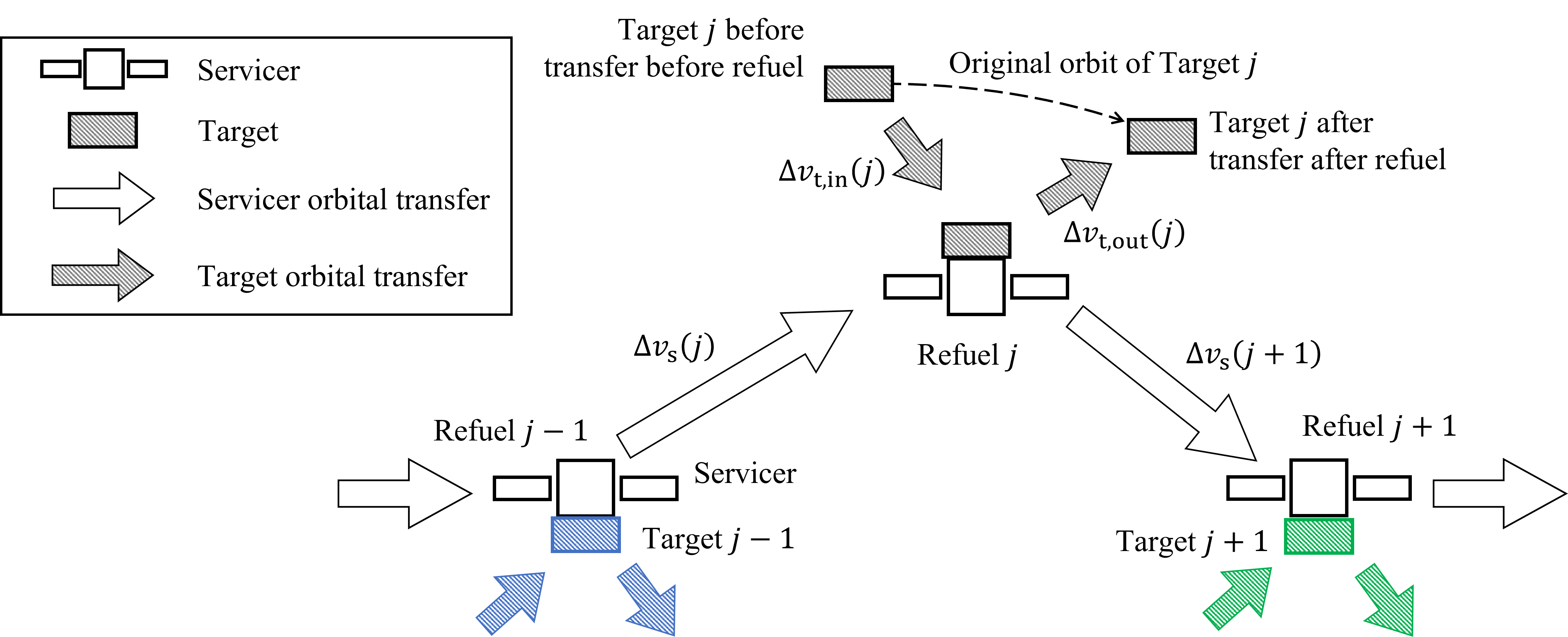
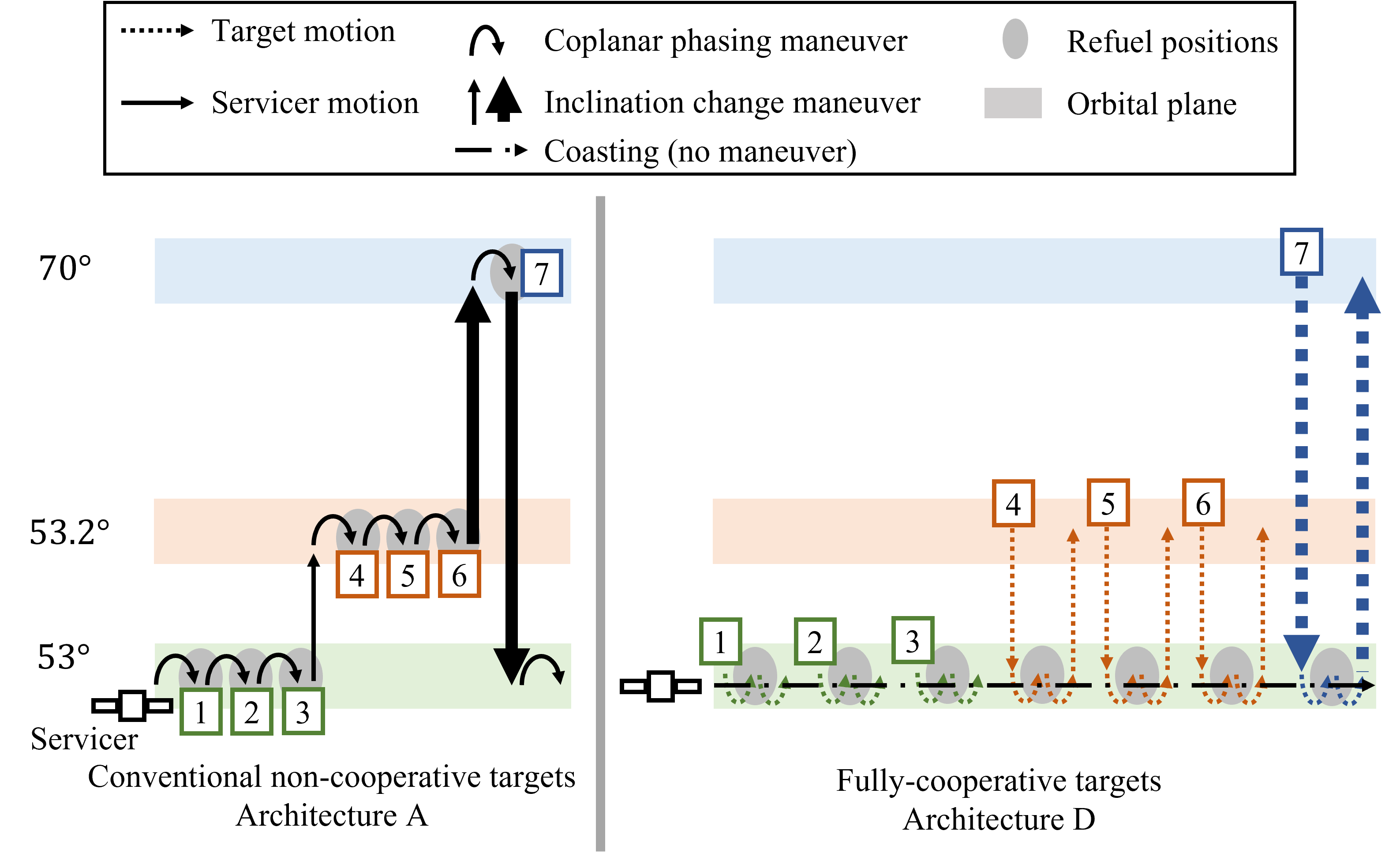
In the case of a cooperative refueling architecture, both the servicer and a target are capable of orbital transfers to rendezvous in Phase 2 (Fig. 1), whereas in the conventional non-cooperative architecture, only the servicer can conduct orbital transfers to the rendezvous point. Note that cooperative target spacecraft consume some fuel to fly to a rendezvous point and come back to their original position after refueling (See Fig. 1), and therefore, they need to receive more fuel from the servicer than those in the non-cooperative architecture to compensate this extra fuel consumption.
2.2 Initial Mass of Servicer
To compare the cooperative and non-cooperative architectures introduced above, the mathematical expressions of the initial mass of the servicer in both architectures are derived in this subsection. For the th rendezvous (See Fig. 1), the Tsiolkovsky rocket equation can be written as
| (1) |
where and denote the mass of the servicer before and after the th orbital transfer, respectively. Since the initial servicer mass before the th orbital transfer is the same as the servicer mass after the th refuel,
| (2) |
where represents the total refuel mass that the servicer gave to the th target. Modifying Eq. (1) to the th orbital transfer and combining it with Eq. (2) leads to
| (3) |
From this equation, assuming the number of targets is , the initial mass of the servicer at the beginning of the whole sequence, , is derived as follows:
| (4) |
We further assume the final mass of the servicer is given (e.g., the dry mass) and treat Phase 4) as the th orbital transfer. Thus, the given final mass is . From Eqs. (1) and (4), the relationship between the initial mass, , and the final mass, of the servicer of the whole scenario , is derived as follows:
| (5) |
2.3 Total Refuel Mass
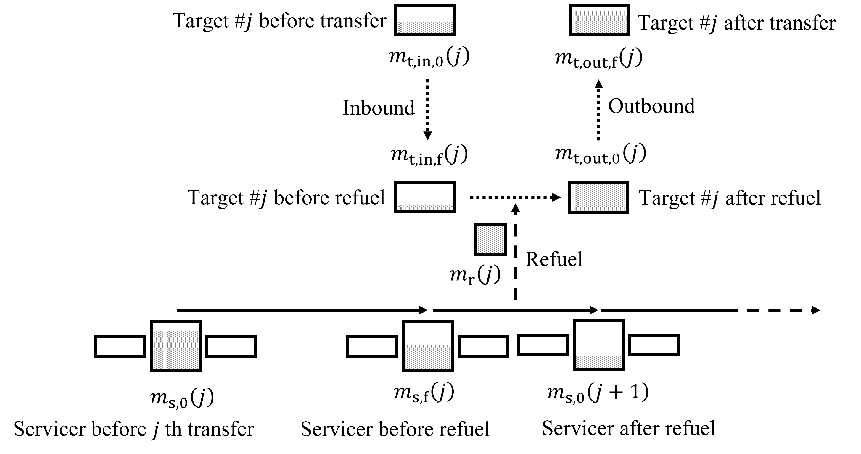
For the cooperative architecture, a target comes from its original position to a rendezvous spot, and then the target goes back to the position where it would be if there was no active orbital transfer (see Fig. 1). The rocket equations of both transfers by Target can be written as
| (6) | ||||
| (7) |
where and are the initial and the final mass of the first (inbound) transfer, and are those of the second (outbound) transfer (Fig. 2), and and are the required for each transfer. To fairly compare the cooperative and the non-cooperative architectures, the final mass of Target (after the second transfer), , is assumed to be the same as the post-refuel mass of that Target in the non-cooperative architecture, i.e., a target in either architecture have the same amount of “usable” fuel supplied after every orbital transfer is completed. Therefore, the relationship between the initial mass of the Target , , and the final mass of the Target , , becomes
| (8) |
where is the required “usable” refuel amount by Target (i.e., the total refuel amount for the non-cooperative architecture). Furthermore, the relationship between the final mass after the inbound transfer and the initial mass before the outbound transfer is expressed as
| (9) |
where is for the cooperative architecture. From Eqs. (6) - (9), the total refuel mass for Target is derived as follows:
| (10) |
Substituting Eq. (10) into Eq. (5), the initial mass of the servicer in the cooperative architecture, , can be analytically derived:
| (11) |
2.4 Comparison of Initial Mass of Servicer
For designing a refueling architecture, a key cost metric would be the initial mass (wet mass) of the servicer. To obtain conditions that the cooperative case is favored, the following inequality is considered:
| (14) |
From Eqs. (11) and (13), assuming all targets have the same initial mass (i.e., ), and they require the same amount of refuel (i.e., ), the modified version of this inequality is expressed as follows:
| (15) | ||||
If Inequality (LABEL:eq:mass_ineq2) is satisfied, the initial mass of the servicer can be smaller for the cooperative case than that of the conventional non-cooperative mission architecture. Note that this inequality depends on the required of both the servicer, and the targets, as well as the final mass of the servicer, the initial mass of the targets, the required refuel mass, and the specific impulse of both the servicer and the targets.
Inequality (LABEL:eq:mass_ineq2) also indicates that one critical parameter to evaluate the architectures is the ratio between the final servicer mass and the initial target mass, . The numerator of this ratio, the final servicer mass, is the dry mass of the servicer, whereas the denominator of this ratio, the initial target mass, is the target mass before the entire fuel campaign starts. Note that, despite the name “initial,” the initial target mass is not a fully-fueled target; rather it is the mass of the target when refueling is requested, at which point its fuel tank can be near empty although not necessarily completely empty, especially for the cooperative architecture.
From Inequality (LABEL:eq:mass_ineq2), we can find a crossover point of this mass ratio, beyond which the cooperative architecture leads to a smaller initial servicer mass than the non-cooperative architecture. In this paper, we call this value the “critical mass ratio,” denoted by . Refer to Appendix.1 for the analytical expression of the critical mass ratio. In general, the required for the servicer is lower in the cooperative architectures. Therefore, from Inequality (LABEL:eq:mass_ineq2), if is smaller than the critical mass ratio (i.e., a light-weight servicer and heavy-weight targets), the initial servicer mass in the non-cooperative architecture can be smaller than the cooperative architecture, i.e., the non-cooperative architecture is favored. Instead, if the value is bigger than the critical mass ratio (i.e., a heavy-weight servicer and light-weight targets), the cooperative architecture can be beneficial. Therefore, calculating the ratio and comparing it with the critical mass ratio at the phase of conceptual study or preliminary analysis of designing an on-orbit refueling mission gives mission architects a recommended architecture between these two mission architectures. This ratio, , can be estimated from the mass of targets requested from customers and the required payloads of the servicer such as a robot arm for capturing the targets.
3 Case Study
In this section, case studies of on-orbit refueling missions in multiple architectures are investigated. First, Sec. 3.1 introduces the overview of a target LEO satellite constellation and mission architectures considered in this paper. The initial mass of the servicer in each architecture is summarized in Sec. 3.2. Finally, the sensitivity of each parameter to the the critical mass ratio is discussed in Sec. 3.3.
3.1 Case Study Overview
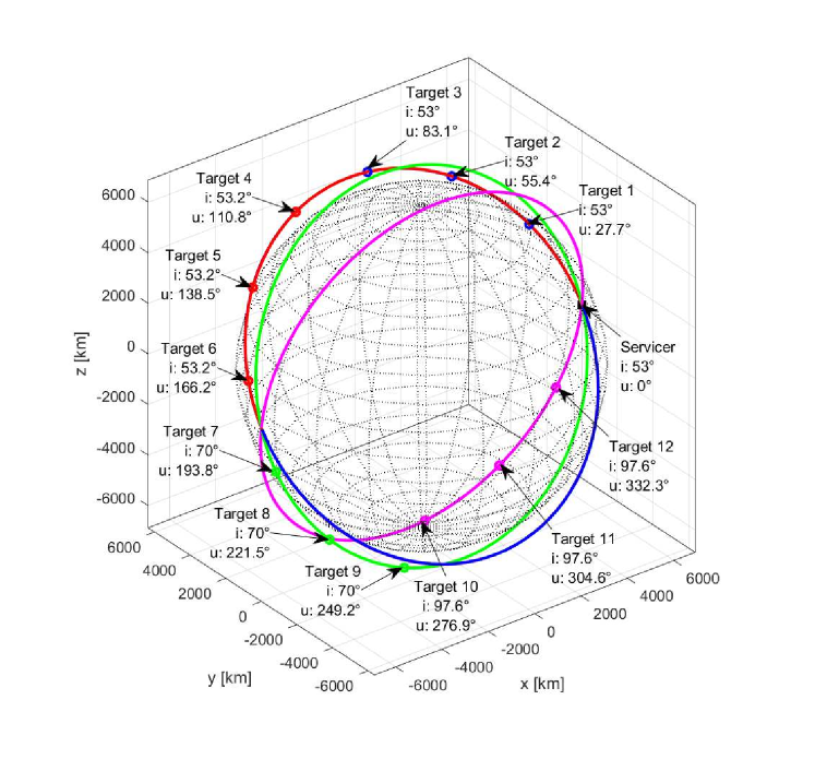
To compare cooperative and conventional non-cooperative on-orbit refueling architectures, simple multi-target refueling missions in LEOs are considered in this paper. The target spacecraft are assumed to be deployed in multiple orbital planes with different inclination angles (i.e., 53°, 53.2°, 70°, or 97.6° inspired by Starlink satellites). We assume that all of these orbits are circular with an altitude of 550 km, and the targets share the same Keplerian orbital elements except for the inclination and the argument of latitude. Table 2 lists the parameters used in this case study, and Fig. 3 illustrates the initial positions of the targets and the servicer considered in the Earth-Centered Inertial (ECI) frame. In this case study, the servicer separately refuels to Targets 1 to in Fig. 3.
| Parameter | Assumed value | |
| Constellation Parameters | ||
| number of targets | 1 - 12 | |
| initial inclination [deg] | 53, 53.2, 70, 97.6 | |
| initial argument of latitude | See Fig. 3 | |
| altitude [km] | 550 | |
| Refueling Mission Parameters | ||
| specific impulse of target [s] | 300 | |
| specific impulse of servicer [s] | 300 | |
| initial mass of each target [kg] | 1000 | |
| required refuel amount [kg] | 200 | |
To accomplish refueling to one target, either or both of the target and the servicer need to move to a rendezvous position. In this paper, we assume that these orbital transfers consist of two phases: inclination change and coplanar phasing. For circular orbits, the required to change the inclination, , is calculated as
| (16) |
where and denote the velocity of the circular orbit and the change in inclination, respectively. The required for phasing maneuvers, , is
| (17) |
where
| (18) | ||||
| (19) |
and denote the number of complete revolutions during the phasing by the servicer and the target, respectively, and denote the initial difference in the argument of latitude measured from the one that chases the other one. For the non-cooperative architecture, the servicer is always the one that chases the target, and in a cooperative architecture, it depends on their transfer strategies. Please refer to Refs. [33, 22] for the detailed derivation of Eq. (17).
This paper considers the following refueling architectures for the given LEO constellation:
-
A)
the conventional non-cooperative architecture where only the servicer actively conducts the orbital transfers;
-
B)
a cooperative architecture where the inclination change is done by the targets and the phasing is done by the servicer;
-
C)
a cooperative architecture where the inclination change is done by the servicer and the phasing is done by the targets;
-
D)
an architecture where all targets come to the servicer while the servicer remains in the same orbit (i.e., fully cooperative targets and passive servicer “depot”); and
-
E)
the optimal cooperative case that minimizes the initial mass of the servicer.
Figure 4 visually summarizes Architectures A-D. Architecture E can be any of Architectures A-D or an architecture where both the servicer and the targets conduct both the inclination change and phasing maneuvers if that can reduce the initial mass of the servicer further. Note that the order of the targets to be refueled is the same among all architectures. The consideration of the optimum of this order is left for future work.
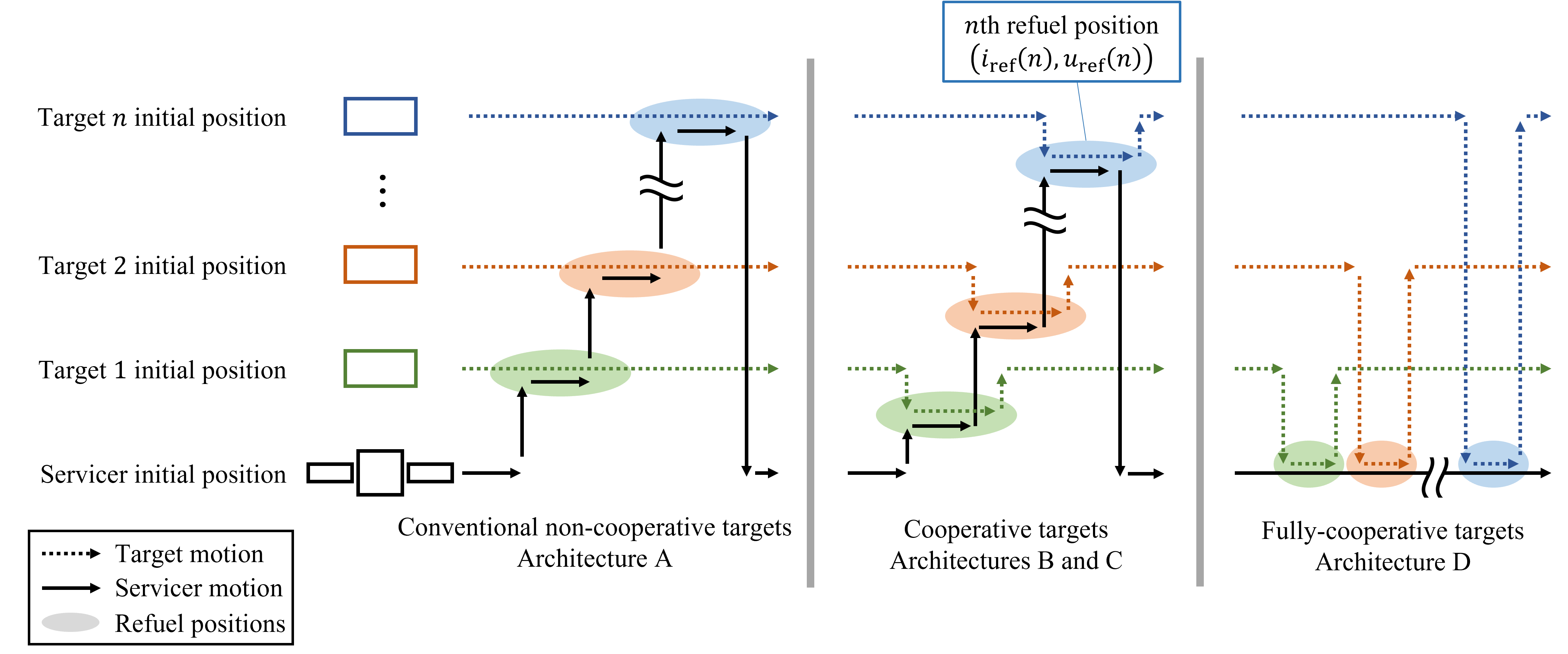
As mentioned above, we consider both the inclination change and the coplanar phasing for each orbital transfer for refueling. The inclination and the relative argument of latitude to the initial argument of latitude of the servicer where the th refuel is performed are denoted by and , respectively, and represent the initial inclination and the initial relative argument of latitude of Target , and and are those of the servicer. With this notation, each architecture has the following conditions:
-
A)
,
-
B)
,
-
C)
, and
-
D)
.
For Architecture E, and are the design variables for the optimization, i.e., there are design variables to be optimized. To find the optimal rendezvous points expressed by these parameters that minimize the initial mass of the servicer, , we use MATLAB’s MultiStart solver.
3.2 Results
3.2.1 Initial Mass of Servicer
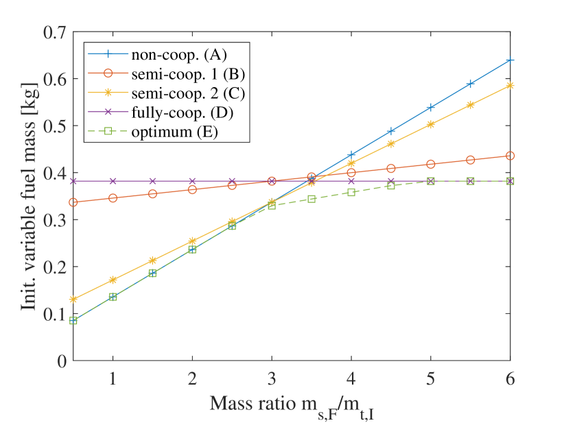
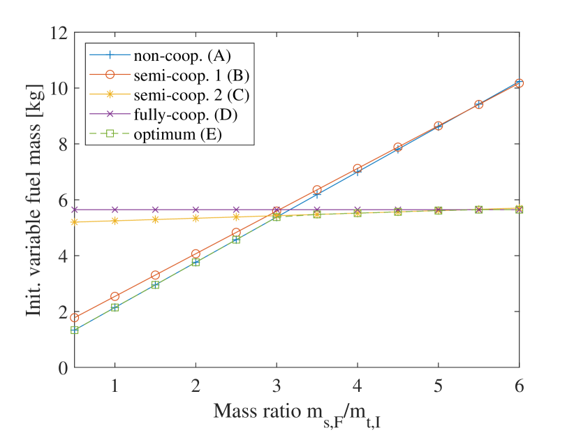
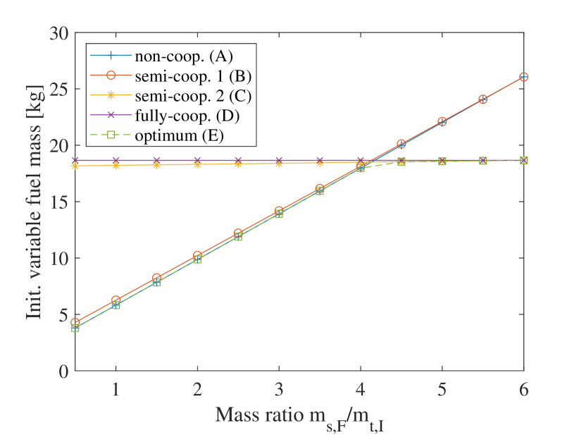
We first examine the initial mass of the servicer and particularly how it is impacted by the ratio between the final servicer mass (i.e., servicer dry mass) and the initial target mass (i.e., target mass before the entire refuel campaign), . The initial mass of the servicer is a summation of the following: dry mass, required refuel amount defined in this mission (i.e., ), consumed fuel mass by the servicer’s orbital transfer and the summation of consumed fuel mass by the targets’ orbital transfer . Note that, for Architecture A, , and for Architecture D, . Since the drymass and are fixed values between all architectures introduced in Sec. 3.1, we focused on the summation of and , the “variable fuel mass.”
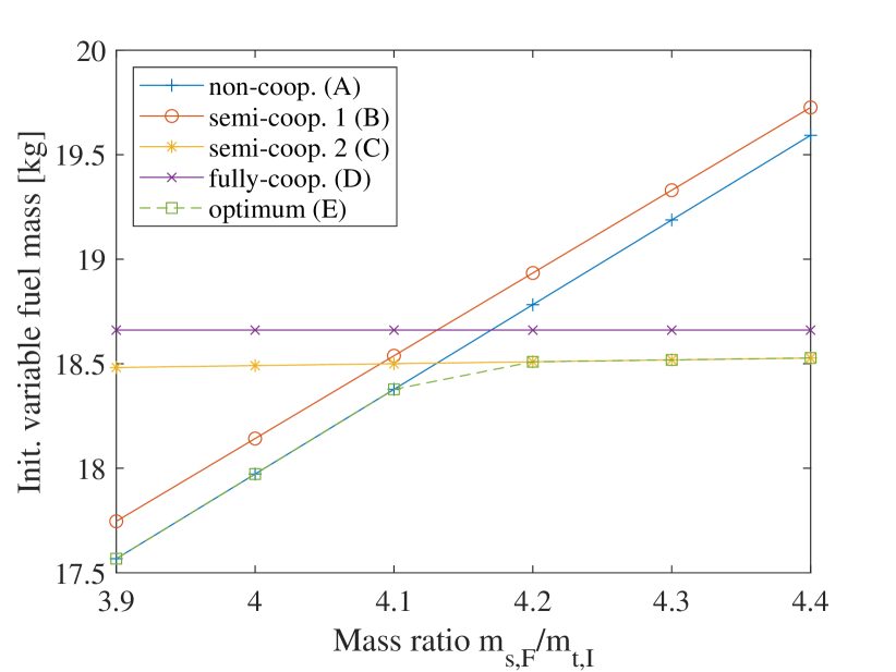
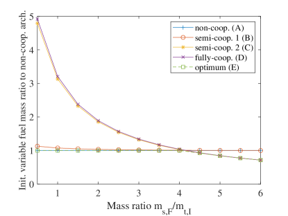
Fig. 5 compares the initial variable fuel mass in each mission architecture for given mass ratios for 6, 9, and 12. Note that means Targets 1 to in Fig. 3 are serviced. The points where the lines of Architecture A and any other architecture intersect are corresponding to the critical mass ratios . Fig. 5(d) shows the initial variable fuel mass of each Architecture for (Fig. 5(c)) around the critical mass ratio between Architectures A and D, (see more discussion on in Sec. 3.2.2). Since the servicer does not conduct any orbital transfer in Architecture D, the required variable fuel mass of Architecture D does not depend on the mass of the servicer. As discussed in Sec. 2.4, when the mass ratio is small (i.e., a light-weight servicer and heavy-weight targets), non-cooperative architecture (Architecture A) requires less fuel mass than the other cooperative architectures. Architecture D with fully cooperative targets requires the most fuel when the mass ratio is small; however, this architecture becomes the most beneficial when the mass ratio is large enough (i.e., a heavy-weight servicer and light-weight targets). Fig. 6 compares the initial variable fuel mass as a ratio to that of the non-cooperative Architecture A. As can be seen from this plot, cooperative architectures may require about five times larger amounts of variable fuel compared to the conventional Architecture A when the mass ratio is small while they can also reduce it by 30 % (or possibly more) when the mass ratio is large.
Furthermore, while Architecture E shows the optimal solution with the minimum fuel, this solution can be achieved by either of Architectures A-D in many conditions. In fact, except for the cases with and 3, 3.5, 4, or 4.5, the optimum architectures turned out to be identical to either Architecture A, C, or D in this case study. In addition, the observed optimum did not decrease the required fuel by a significant amount (see Fig. 5(a)). This result suggests that comparing Architectures A, C, and D are practically enough, especially when the mass ratio is small or large enough compared to the critical mass ratio . In other words, mission architects may not have to optimize their mission architecture in these cases.
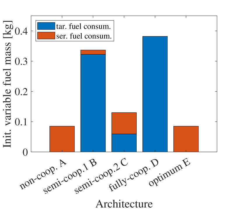
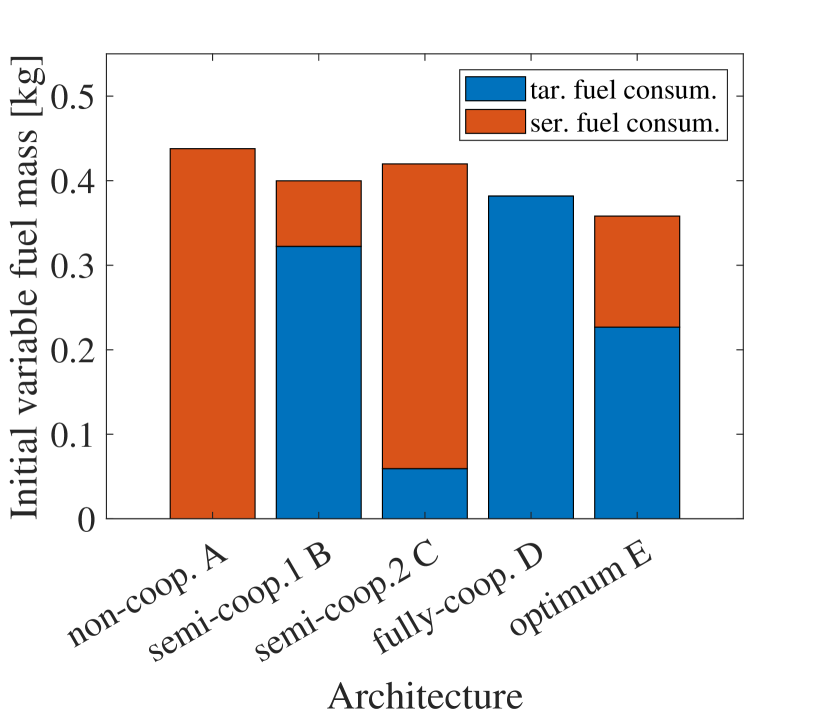
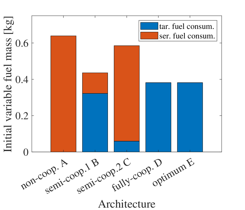
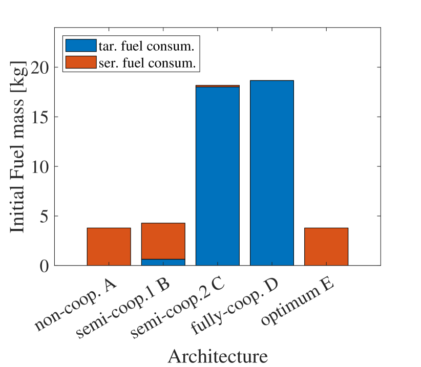
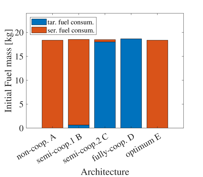
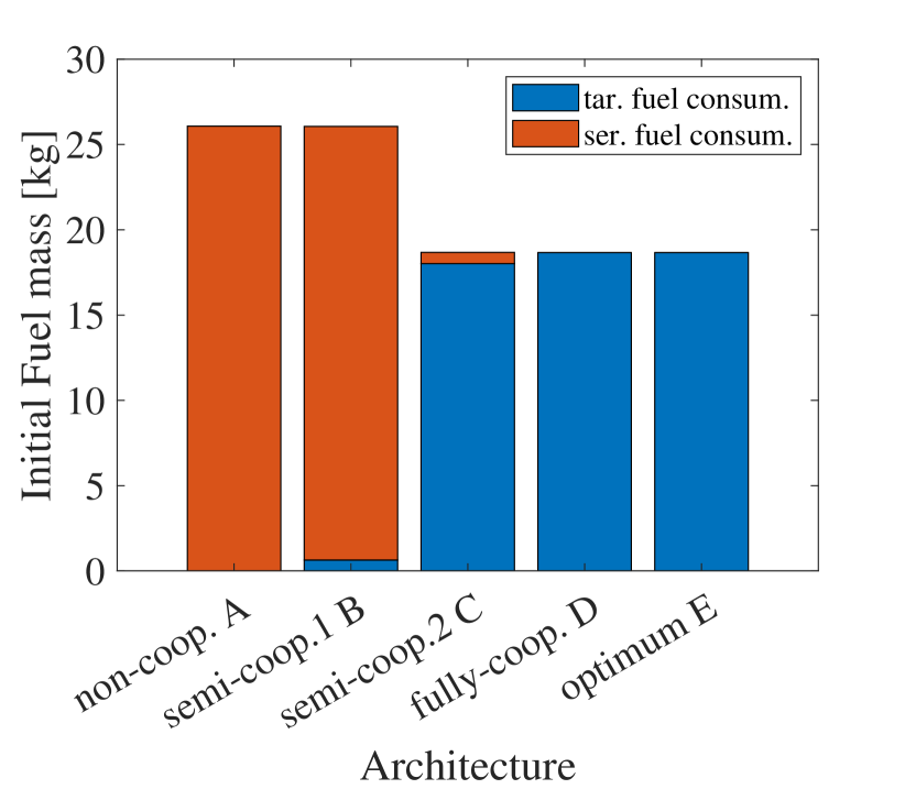
Bar charts Figs. 7 and 8 show the breakdown of the initial variable fuel mass of each Architecture with the different mass ratios for the cases of and 12. As can be seen from this figure, there’s a trade-off between the consumed fuel of the servicer and the targets. This can be particularly seen when focusing on the optimal case in Architecture E. When the servicer final mass is small (Figs. 7(a) and 8(a)), it is suggested that the servicer actively conducts orbital transfers as in Architecture A since it requires less fuel due to the mass difference between the servicer and the targets. On the other hand, the targets’ active transfers are recommended when the servicer is heavy (Figs. 7(c) and 8(c)). The difference in mass breakdown between Architectures B and C shown in each bar chart of Figs. 7 and 8 is due to the gap of the amount of required by inclination change and co-planner phasing maneuver. The relationship between Architectures B and C changes between these two different values of . For instance, Architecture B requires more fuel than C in Fig. 7(a) whereas Architecture C requires more in Fig. 8(a). This is because the required between the cases and 12 is significantly different due to the very large inclination difference for . This change in the relationship between these two Architectures can also be observed in Fig. 5 as the slope of each line.
3.2.2 Critical Mass Ratio
We next examine further the critical mass ratio, particularly the one that differentiates Architectures A and D. For Architecture D with fully cooperative targets, the servicer does not conduct any orbital transfer, i.e., . Therefore, from Inequality (LABEL:eq:mass_ineq2), the critical mass ratio that differentiates Architectures A and D, , can be calculated as
| (20) |
For each number of targets, is calculated using Eq. (20), and the results are shown in Fig. 9. When , becomes 1 suggesting whichever lighter between the servicer and Target 1 should move to save some fuel.
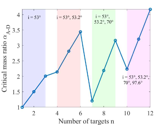
As can be seen in Fig. 9, linearly increases when the number of targets increases in the same orbital planes (see each colored area in this figure). When a new target in a different orbital plane is added, can decrease. For instance, there is a large drop between 6 and 7, and becomes close to 1.0 when . This is due to the large required for the refuel to Target 7. Fig. 10 compares Architecture A and D when . Since the required before and after the 7th refuel is significantly larger in both cases than that for other coplanar phasing maneuvers and inclination changes between and (see bold arrows in Fig. 10), these orbital transfers become the main mass driver. Since the difference between Architectures A and D regarding these transfers is rather small (i.e., to to for Architecture A, and to to for Architecture D), the critical mass ratio becomes close to 1.0. The behavior of the critical mass ratio is further discussed in Sec. 3.3.
3.3 Discussion and Sensitivity Analysis
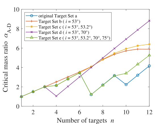
As previously mentioned in Sec. 3.2, Fig. 9 suggests that the critical mass ratio generally increases as the number of targets increases in the same orbital plane; however, it does not necessarily increase when the newly added targets are in a different orbital plane. To study this behavior, in this subsection, the sensitivity of inclination angles on the critical mass ratio is first examined by employing target sets where targets are distributed differently from Fig. 3. Table 3 lists target sets considered in this analysis and their inclination angles. Note that each target set has the same set of the argument of latitude values as the original Target Set a (see Fig. 3). These target sets are selected to explore the effects of multi-plane refueling compared to coplanar refueling (Target Set b and the other sets) and the large inclination change both near the initial orbit of the servicer (Target Sets c and d) and far from that (Target Sets a and e).
| Target # | 1-3 | 4-6 | 7-9 | 10-12 |
|---|---|---|---|---|
| a (original) | 53 | 53.2 | 70 | 97.6 |
| b | 53 | 53 | 53 | 53 |
| c | 53 | 53.2 | 53.2 | 53.2 |
| d | 53 | 70 | 70 | 70 |
| e | 53 | 53.2 | 70 | 75 |
Fig. 11 illustrates the behavior of the critical mass ratio in response to the change in with different target sets listed in Table 3. Since all targets in Target Set b are coplanar, the trend of this red line does not change even if all targets are in either , , or any other plane. As expected, large drops of occur when a new Target is added to a new plane that is far from the plane where the Target is initially located. On the other hand, this result suggests that when the newly-added plane of Target is close to the plane of the Target , the effect of adding a new plane becomes less significant. These behaviors can be observed by comparing the lines of Target Sets b, c, and d around and 4, and the lines of Target Sets a and e around and 10. A comparison of the lines of Target Sets c and d also suggests that the increment of the critical mass ratio becomes larger when the difference of inclination between the initial plane and the newly added plane is larger.
Furthermore, for the coplanar case (Target Set b), for and 12 are almost the same value. This is because the newly added Target 12 is located close to the original position of the servicer indicating that this orbit is becoming crowded with targets and adding one more target affects the entire refueling architectures less significantly. The line of Target Set c shows a similar trend: the slope of the Target Set c line becomes less steep around . This is because target set c is almost coplanar whereas the orbital planes of Target Sets a, d, and e are more scattered.
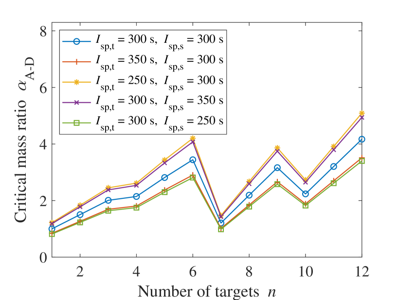
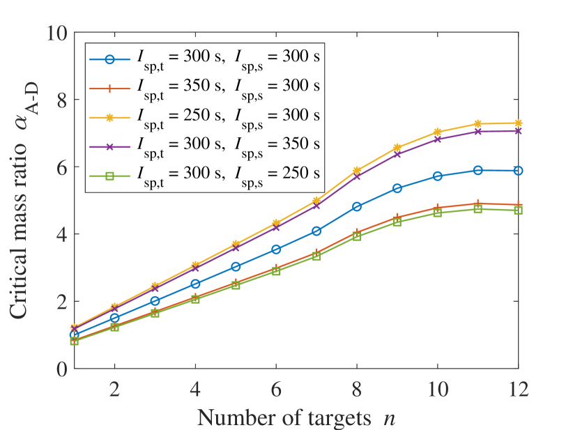
We also compare the effect of the specific impulse of the target () and the servicer (). Eq. (20) implies a smaller or a larger leads to a larger , and conversely, a larger or a smaller leads to a smaller . Fig. 12 shows the results of employing different values for both and for Target Set a (Fig. 12(a)) and Target Set b (Fig. 12(b)). As can be seen from this figure, the sensitivity of each specific impulse turned out to be about the same level between both target sets. Moreover, as expected from Eq. (20), increasing or decreasing reduces the critical mass ratio implying the fully-cooperative case can be favored with smaller servicer mass. On the other hand, smaller or larger makes the conventional non-cooperative architecture more favored. The sensitivities of and also turn out to be the same according to this figure. The investigation of the effect of employing electric propulsion is left for future work since the continuous orbital transfer significantly complicates the operation of this on-orbit refueling.
4 Conclusion
This paper developed an analytical model for non-cooperative and cooperative refueling architectures, and analytically derived the critical mass ratio that represents the break-even point between the two architectures. We further analyzed how mission parameters change this value through the case study of non-coplanar multi-target on-orbit refueling. If the ratio between the final servicer mass and the initial target mass, , is smaller than the critical mass ratio (a light-weight servicer and heavy-weight targets), the conventional non-cooperative architecture requires less fuel than the cooperative architecture. Conversely, if this ratio is larger than the critical mass ratio (a heavy-weight servicer with light-weight targets), employing the cooperative architecture may save some fuel. The result from the case study suggests this critical mass ratio generally increases as the number of targets increases in the same orbital plane. However, when new targets locate in different orbital planes, the critical mass ratio can also decrease depending on the difference in the inclination. The optimization of rendezvous inclination and the argument of latitude suggests that the saved fuel compared to non-cooperative architecture or fully-cooperative architecture is rather small. Hence, it may be sufficient to consider either of these architectures, especially for the initial mission design.
The extension of this study in spacecraft with low-thrust and high-specific-impulse propulsion (e.g., solar electric propulsion) is left for future work. The optimization of the order of spacecraft to be refueled and the study of the effect of refueling architecture on the order is another direction of future work. Different transfer techniques between each refuel such as solving Lambert’s problems should be discussed in the extension of this work, too.
Appendix
.1 Analytical Expression of Critical Mass Ratio
References
- Green et al. [1989] Green, C. G. B., Massatt, P. D., and Rhodus, N. W., “The GPS 21 Primary Satellite Constellation,” Navigation, Vol. 36, No. 1, 1989, pp. 9–24. https://doi.org/10.1002/j.2161-4296.1989.tb00978.x, URL https://onlinelibrary.wiley.com/doi/abs/10.1002/j.2161-4296.1989.tb00978.x.
- Foreman et al. [2017] Foreman, V. L., Siddiqi, A., and Weck, O. D., “Large Satellite Constellation Orbital Debris Impacts: Case Studies of OneWeb and SpaceX Proposals,” AIAA SPACE and Astronautics Forum and Exposition, 2017. 10.2514/6.2017-5200, URL https://arc.aiaa.org/doi/abs/10.2514/6.2017-5200.
- Boshuizen et al. [2014] Boshuizen, C., Mason, J., Klupar, P., and Spanhake, S., “Results from the planet labs flock constellation,” 28th Annual AIAA/USU Conference on Small Satellites, 2014.
- Lee et al. [2020] Lee, H. W., Shimizu, S., Yoshikawa, S., and Ho, K., “Satellite Constellation Pattern Optimization for Complex Regional Coverage,” Journal of Spacecraft and Rockets, Vol. 57, No. 6, 2020, pp. 1309–1327. 10.2514/1.A34657, URL https://doi.org/10.2514/1.A34657.
- Anderson et al. [2022] Anderson, J. F., Cardin, M.-A., and Grogan, P. T., “Design and analysis of flexible multi-layer staged deployment for satellite mega-constellations under demand uncertainty,” Acta Astronautica, Vol. 198, 2022, pp. 179–193. https://doi.org/10.1016/j.actaastro.2022.05.022, URL https://www.sciencedirect.com/science/article/pii/S0094576522002181.
- Roy et al. [2021] Roy, D. P., Huang, H., Houborg, R., and Martins, V. S., “A global analysis of the temporal availability of PlanetScope high spatial resolution multi-spectral imagery,” Remote Sensing of Environment, Vol. 264, 2021, p. 112586. https://doi.org/10.1016/j.rse.2021.112586, URL https://www.sciencedirect.com/science/article/pii/S0034425721003060.
- Cornara et al. [1999] Cornara, S., Beech, T., Belló-Mora, M., and Martinez de Aragon, A., “Satellite constellation launch, deployment, replacement and end-of-life strategies,” 13th Annual AIAA/USU Conference on Small Satellites, 1999.
- Jakob et al. [2019] Jakob, P., Shimizu, S., Yoshikawa, S., and Ho, K., “Optimal Satellite Constellation Spare Strategy Using Multi-Echelon Inventory Control,” Journal of Spacecraft and Rockets, Vol. 56, No. 5, 2019, pp. 1449–1461. 10.2514/1.A34387, URL https://doi.org/10.2514/1.A34387.
- Luu and Hastings [0] Luu, M. A., and Hastings, D. E., “On-Orbit Servicing System Architectures for Proliferated Low-Earth-Orbit Constellations,” Journal of Spacecraft and Rockets, Vol. 0, No. 0, 0, pp. 1–20. 10.2514/1.A35393, URL https://doi.org/10.2514/1.A35393.
- Hall and Papadopoulos [1999] Hall, E., and Papadopoulos, M., “GPS structural modifications for on-orbit servicing,” Space Technology Conference and Exposition, 1999. 10.2514/6.1999-4430, URL https://arc.aiaa.org/doi/abs/10.2514/6.1999-4430.
- Long et al. [2007] Long, A. M., Richards, M. G., and Hastings, D. E., “On-Orbit Servicing: A New Value Proposition for Satellite Design and Operation,” Journal of Spacecraft and Rockets, Vol. 44, No. 4, 2007, pp. 964–976. 10.2514/1.27117, URL https://doi.org/10.2514/1.27117.
- Hatty [2022] Hatty, I., “Viability of On-Orbit Servicing Spacecraft to Prolong the Operational Life of Satellites,” Journal of Space Safety Engineering, Vol. 9, No. 2, 2022, pp. 263–268. https://doi.org/10.1016/j.jsse.2022.02.011, URL https://www.sciencedirect.com/science/article/pii/S2468896722000131.
- Inaba and Oda [2000] Inaba, N., and Oda, M., “Autonomous satellite capture by a space robot: world first on-orbit experiment on a Japanese robot satellite ETS-VII,” Proceedings 2000 ICRA. Millennium Conference. IEEE International Conference on Robotics and Automation. Symposia Proceedings (Cat. No.00CH37065), Vol. 2, 2000, pp. 1169–1174 vol.2. 10.1109/ROBOT.2000.844757.
- Ogilvie et al. [2008] Ogilvie, A., Allport, J., Hannah, M., and Lymer, J., “Autonomous robotic operations for on-orbit satellite servicing,” Sensors and Systems for Space Applications II, Vol. 6958, edited by R. T. Howard and P. Motaghedi, International Society for Optics and Photonics, SPIE, 2008, p. 695809. 10.1117/12.784081, URL https://doi.org/10.1117/12.784081.
- Oda [1999] Oda, M., “Space robot experiments on NASDA’s ETS-VII satellite-preliminary overview of the experiment results,” Proceedings 1999 IEEE International Conference on Robotics and Automation (Cat. No.99CH36288C), Vol. 2, 1999, pp. 1390–1395 vol.2. 10.1109/ROBOT.1999.772555.
- Northrop Grumman [2020] Northrop Grumman, “Intelsat 901 Satellite Returns to Service Using Northrop Grumman’s Mission Extension Vehicle,” https://news.northropgrumman.com/news/releases/intelsat-901-satellite-returns-to-service-using-northrop-grummans-mission-extension-vehicle, Apr 2020. Accessed: 2022-11-09.
- Northrop Grumman [2021] Northrop Grumman, “Northrop Grumman and Intelsat Make History with Docking of Second Mission Extension Vehicle to Extend Life of Satellite,” https://news.northropgrumman.com/news/releases/northrop-grumman-and-intelsat-make-history-with-docking-of-second-mission-extension-vehicle-to-extend-life-of-satellite, Apr 2021. Accessed: 2022-11-09.
- Bourjolly et al. [2006] Bourjolly, J.-M., Gurtuna, O., and Lyngvi, A., “On-orbit servicing: a time-dependent, moving-target traveling salesman problem,” International Transactions in Operational Research, Vol. 13, No. 5, 2006, pp. 461–481. https://doi.org/10.1111/j.1475-3995.2006.00558.x, URL https://onlinelibrary.wiley.com/doi/abs/10.1111/j.1475-3995.2006.00558.x.
- Meng et al. [2019] Meng, B., Huang, J., Li, Z., Huang, L., Pang, Y., Han, X., and Zhang, Z., “The orbit deployment strategy of OOS system for refueling near-earth orbit satellites,” Acta Astronautica, Vol. 159, 2019, pp. 486–498. https://doi.org/10.1016/j.actaastro.2019.02.001, URL https://www.sciencedirect.com/science/article/pii/S0094576518313882.
- Shen et al. [2018] Shen, H.-X., Zhang, T.-J., Casalino, L., and Pastrone, D., “Optimization of Active Debris Removal Missions with Multiple Targets,” Journal of Spacecraft and Rockets, Vol. 55, No. 1, 2018, pp. 181–189. 10.2514/1.A33883, URL https://doi.org/10.2514/1.A33883.
- Sarton du Jonchay and Ho [2017] Sarton du Jonchay, T., and Ho, K., “Quantification of the responsiveness of on-orbit servicing infrastructure for modularized earth-orbiting platforms,” Acta Astronautica, Vol. 132, 2017, pp. 192–203. https://doi.org/10.1016/j.actaastro.2016.12.021, URL https://www.sciencedirect.com/science/article/pii/S009457651630741X.
- Sarton du Jonchay et al. [2021] Sarton du Jonchay, T., Chen, H., Gunasekara, O., and Ho, K., “Framework for Modeling and Optimization of On-Orbit Servicing Operations Under Demand Uncertainties,” Journal of Spacecraft and Rockets, Vol. 58, No. 4, 2021, pp. 1157–1173. 10.2514/1.A34978, URL https://doi.org/10.2514/1.A34978.
- Sarton du Jonchay et al. [2022] Sarton du Jonchay, T., Chen, H., Isaji, M., Shimane, Y., and Ho, K., “On-Orbit Servicing Optimization Framework with High- and Low-Thrust Propulsion Tradeoff,” Journal of Spacecraft and Rockets, Vol. 59, No. 1, 2022, pp. 33–48. 10.2514/1.A35094, URL https://doi.org/10.2514/1.A35094.
- Ho et al. [2020] Ho, K., Wang, H., DeTrempe, P. A., du Jonchay, T. S., and Tomita, K., “Semi-Analytical Model for Design and Analysis of On-Orbit Servicing Architecture,” Journal of Spacecraft and Rockets, Vol. 57, No. 6, 2020, pp. 1129–1138. 10.2514/1.A34663, URL https://doi.org/10.2514/1.A34663.
- Shen and Tsiotras [2005] Shen, H., and Tsiotras, P., “Peer-to-Peer Refueling for Circular Satellite Constellations,” Journal of Guidance, Control, and Dynamics, Vol. 28, No. 6, 2005, pp. 1220–1230. 10.2514/1.9570, URL https://doi.org/10.2514/1.9570.
- Salazar and Tsiotras [2006] Salazar, A., and Tsiotras, P., “An auction algorithm for allocating fuel in satellite constellations using peer-to-peer refueling,” 2006 American Control Conference, 2006, pp. 6 pp.–. 10.1109/ACC.2006.1657380.
- Dutta and Tsiotras [2008] Dutta, A., and Tsiotras, P., “Egalitarian Peer-to-Peer Satellite Refueling Strategy,” Journal of Spacecraft and Rockets, Vol. 45, No. 3, 2008, pp. 608–618. 10.2514/1.31299, URL https://doi.org/10.2514/1.31299.
- Dutta and Tsiotras [2010] Dutta, A., and Tsiotras, P., “Network Flow Formulation for Cooperative Peer-to-Peer Refueling Strategies,” Journal of Guidance, Control, and Dynamics, Vol. 33, No. 5, 2010, pp. 1539–1549. 10.2514/1.45570, URL https://doi.org/10.2514/1.45570.
- Dutta et al. [2012] Dutta, A., Arora, N., and Russell, R. P., “Peer-to-Peer Refueling Strategy Using Low-Thrust Propulsion,” Journal of Spacecraft and Rockets, Vol. 49, No. 5, 2012, pp. 944–954. 10.2514/1.A32106, URL https://doi.org/10.2514/1.A32106.
- Du et al. [2015] Du, B., Zhao, Y., Dutta, A., Yu, J., and Chen, X., “Optimal scheduling of multispacecraft refueling based on cooperative maneuver,” Advances in Space Research, Vol. 55, No. 12, 2015, pp. 2808–2819. https://doi.org/10.1016/j.asr.2015.02.025, URL https://www.sciencedirect.com/science/article/pii/S0273117715001362.
- Zhao et al. [2017] Zhao, Z., Zhang, J., yang Li, H., and yong Zhou, J., “LEO cooperative multi-spacecraft refueling mission optimization considering J2 perturbation and target’s surplus propellant constraint,” Advances in Space Research, Vol. 59, No. 1, 2017, pp. 252–262. https://doi.org/10.1016/j.asr.2016.10.005, URL https://www.sciencedirect.com/science/article/pii/S0273117716305658.
- Cox et al. [2022] Cox, S. A., Stastny, N. B., Droge, G. N., and Geller, D. K., “Resource-Constrained Constellation Scheduling for Rendezvous and Servicing Operations,” Journal of Guidance, Control, and Dynamics, Vol. 45, No. 7, 2022, pp. 1202–1212. 10.2514/1.G006153, URL https://doi.org/10.2514/1.G006153.
- Vallado [2013] Vallado, D. A., Fundamentals of Astrodynamics and Applications, 4th ed., Microcosm Press, California, 2013.