Stable radiation field positron acceleration in a micro-tube
Nowadays, there is a desperate need for an ultra-acceleration-gradient method for antimatter particles, which holds great significance in exploring the origin of matter, CP violation, astrophysics, and medical physics. Compared to traditional accelerators with low gradients and a limited acceleration region for positrons in laser-driven charge separation fields, we propose an innovative high-gradient positron acceleration mechanism with implementation advantages. Injecting a relativistic electron beam into a dense plasma micro-tube generates a stable and periodic high-intensity mid-infrared radiation (mid-IR) field, reaching tens of . This field, propagating synchronously with the electron beam, achieves a 1 energy gain for the positron bunch within 140 picoseconds with a minimal energy spread—approximately 1.56 during a stable phase. By utilizing continuous mid-IR, the efficiency of energy transfer from the electron beam to either a single positron bunch or three positron bunches simultaneously could reach up to 20 and 40, respectively. This acceleration scheme can achieve cascaded acceleration for a single positron bunch and series acceleration for multiple positron bunches in a continuous, stable, and efficient manner.
1 Introduction
The high-efficiency particle acceleration technology holds unique importance in astroparticle physics, medical physics, and material sciences[1, 2, 3]. Traditional accelerators are limited by the ionization threshold of materials[4, 5], typically reaching gradients of around hundreds of . Therefore, to obtain high-energy particle beams, larger accelerator facilities are required, leading to increased costs. Laser and particle beam-driven plasma charge separation wakefields can generate higher acceleration gradients, typically ranging from several tens to several hundreds of , while allowing control over the energy spread and beam emittance of the accelerated particles[6, 7, 8, 9, 10, 11, 12]. Significant progress has been made in electron beam acceleration in this regard. Simultaneously, various positron acceleration schemes are continuously being proposed. The fundamental plasma bubble acceleration, driven by a laser or an electron beam[13, 14, 15, 16, 17, 18, 19], results in positrons undergoing a shorter acceleration phase in comparison to electron plasma acceleration, which can lead to instability. Concurrently, strong transverse forces can also diminish the quality of the positron beam. Therefore, the concept of electron beam driving within a hollow plasma channel is proposed, aiming to achieve longitudinally stable acceleration for positrons[20, 21, 22, 23]. For proton beam driven acceleration, there is an increase in particle divergence due to the strong Coulomb force, with additional four-stage iron focusing guidance applied to the hollow channel[24]. When considering the driving of electron beams, the density of the hollow plasma channel has a different effect on positron acceleration. Positron acceleration in low-density channels occurs during the phase formed between the first and second bubbles. Addressing the stability of the acceleration phase and the preparation of the given-density plasma channel is challenged.
Ultra-short electron beams passing through the copper film target interface generate strong coherent transition radiation (CTR), which can be used to capture and accelerate positron beams produced through the Bethe-Heitler (BH) process in the target[25]. Additionally, the issues of radiation and electron beam divergence are suggested to be solved by strengthening the magnetic field and using a proper waveguide[26]. Simultaneously, single-cycle tunable infrared pulses generated in density-tailored plasma can be used to drive the acceleration of positrons[27, 28]. In this paper, we propose a novel mechanism based on the continuous emission of high-intensity mid-infrared radiation (mid-IR). This radiation is generated by the oscillations of surface-nanometer electron films driven by a relativistic electron beam in a plasma and/or metal micro-tube. This method allows for the construction of a highly efficient and stable uniform field structure. The stable wavelength of the periodic acceleration field is approximately 24 in the mid-IR range, and it can be tuned by adjusting the micro-tube radius, for example, into the terahertz range. The acceleration field can reach several tens of and depends on the charge of the driving electron beam. For an electron beam with a charge of several tens of , the acceleration field can even reach several hundreds of , resulting in positron acceleration energy gains ranging from tens to hundreds of .
The self-consistent fields of a relativistic electron beam in a plasma micro-tube and the high-intensity continuous mid-IR generated by surface-nanometer film-plasma oscillations were analyzed. Field validation was performed by injecting a positron witness bunch. The results indicate that positrons can achieve energy gains at the GeV level within 140 , with an achievable energy spread of up to 1.56 and an efficiency of up to 20. The quality of the positron beam can be adjusted by modifying the driving parameters, allowing for positron energies ranging from to even hundreds of . In the uniform mid-IR acceleration field, the transverse field () focuses the positron bunch within the first 21 , followed by weak defocusing until the transverse field reduces to zero due to energy loss and beam break of the electron beam. Through several 2-dimensional particle-in-cell (PIC) simulations, the transverse spatial misalignment of positron injection was allowed to be a few microns if a 10 relative loss in energy transfer efficiency is acceptable, where the accelerated energy and energy spread are hardly affected. The design scheme for cascaded acceleration of a single positron bunch and series acceleration of multiple positron bunches is presented in the ’Discussion’ section.
2 Analysis of acceleration process
2.1 Self-fields of relativistic beam in a plasma micro-tube
For a relativistic electron beam propagating in the direction in free space with a normalized velocity and a density distribution , the initial current is given as . The relativistic Poisson’s equation in the laboratory frame can be written as [29, 30, 31]
| (1) |
where is the Lorentz factor of the relativistic electron beam, and is the electrostatic potential. To solve the initial potential in free space, the standard fast Fourier transformation (FFT) algorithm is used to perform the cosine transform. Therefore, the electric fields of the initial electron beam can be computed as . Due to the factor, the longitudinal electric field has a much smaller magnitude than the transverse electric field .
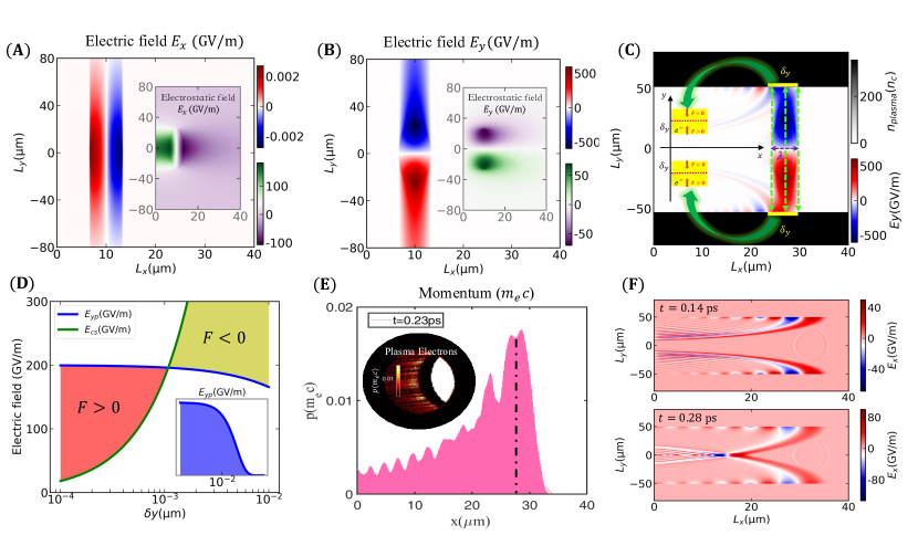
In this study, the initial electric field distribution was obtained through a PIC simulation for a Gaussian electron bunch with a charge of 3.402 and a Lorentz factor of corresponding to an electron beam energy of 1 . Detailed parameters can be found in the Methods section. The initial and of the relativistic electron beam are shown in Figs. 1(A) and (B), respectively, with their subplots displaying the generated electrostatic fields. In the case of a plasma micro-tube with a radius of 50 , the of the relativistic electron beam was applied to the inner walls due to its larger value (approximately 200 ) compared to that of a static electron bunch. The field decays exponentially as it passes through the dense plasma film (now denoted as ), and can be expressed as
| (2) |
where is the radius of the plasma micro-tube, is the penetration depth of the electric field in the plasma, and is the charge separation distance. The plasma frequency was calculated as , which is approximately , where is the density of dense plasma micro-tube. The longitudinal length of the electron beam was fixed at , and the normalization parameter was set as , where . A strong charge separation field proportional to the separation distance , expressed as
| (3) |
Fig. 1(C) displays the distribution of within a dense plasma micro-tube with a radius of 50 . The resultant force for this setup is given an . For , the electron film was pushed back and forth between regions of and to realize the oscillation of the surface-nanometer film - plasma electrons. Fig. 1(D) displays the distribution of the electric field and the charge separation field within the dense plasma micro-tube. For the surface-nanometer electron film with , the resultant force nullifies, and the plasma electrons gain the maximum momentum.
2.2 High-intensity mid-IR acceleration field
The resultant force applied by the electric field and the charge-separation field within the dense plasma causes oscillations of the surface-nanometer electron film, moving in and out of the inner-surface. The energy of these electrons can be obtained as
| (4) |
where is the Lorentz factor of the plasma electrons, and is electron mass. For , is computed to be 1.0002, and the normalized electron velocity in the plasma, , is computed to be 0.0206. Fig. 1(E) shows the momentum distribution of the oscillating electrons from the PIC simulation. Only the electrons on the surface-nanometer film gain kinetic energy. As the electron beam passes through, the oscillations weaken, and the velocity decreases. Initially, the surface-nanometer electron film starts to oscillate and emit continuous mid-IR radiation. The electric field radiated through the oscillations of an electron, , is then obtained as
| (5) |
where and is the angle between the solid angle direction and . For the interaction region, the total electric field is then calculated through the 3-dimensional integration with the micro-tube density as
| (6) |
where is the longitudinal radiation field, is the distance from the reference point to the micro-tube wall, and .
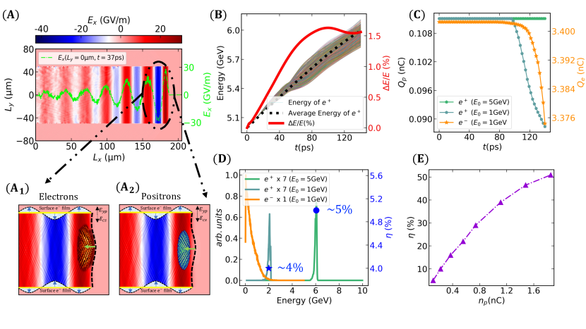
Using Eq. (6), the total radiation field was obtained for different parameter ranges. For example, with , we obtained . Fig. 1(F) shows the radiation field distribution in the plasma micro-tube obtained from the PIC simulation at and , respectively. The radiation field produced by the oscillations of the electron film propagates from the inner wall to the center to catch up with the driving electron beam. Therefore, in Fig. 2(A), a high intensity acceleration field is formed in a stable TM mode with a mid-IR wavelength of 24 . The relevant characteristics of the mid-infrared field inside the micro-tube have been discussed in reference [28], including radiation intensity, wavelength, micro-tube radius, and so on.
2.3 Results of beam acceleration
As the relativistic electron beam propagates in the micro-tube, the continuous mid-IR evolves into a high-intensity stable period structure of the longitudinal acceleration field in Fig. 2(A). Figs. 2(A1) and (A2) provide a magnified view of the first period region and the phase of the electrons and positrons. The acceleration of the positron bunch in the dense plasma micro-tube was observed and analyzed through PIC simulations.
We analyzed the relationship between positron acceleration time, positron energy, and relative energy spread in Fig. 2(B). The positron bunch gains an energy increase of 1 within 140 picoseconds, with a relative energy spread of . Fig. 2(C) shows the decrease in the total charge of the electron beam and two cases of positron bunches (with initial energies of and , both having a beam charge of ) during the acceleration process. In Fig. 2(D), the final energy spectrum of positron bunches with different initial energies and the electron beam at is displayed.
The energy transfer efficiency from the driving electron beam to the positron bunch is defined as , where represents the change in the energy of the electron or positron bunch, and is the charge of the electron beam or positron bunch. The energy transfer efficiency was approximately and for positron bunches with initial energies of GeV and GeV, respectively. The energy transfer efficiency, , increased with the initial charge of the positron bunch, , and even reached up to for nC, as shown in Fig. 2(E).
The acceleration field exhibits a stable period distribution, with the field intensity and stabilization time being correlated with the charge and energy of the driving electron beam. We can adjust the parameters of the injected electron and positron beams to meet various application requirements: (1) A positron beam with an initial energy of 50 can be accelerated to several within 140 using a driving electron beam with 1 and 3 . (2) The acceleration mechanism allows for cascaded acceleration, enabling the positron beam to achieve higher energy levels under less demanding initial conditions. (3) Positrons undergoing acceleration over a one-meter with a 45 driving electron beam can gain an energy increase of 100 .
2.4 Evolution of transverse electromagnetic fields
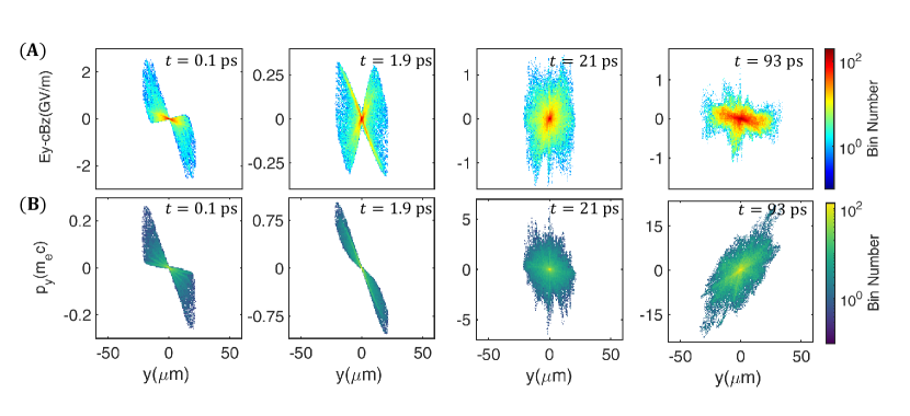
The stable acceleration of the positron bunch is achieved using the high-intensity longitudinal acceleration field generated by the oscillation of surface-nanometer electron film in the plasma micro-tube. Simultaneously, the transverse self-field generated by the relativistic electron beam also provides a transverse focusing force to the positron bunch. The transverse fields in the y- and z-directions, specifically, and , were symmetrically configured in the PIC simulation.
Fig. 3(A) displays the transverse field distribution of the positron bunch at , , , and . In the early stage of the longitudinal acceleration ( ), the transverse force remains focused. After , the transverse field becomes uniform at the edges, and the positron bunch remains stable in the transverse direction for several tens of picoseconds. Beyond 21 , the field gradually weakens and becomes weakly defocused as the energy of the electron beam is consumed. Fig. 3(B) shows the corresponding phase-space distribution of the positron bunch, corresponding to the transverse field distribution in Fig. 3(A). Therefore, the analysis of the transverse field distribution and the transverse motion of the positron bunch in the y-direction revealed an initial weak focusing stage, followed by a weak defocusing stage, until the magnitudes of the transverse fields reduced to zero.
2.5 Transverse off-axis bunch injection
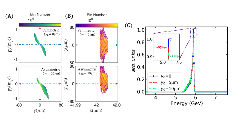
The proposed scheme enables stable and efficient acceleration of an externally injected positron bunch. Given the uniformity of the acceleration field, experimental misalignment of the injected positron bunch is inevitable but allowed within specific regions. To determine acceptable misalignment, several 2-dimensional PIC simulations were conducted with varying transverse injection deviations from the central axis. The simulations used the following key parameters: electron beam longitudinal and transverse lengths of and , respectively, with a number density of ; positron bunch longitudinal and transverse lengths of and , with a number density of 7 ; and initial injection positions of the positron bunch at 0, 5, and 10 . Other simulation parameters were the same as those of the cylindrical coordinate simulations mentioned in the Methods section. Fig. 4(A) shows the asymmetric phase-space distribution of a positron bunch with a positive y-axis deviation compared to the symmetric one. Fig. 4(B) shows the density distribution of the positron bunch in the plane after a long period of acceleration in both the asymmetric and symmetric cases. Due to the initial injection deviation in the y-direction, although the phase-space distribution of the positron bunch maintains this asymmetry during the acceleration process, the central energy and the energy spread of the accelerated positron bunch are hardly affected in the uniform longitudinal acceleration field. Fig. 4(C) displays the influence of the different transverse injection misalignments ( 0, 5, and 10 ) on the accelerated energy spectrum of positron bunch. In each case, the positron bunch gained the same amount of energy at a given time . However, the difference was the peak charge at the central energy which affects the energy transfer efficiency of the accelerated positron bunch; it decreases by for the deviation of 10 relative to that without deviation. Therefore, the excellent tolerance for the injection deviation of the positron bunch greatly reduces the implementation difficulty of the experiment.
3 Dicussions
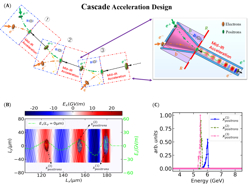
In our model, the density of the plasma micro-tube was fixed to be of the same order as the free-electron density in metals. Therefore, we propose a similar application of the method in metal micro-tubes. The transverse self-field of the relativistic electron beam (several hundreds of ) can directly ionize the surface of the metal micro-tube. It can also interact with the space-separation field to drive the oscillation of the ionized electron film, and the production of high-intensity, continuous mid-IR. This high-efficiency scheme has a high acceleration gradient and stable acceleration structure, and can also realize cascaded acceleration, allowing for a stable, continuous, and efficient positron acceleration. Fig. 5(A) displays the cascade design schematic diagram illustrating the acceleration of a positron bunch by electron beams, demonstrating a three-step acceleration process. The driving electron beam is extracted to the trash after completing a single acceleration. A cone-shaped coupling tube surrounded by a magnetic field. For a magnetic field of and initial energy of 1 of the electron or positron bunch, the deflection radius of particle bunch () was computed as . After setting the deflection angle to for , the positron bunch was accelerated for in a mid-IR acceleration field through the micro-tube to obtain a energy gain. Due to the stable periodic structure of the mid-IR acceleration field in the micro-tube, the series acceleration can also be considered to obtain multiple high-energy positron bunches at the same time. This process is demonstrated by the 2-dimensional PIC simulation (Fig. 5(B)) of the acceleration field driven by a single electron beam in a micro-tube, accelerating three positron bunches, , , and , simultaneously, starting from initial positions of , , and , respectively. The final energy spectrum of the positron bunches is shown in Fig. 5(C) with the initial energy of . The energy transfer efficiency was found to be about 2-3 times higher than that of a single positron bunch acceleration. For an injected positron bunch with a long longitudinal dimension, such as 20 , at a phase of , where the front and rear of the positron bunch are in an accelerating phase, and the center is in a decelerating phase. During long-distance propagation, the positrons in the central portion will be decelerated to the second acceleration phase. This allows the single bunch to split into two separate bunches for subsequent individual acceleration.
4 Conclusion
In this paper, we proposed a novel scheme for the acceleration of positron bunches using high-intensity, continuous mid-IR field. The injected positron bunch could gain energy of after accelerating for a distance of , and could maintain a low energy spread of . The energy transfer efficiencies () for two positron bunches with a charge of and were observed to be and , respectively. In the uniform mid-IR acceleration field, the transverse field in the -direction () weakly focused on the positron bunch within the first , post which it began weakly defocusing, till it finally reduced to zero due to the energy loss and beam break of the driving electron beam. The ease of performing the experiment was increased due to the excellent tolerance of the positron bunch injection deviation. Through several 2-dimensional PIC simulations, the transverse spatial misalignment of the positron injection is allowed to be a few microns if relative loss of the energy transfer efficiency is accepted, where the accelerated energy and the energy spread are hardly affected. The novel high-efficiency scheme had a high acceleration gradient and a stable acceleration structure, allowing for a stable, efficient, and continuous acceleration of multiple positron bunches simultaneously.
5 Methods
The proposed scheme is confirmed by cylindrical geometry with a decomposition in azimuthal modes using the SMILEI code[32], which is an open-source, user-friendly, high-performance and multi-purpose electromagnetic particle-in-cell (PIC) code for plasma simulation. The grid coordinates are two-dimensional , while particle coordinates are expressed in the three-dimensional Cartesian frame . A moving window of 51.2 in the direction and 100 in the direction was employed, which was sampled by 512 cells in the direction and 400 cells in the direction. Electromagnetic boundary conditions were implemented using the Perfectly Matched Layer (PML) to absorb fields at the boundary. Additionally, a binomial filter module was applied to the currents to reduce noise. The plasma critical number density is for the . The density of the dense plasma is with the radius of 50 and the thickness of 30 . The initial energy of the driving electron bunch is 1 , with a 3.402 beam charge. The initial momentum is Maxwell-Juttner distribution with temperature 0.1 in the x directron and 0.001 in the y and z direction. The density profile of the electron bunch is a Gaussian distribution in the x and r direction, , where , , longitudinal rms-length , transverse rms-length . The witness positron bunch has an initial energy of 5 or 1 and a beam charge of 0.111 . The density of the positron bunch is with longitudinal rms-length , transverse rms-length , and the initial positron is 33.5 . The initial energy spread, angular distribution and the normalized emittances of the positron bunch is neglected. There are 20 macro-particles per cell (PPC) for the driving electron bunch and the witness positron bunch, and 4 PPC for the plasma species. The results have been compared with PPC=50 for particles bunch and PPC=4/100/200/400 for the plasma particles of micro-tube, which are almost no difference. The analysis of transverse off-axis injection of positron bunch and series acceleration of multiple positron bunches are simulated with 2-dimensions PIC. A moving window of 204.8 () 160 () is used and sampled by 2048 640 cells.
Acknowledgments
Funding: This work is supported in part by National Natural Science Foundation of China (11655003); Innovation Project of IHEP (542017IHEPZZBS11820, 542018IHEPZZBS12427); the CAS Center for Excellence in Particle Physics (CCEPP); IHEP Innovation Grant (Y4545170Y2); Chinese Academy of Science Focused Science Grant (QYZDY-SSW-SLH002); Chinese Academy of Science Special Grant for Large Scientific Projects (113111KYSB20170005); National 1000 Talents Program of China; the National Key Research and Development Program of China (No.2018YFA0404300); National Natural Science Foundation of China (Grant No. 11975252); Youth Innovation Promotion Association CAS (No. 2021012).
Author contributions: M.Y.S. contributed to investigation, validation, formal analysis, data curation, simulation, writing—original draft. Y.S.H. contributed to conceptualization, methodology, formal analysis, supervision, project administration, funding acquisition, writing—review and editing. M.Q.R. contributed to formal analysis. B.F.S. contributed to formal analysis. Z.L.X. helped in formal analysis. T.P.Y. helped in formal analysis, writing—review and editing. X.F.W. contributed to formal analysis. Y.C. contributed to formal analysis.
Competing interests:The authors declare no conflicts of interest.
Data and materials availability: This manuscript has no associated data or the data will not be deposited.
References
References
- [1] L. Marchut, C. J. Mcmahon, Electron and positron spectroscopies in materials science and engineering. Electron Positron Spectroscopies in Materials Science Engineering, 1–33 (1979).
- [2] Guessoum, Nidhal, Positron astrophysics and areas of relation to low-energy positron physics. European Physical Journal D 68, 1-6 (2014).
- [3] K. R. Hogstrom, P. R. Almond, Review of electron beam therapy physics. Physics in Medicine, Biology 51, R455 (2006).
- [4] E. Gschwendtner, P. Muggli, Plasma wakefield accelerators. Nature Reviews Physics 1, 246-248 (2019).
- [5] X. J. Jiao, J. M. Shaw, T. Wang et al, A tabletop, ultrashort pulse photoneutron source driven by electrons from laser wakefield acceleration. Matter and Radiation at Extremes 2, 296-302 (2017).
- [6] T. Tajima, J. M. Dawson, Laser electron accelerator. Physical Review Letters 43, 267 (1979).
- [7] Katsouleas, Thomas, Electrons hang ten on laser wake. Nature 431, 515-516 (2004).
- [8] J. Faure, Y. Glinec, A. Pukhov et al, A laser–plasma accelerator producing monoenergetic electron beams. Nature 431, 541-544 (2004).
- [9] S. P. Mangles, C. D. Murphy, Z. Najmudin et al, Monoenergetic beams of relativistic electrons from intense laser–plasma interactions. Nature 431, 535-538 (2004).
- [10] C. G. R. Geddes, C. Toth, J. Van Tilborg et al, High-quality electron beams from a laser wakefield accelerator using plasma-channel guiding. Nature 431, 538-541 (2004).
- [11] Wang, J., Zeng, M., Li, D., Wang, X., Lu, W., Gao, J, Injection induced by coaxial laser interference in laser wakefield accelerators. Matter and Radiation at Extremes 7, 054001 (2022).
- [12] Dai, Y. N., Shen, B. F., Li, J. X., Shaisultanov, R., Hatsagortsyan, K. Z., Keitel, C. H., Chen, Y. Y. , Photon polarization effects in polarized electron–positron pair production in a strong laser field. Matter and Radiation at Extremes 7, 014401 (2022).
- [13] T. J. Xu, B. F. Shen et al, Ultrashort megaelectronvolt positron beam generation based on laser-accelerated electrons. Physics of Plasmas 23, 033109 (2016).
- [14] X. L. Zhu, M. Chen, T. P. Yu et al, Collimated GeV attosecond electron–positron bunches from a plasma driven by 10 PW lasers. Matter and Radiation at Extremes 4, 014401 (2019).
- [15] K. V. Lotov, Acceleration of positrons by electron beam-driven wakefields in a plasma. Physics of Plasmas 14, 023101 (2007).
- [16] C. Du, Z. Xu, Positron acceleration by a laser pulse in a plasma. Physics of Plasmas 7, 1582-1585 (2000).
- [17] H. Hasegawa, S. Usami, Y. Ohsawa, Positron acceleration to ultrarelativistic energies by a shock wave in a magnetized electron–positron–ion plasma. Physics of Plasmas 10, 3455-3458 (2003).
- [18] X. Wang, R. Ischebeck et al, Positron Injection and Acceleration on the Wake Driven by an Electron Beam in a Foil-and-Gas Plasma. Physical Review Letters 101, 124801 (2008).
- [19] J. Vieira, J.T. Mendonça, Nonlinear laser driven donut wakefields for positron and electron acceleration. Physical Review Letters 112, 215001(2014).
- [20] C. B. Schroeder, D. H. Whittum, J. S. Wurtele, Multimode analysis of the hollow plasma channel wakefield accelerator. Physical Review Letters 82, 1177 (1999).
- [21] C. B. Schroeder et al, Beam loading in a laser-plasma accelerator using a near-hollow plasma channel. Physics of Plasmas 20, 123115 (2013).
- [22] S. Gessner, E. Adli et al, Demonstration of a positron beam-driven hollow channel plasma wakefield accelerator. Nature communications 7, 1-6 (2016).
- [23] S. Zhou, J. Hua et al, High efficiency uniform wakefield acceleration of a positron beam using stable asymmetric mode in a hollow channel plasma. Physical Review Letters 127, 174801(2021).
- [24] L. Yi, B. Shen et al, Positron acceleration in a hollow plasma up to TeV regime. Scientific Reports 4, 4171 (2014).
- [25] Z. Xu, L. Yi et al, Driving positron beam acceleration with coherent transition radiation. Communications Physics 3, 191 (2020).
- [26] Xu, Z., Shen, B., Si, M., Huang, Y. S.. Positron acceleration by terahertz wave and electron beam in plasma channel. New Journal of Physics (2023).
- [27] Zhu, X. L., Liu, W. Y., Weng, S. M., Chen, M., Sheng, Z. M., Zhang, J, Generation of single-cycle relativistic infrared pulses at wavelengths above 20 from density-tailored plasmas. Matter and Radiation at Extremes 7, 014403 (2022).
- [28] Meiyu Si, Yongsheng Huang, Manqi Ruan, Baifei Shen, Zhangli Xu, Tongpu Yu, Xiongfei Wang, and Yuan Chen, ”Relativistic-guided stable mode of few-cycle 20 level infrared radiation,” Optics. Express 31, 40202-40209 (2023).
- [29] P. Londrillo, C. Gatti, M. Ferrario, Numerical investigation of beam-driven PWFA in quasi-nonlinear regime. Nuclear Instruments and Methods in Physics Research Section A: Accelerators, Spectrometers, Detectors and Associated Equipment 740, 236-241 (2014).
- [30] F. Massimo, A. Marocchino, A. R. Rossi, Electromagnetic self-consistent field initialization and fluid advance techniques for hybrid-kinetic pwfa code architect. Nuclear Instruments and Methods in Physics Research Section A: Accelerators, Spectrometers, Detectors and Associated Equipment 829, 378-382 (2016).
- [31] A. Marocchino, E. Chiadroni et al, Design of high brightness Plasma Wakefield Acceleration experiment at SPARC-LAB test facility with particle-in-cell simulations. Nuclear Instruments and Methods in Physics Research Section A: Accelerators, Spectrometers, Detectors and Associated Equipment 909, 408-413 (2018).
- [32] J. Derouillat et al, SMILEI: A collaborative, open-source, multi-purpose particle-in-cell code for plasma simulation. Computer Physics Communications 222, 351-373 (2017).