Asynchronous Trajectory Matching-Based Multimodal Maritime Data Fusion for Vessel Traffic Surveillance in Inland Waterways
Abstract
The automatic identification system (AIS) and video cameras have been widely exploited for vessel traffic surveillance in inland waterways. The AIS data could provide the vessel identity and dynamic information on vessel position and movements. In contrast, the video data could describe the visual appearances of moving vessels, but without knowing the information on identity, position and movements, etc. To further improve vessel traffic surveillance, it becomes necessary to fuse the AIS and video data to simultaneously capture the visual features, identity and dynamic information for the vessels of interest. However, traditional data fusion methods easily suffer from several potential limitations, e.g., asynchronous messages, missing data, random outliers, etc. In this work, we first extract the AIS- and video-based vessel trajectories, and then propose a deep learning-enabled asynchronous trajectory matching method (named DeepSORVF) to fuse the AIS-based vessel information with the corresponding visual targets. In addition, by combining the AIS- and video-based movement features, we also present a prior knowledge-driven anti-occlusion method to yield accurate and robust vessel tracking results under occlusion conditions. To validate the efficacy of our DeepSORVF, we have also constructed a new benchmark dataset (termed FVessel) for vessel detection, tracking, and data fusion. It consists of many videos and the corresponding AIS data collected in various weather conditions and locations. The experimental results have demonstrated that our method is capable of guaranteeing high-reliable data fusion and anti-occlusion vessel tracking.
Index Terms:
Inland waterways, vessel traffic surveillance, deep neural network, anti-occlusion tracking, data fusion.I Introduction
The autonomy and intelligence of the inland waterways surveillance system play a significant role in the development of inland waterborne transportation, which can effectively reduce the labor cost of the supervisory departments and ensure the safety of vessel navigation. To accomplish this objective, the vessel traffic service (VTS) system is capable of providing effective situational awareness by using the automatic identification system (AIS), radar, closed circuit television (CCTV) [1], etc. To further increase the capability of situational awareness, many intelligent technologies for single sensor have been presented, e.g., AIS-based vessel trajectory prediction [2], radar-based object detection [3], and video-based object detection [4]. It is well known that each type of sensor has its own advantages and disadvantages under the same scenarios. As a consequence, numerous efforts have been devoted to simultaneously exploiting the multi-source data [1, 5, 6, 7, 8, 9] to promote the traffic situational awareness for maritime transportation systems. However, these fusion methods mainly just take into consideration the positional relationship of the same target at a certain moment. It thus becomes difficult to guarantee high-quality data fusion, especially for the existence of time delay, missing data, random outliers, etc. The same moving vessels essentially share similar navigation behaviors, which could be represented using the time-series data, e.g., spatio-temporal trajectories. To further improve the stability and accuracy of data fusion, we will first extract the vessel trajectories from the raw sensing data, and then propose a trajectory matching-based fusion method (termed DeepSORVF) in this work.
I-A Motivation and Contribution
Owing to the remote, intuitive, and real-time advantages of CCTV, terrestrial video surveillance systems have been widely used in inland waterborne transportation to improve the ability of traffic situational awareness and vessel abnormal behavior monitoring[10]. In particular, massive monitoring cameras can provide indispensable visual information for guaranteeing maritime safety. To fully use these visual features, many efforts have focused on the research of vessel detection and tracking to meet the requirement of intelligent supervision [11, 12, 13]. However, these methods could only detect the moving vessel from the video images. It is intractable to achieve the important identity information (e.g., vessel name and size, etc.) and dynamic information (e.g., vessel speed and course, etc.).
Other maritime awareness equipment, such as AIS and radar, could provide much richer attribute information about the vessel. In particular, the AIS data contains rich vessel identity and spatio-temporal information, which makes it play an essential role in analyzing vessel abnormal behaviors. The AIS data mainly contains the static and dynamic information, e.g., maritime mobile service identification (MMSI), vessel size, speed, course, position, etc. However, the AIS data essentially suffers from the inconsistency of time intervals, which limits its application in maritime intelligent transportation [14]. The radar has been widely used in near port supervision since it can provide the accurate distance and bearing of vessels. Unfortunately, some radar equipment is forbidden to be installed in populated regions to avoid the high-frequency electromagnetic radiation harming the health of people [1]. In the literature [15], many methods have been proposed to robustly and accurately fuse the AIS and radar data. As long we simultaneously collect the AIS, radar, and video data, we can directly adopt the existing advanced methods to fuse the AIS and radar data, and then implement fusion with the video data. Intuitively, the fusion of AIS and video data seems more difficult because of the different coordinate systems, asynchronous data collection, different data structures, etc. Therefore, we tend to only fuse the AIS and video data to enhance the traffic situational awareness for intelligent surveillance in inland waterways.
In this work, we propose a deep learning-based simple online and real-time vessel data fusion method (termed DeepSORVF) for promoting inland waterways surveillance. The main contributions of this work are as follows:
-
•
We build two simple yet efficient methods to respectively extract the AIS- and video-based vessel trajectories for data fusion. To avoid the interference of vessel occlusion on video-based trajectory extraction, we propose a prior knowledge-driven anti-occlusion tracking method.
-
•
We design a novel asynchronous trajectory matching method to achieve the robust fusion of AIS and video data. The proposed method adopts an enhanced fast dynamic time warping algorithm for trajectory similarity measure and employs an AIS/video association method to decrease the computational cost and increase the stability.
-
•
We construct a public benchmark dataset (termed FVessel) for vessel detection, tracking, and data fusion, which consists of many videos and the corresponding AIS data collected in various weather conditions and locations.
To our best knowledge, our DeepSORVF is the first trajectory matching-based computational method to fuse the AIS and video data for inland waterways surveillance. Meanwhile, we have verified the effectiveness and robustness of the proposed method on our newly-developed FVessel dataset.
I-B Organization
The rest of this paper is organized as follows. Section II briefly reviews the recent research on object detection, tracking, AIS and video data fusion. In Section III, the proposed data fusion framework is described in detail. Section IV implements extensive comprehensive experiments to demonstrate the effectiveness of our method. Finally, Section V summarizes the main contributions of this work.
II Related Works
This section mainly introduces the recent studies related to our work, i.e., multi-object detection and tracking, AIS and video data fusion.
II-A Multi-Object Detection and Tracking
Multi-object detection and tracking methods are generally divided into two categories, namely traditional and deep learning methods. Due to the particularity of the research issue, this section mainly reviews the related works on vessel detection and tracking.
II-A1 Traditional Methods
Background subtraction (BS) is a classic object detection method. Although many BS-based methods are proposed to detect conventional objects, these methods still achieve poor precision in vessel detection [16]. To improve the precision of the BS-based method, Hu et al. [17] designed a robust foreground detection and background update method to effectively reduce the influence of waves. Bloisi et al. [18] proposed an independent multi-modal background subtraction (IMBS) algorithm. In particular, this algorithm models highly dynamic backgrounds (e.g., water) by creating a “discretization” of an unknown distribution. Furthermore, other types of vessel detection methods are proposed. For instance, Zhu et al. [19] designed a hierarchical complete-based vessel detection approach for spaceborne optical images. Zhang et al. [20] proposed a vessel detection algorithm using the discrete cosine transform (DCT)-based Gaussian mixture model (GMM) for efficient visual maritime surveillance on non-stationary surface platforms. Chen et al. [21] achieved the vessel object tracking using multi-view learning and sparse representation. Although many techniques have been introduced to improve the performance of detectors, hand-designed features still produce poor robustness in vessel detection. Meanwhile, the high computational complexity of some methods will hinder their practical applications.
II-A2 Deep Learning Methods
With the emergence and rapid development of graphics processing units (GPU), deep learning technology is widely used in the field of image processing. Many deep learning methods are proposed for object detection, e.g., region-based convolutional neural network (R-CNN) [22, 23], single shot multibox detector (SSD) [24, 25], and you only look once network (YOLO) [26, 27, 28, 29]. Based on these object detection networks, many vessel detection methods are further researched. Shao et al. [30] proposed a YOLOv2-based saliency-aware network for vessel detection, which combined the salient features and coastline features to predict more accurate vessel positions. Liu et al. [12] built an enhanced YOLOv3 network to promote vessel detection in video-based maritime surveillance. To reduce the impact of poor weather environments on vessel detection, this method constructed a data enhancement strategy to improve vessel detection precision in low-light, hazy, and rainy images. Furthermore, Chen et al. [31] proposed a small vessel detection method based on an improved generative adversarial network (GAN) and a convolutional neural network (CNN). Feng et al. [4] proposed a ship detection method based on the multi-size gradient features and multi-branch support vector machine (SVM). Yang et al. [32] applied the visual object tracking and semi-supervised object segmentation to the vessel tracking task, and proposed an enhanced SiamMask network.
II-B AIS and Video Data Fusion
In current literature, many AIS and video data fusion methods have been proposed. For instance, Chen et al. [5] proposed a single-vessel tracking method by combining AIS and video data. In particular, this method could make the camera focus on the vessel according to the position information provided by the AIS, and use the Kalman filter to ensure the smoothness of the tracking. However, the operator fails to accurately obtain the identities and attributes of each vessel when the field of view exists multiple vessels. Therefore, more researchers began to focus on the information fusion of multiple vessels. For instance, Man et al. [6] fused the AIS and video data with the Kalman filter to obtain the optimal vessel trajectory. Bloisi et al. [1] proposed an automated maritime surveillance system that replaces radar sensors with vision sensors, which can be deployed in densely populated regions. Lu et al. [7] proposed a vision and AIS fusion method, which estimated the distance and azimuth of the detected visual vessel from the camera and fused it with the position information in the AIS data. Huang et al. [8] designed a novel multi-vessel tracking technology based on the improved single shot multi-box detector (SSD) [24] and DeepSORT [33] algorithm, and used a multi-modal data fusion algorithm to display the AIS information of visual targets. Recently, Liu et al. [9] constructed an intelligent edge-enabled shipboard navigation system based on augmented reality, deep object detection, and multi-source data fusion technologies. This system can achieve stable vessel detection under various complex weather conditions and fuse the detected vessel targets with synchronized AIS information.
III DeepSORVF: Deep Learning-based Simple Online and Real-time Vessel Data Fusion
In this section, the details of our method will be introduced. Fig. 1 displays the flowchart of our data fusion method, including AIS-based vessel trajectory extraction, video-based vessel trajectory extraction, and asynchronous vessel trajectory matching. For the AIS data, we perform data cleaning and delayed data prediction to obtain high-quality AIS data. To guarantee that the AIS and video data are in the same coordinate system, we use the pinhole model to project the AIS data to the pixel coordinate system. For the video data, we first use the YOLOX network to detect vessel targets. To avoid the impact of vessel occlusion on the video-based trajectory, a prior knowledge-driven anti-occlusion tracking method is then used for video-based vessel trajectory extraction. During trajectory matching, we adopt the enhanced fast dynamic time warping algorithm (E-FastDTW) to calculate the similarity between trajectories and combine the Hungarian algorithm to obtain the matching results. It is worth mentioning that the matching result will be input into the video-based vessel trajectory extraction task at the next moment as prior knowledge. Based on our matching results, the AIS information (including, MMSI, longitude, latitude, speed, course, heading, etc.) and the visual vessel can be easily fused to facilitate inland waterways surveillance.
III-A AIS-Based Vessel Trajectory Extraction
The AIS is widely used in maritime services since it can provide the integrated and rich vessel information. However, due to the limitation of the AIS working principle, AIS data fails to be required in real-time. Meanwhile, some abnormal and redundant AIS information will affect the accuracy and robustness of AIS-based trajectory extraction. Furthermore, the matching of these two data becomes increasingly difficult since AIS- and video-based trajectories are, respectively, in the WGS-84 and pixel coordinate systems. Therefore, we tend to extract the AIS-based trajectory projected in the pixel coordinate system for data fusion. To achieve this goal, we first process the AIS data to generate high-quality AIS data. Subsequently, the AIS-based vessel trajectory will be obtained by the pinhole model.
III-A1 AIS Data Processing
Fig. 2 displays our framework for processing AIS data. The historically processed AIS data and the AIS data received at the current moment are combined as the input. The input data is successively processed by data cleaning, data prediction, and data re-cleaning to obtain high-quality AIS data as output. The data cleaning process is used to delete the AIS data outside the supervision region and abnormal data including the missing and abnormalities of the latitude, longitude, heading, speed, and MMSI. The data prediction module can estimate the position of vessels that have not yet received AIS information. Let be the speed of the vessel at time , the moving distance at the time interval can be expressed as . According to the longitude , latitude , and course at time , and the moving distance at time interval , the longitude and latitude at time can be generated by the forward geodetic computations111We exploit the pyproj.Geod.fwd function to implement the forward geodetic computations..
III-A2 Vessel Positioning via Coordinate Transformation
To fuse the high-quality AIS information and visual object, it is necessary to unify the different source data into the same coordinate system. In this work, we tend to project the AIS information in the world coordinate system (WCS) to the pixel coordinate system (PCS). Before the coordinate transformation, we first perform a Mercator projection on the original position of the AIS information. Let be the real vessel position in the 3D WCS, its 2D projection coordinate in PCS can be obtained by
| (1) |
with being the scale factor. Here, and are the internal and external parameter matrices of the camera, respectively. In this work, since the camera is fixed, we set the extrinsic parameter matrix as an identity matrix. In particular, we directly use the pinhole model to estimate . Please refer to Ref. [34] for more details on the internal parameter estimation. Finally, we sequentially save the AIS data with the same MMSI into the same list in time series to build a set of all AIS-based vessel trajectories with and being the -th AIS trajectory and the number of AIS-based vessel trajectories.
III-B Video-Based Vessel Trajectory Extraction
Although many methods have been proposed to achieve vessel detection and tracking [4, 35, 36], it is still intractable to extract high-quality video-based vessel trajectories for data fusion. In the actual application of video-based maritime surveillance, the inevitable occlusion between vessels occurs in the cross encounter, confrontation, and chasing situations. Generally, it becomes difficult to accurately and robustly detect these vessels under the occlusion condition. Meanwhile, the corresponding appearance will be seriously affected by other vessels. To improve the quality of extracted trajectories, we propose a prior knowledge-driven anti-occlusion tracking method, as shown in Fig. 3.
Specifically, we first adopt the YOLOX network to detect the visual vessel object and get a set of bounding boxes, i.e.,
| (2) |
where is the location of the -th bounding box, denotes the number of bounding boxes.
Before the tracking, the results of the previous moment are input as the prior knowledge. Firstly, a set of the occlusion areas OAR will be used, which depends on the ratio of the occlusion area to the bounding boxes. The judgment metric of the occlusion area can be expressed as follows
| (3) |
where is the area of the occluded part, is the area of the -th occluded bounding box, is the number of occluded bounding boxes, represents the anti-occlusion threshold. When the ratio exceeds , we will store the location of the smallest rectangle box AR which can contain all occluded bounding boxes into the OAR. Meanwhile, the AIS-based vessel trajectories at the current moment and the video-based vessel trajectories at the previous moment are also used as prior information, which can be given by
| (4) |
where and represent the trajectory series of the -th AIS target and the -th visual target, respectively, and are the numbers of AIS- and video-based vessel trajectories, respectively. Besides, we consider the AIS/video association results at the previous moment and the vessel appearance embedding before the occlusion, which can be given by
| (5) |
where means that the -th AIS target and -th visual target are successfully associated, is the appearance embedding of the -th visual target before occlusion222The vessel appearance embedding is extracted by the wide residual network [37] in the DeepSORT.. We will detailedly describe the generation of AIS/video association results in Section III-C.
For the anti-occlusion tracking, the detection results located in the occlusion area OAR are removed to avoid the mis-detection caused by the vessel overlapping. Based on the fusion results at the previous moment, the corresponding AIS information of the occluded visual vessel is available. Therefore, the location of the occluded vessel’s bounding box at the current moment can be estimated by
| (6) |
where and are the pixel indexes of the top-left and bottom-right points of the previous bounding box, respectively, and are the horizontal and vertical motion speeds, which are equal to the displacement of the AIS information between the current and previous moments.
For the occluded vessels without the corresponding AIS information, the bounding box will be predicted via the visual motion features. The prediction result can also be given by variants based on Eq. (6). The horizontal and vertical motion speeds (, ) are replaced with the visual trajectory-based horizontal and vertical motion speeds (, ), which can be calculated by
| (7) |
where and denote the points of the video-based vessel trajectory at the previous moment and the previous moment, respectively.
After prediction, we will then update the OAR and . Based on the predicted detection box position, the occlusion area list OAR will be updated via Eq. (3) for the anti-occlusion tracking at the next moment. For the update of , we first set up the occluded visual target as . If exists in the original , we directly store into the new ; otherwise, the appearance embedding of at the previous moment will be stored in the new . Then, we employ a wide residual network to extract the vessel appearance embedding in normal bounding boxes, and assign the vessel appearance embedding before occlusion in the to occluded bounding boxes. Finally, the bounding boxes and the corresponding vessel appearance embedding are jointly input into the DeepSORT for generating the video-based vessel trajectories at the current moment .
It is worth mentioning that two metrics in DeepSORT can solve the ID assignment issue. Firstly, the Mahalanobis distances between the predicted Kalman states and the newly arrived locations are calculated as the location similarity metrics. Moreover, the cosine distances between the appearance embedding are calculated as the appearance similarity metrics. In our method, the appearance features of the occluded vessels are kept consistent with the latest extractions before the occlusion. Therefore, as long as the predicted bounding box is close to the prediction of Kalman filters, the ID of occluded vessels will not be assigned incorrectly. The pseudo code of the proposed anti-occlusion tracking method is shown in Algorithm 1.
III-C Asynchronous Vessel Trajectory Matching
In this section, we propose a simple yet effective trajectory matching method to fuse the AIS- and video-based asynchronous vessel trajectories. Firstly, we adopt an enhanced fast dynamic time warping (E-FastDTW) algorithm considering the direction to calculate the similarity of AIS- and video-based vessel trajectories. Based on the similarity measure result, the Hungarian algorithm is employed to generate the optimal matching result. To improve the stability and robustness of data fusion and reduce the computational cost, we employ an AIS/video association mechanism. When the number of successful pairings of two trajectories exceeds a pre-determined threshold, the AIS- and video-based vessel trajectories will be associated directly without similarity evaluation.
III-C1 Trajectory Similarity Measure via E-FastDTW
For trajectory-based data fusion, it is an important prerequisite to determine the similarities between the AIS- and video-based vessel trajectories. The Euclidean distance is a simple but effective similarity calculation method. However, it requires that the two trajectories to be matched have the same length. Meanwhile, the Euclidean distance considers that two similar trajectories with only a slight shift in the time axis are significantly different. Therefore, dynamic time warping (DTW) has been proposed for ignoring this shift [38]. Suppose we have two trajectories and of length and respectively, represented as
| (8) |
Based on the two trajectories, the DTW constructs a alignment matrix where is the Euclidean distance between the points and . Then, a warp path is defined to construct the mapping between and , which can be written by
| (9) |
with being the length of , and . In particular, the warp path has three restrictions. For the sake of better understanding, we define the -th and the -th elements of as and . These three constraints for warp path can be defined as follows:
-
•
Restriction 1: The -st and the -th elements of are and , respectively.
-
•
Restriction 2: The adjacent elements of the warp path can only contain the adjacent coordinate points, including the diagonal adjacent. Therefore, the can only be one of .
-
•
Restriction 3: The elements of the warp path are monotonically increasing in time, i.e., and .
Under the premise of satisfying the above three constraints, DTW only focuses on the path with the minimum cumulative distance of alignment matrix elements corresponding to all points [38]. Meanwhile, the included angle between the starting and ending points of and is also considered. Finally, the similarity value between and calculated by our proposed E-FastDTW can be written as follows
| (10) |
where is the Euclidean distance between two data points corresponding to the -th element in the warp path , denotes the sum of all in the warp path . To find the desired unique warp path, the DTW adopts the dynamic programming strategy. The cumulative distance between and is the sum of the minimum cumulative distance of three previous possible warp path elements and the Euclidean distance between the points and , which can be mathematically written as
| (11) | ||||
Furthermore, we also adopt the multi-level approach used in the FastDTW to speed up the time series similarity search and reduce the computational complexity. Please refer to Ref. [39] for more details on the multi-level approach.
III-C2 Trajectory Matching
In this work, we propose a novel matching method with higher precision and less computation. In particular, we will match and associate the AIS-based vessel trajectories mentioned in Section III-A, and the video-based vessel trajectories mentioned in Section III-B, which can be defined as follows
| (12) |
where and represent the trajectories of the -th AIS target and the -th visual target , respectively, and are the numbers of AIS- and video-based vessel trajectories, respectively. Furthermore, the numbers of AIS/video matches and association results at the previous moment are also considered as input, i.e.,
| (13) |
where is the number of successful matches of and , means that and have been associated together. In the similarity measure, it is obviously time-consuming and intractable to adopt the E-FastDTW for calculating the similarity between all trajectories at each moment. Inspired by the DeepSORT algorithm, we propose a trajectory association mechanism to solve these issues. In particular, if two trajectories have been recorded in the , the two trajectories are directly matched by default without similarity measurement with other trajectories. Subsequently, we perform the similarity measure between all trajectories and construct a similarity matrix of size , where represents the similarity value of and . In particular, when the Euclidean distance between the last trajectory points of and exceeds the maximum matching distance , we consider the two trajectories to be completely different and set . When the binding trajectory pair exists in the , we set and set the values of other horizontal and vertical positions to positive infinity. For other ordinary trajectory pairs that do not satisfy the above conditions, we employ Eq. (10) (i.e., E-FastDTW) to calculate the trajectory similarity. After obtaining the similarity matrix , we adopt the Hungarian optimization algorithm to find the optimal matching result , which contains the matching trajectory pair information, i.e.,
| (14) |
where means that and are matched together. Then, we will generate the AIS/video matching results and association results at the current moment. More specifically, we iterate through all matching trajectory pairs in the . If the number of matching times of trajectory pair in the exists in the , we will store to ; otherwise, 1 will be stored to . In addition, we save the number of matching times for some trajectory pairs directly from into . These need to satisfy two conditions, which can be defined as follows:
-
•
must exist in but is not in .
-
•
The time interval between the last matching moment and the current moment is less than .
For the generation of the AIS/video association result, we set a minimum number of matches as a threshold to ensure that the association information is accurate. When in the is greater than , we will store into . The pseudo code of the proposed trajectory matching method is shown in Algorithm 2.
| Video | Video Length | Type | Weather | TOO | NOV | NOA |
|---|---|---|---|---|---|---|
| video-01 | 10m07s | Bridge | Low-light | 2 | 5 | 4 |
| video-02 | 19m52s | Bridge | Sunny | 6 | 7 | 6 |
| video-03 | 19m14s | Riverside | Sunny | 6 | 5 | 5 |
| video-04 | 06m10s | Riverside | Sunny | 0 | 1 | 1 |
| video-05 | 15m01s | Riverside | Sunny | 2 | 5 | 5 |
| video-06 | 12m49s | Riverside | Sunny | 2 | 4 | 4 |
| video-07 | 03m38s | Riverside | Sunny | 1 | 2 | 2 |
| video-08 | 16m05s | Riverside | Sunny | 3 | 6 | 5 |
| video-09 | 05m25s | Riverside | Sunny | 0 | 1 | 1 |
| video-10 | 11m17s | Bridge | Cloudy | 2 | 3 | 1 |
| video-11 | 05m18s | Riverside | Sunny | 1 | 3 | 3 |
| video-12 | 07m19s | Riverside | Sunny | 1 | 4 | 4 |
| video-13 | 12m58s | Riverside | Sunny | 5 | 6 | 6 |
| video-14 | 03m58s | Riverside | Sunny | 3 | 4 | 4 |
| video-15 | 10m46s | Riverside | Sunny | 0 | 4 | 4 |
| video-16 | 05m05s | Riverside | Sunny | 0 | 1 | 1 |
| video-17 | 08m08s | Riverside | Sunny | 1 | 2 | 2 |
| video-18 | 23m57s | Riverside | Sunny | 10 | 10 | 6 |
| video-19 | 11m28s | Riverside | Low-light | 0 | 2 | 2 |
| video-20 | 14m10s | Riverside | Low-light | 0 | 3 | 3 |
| video-21 | 24m01s | Riverside | Low-light | 4 | 7 | 6 |
| video-22 | 02m40s | Riverside | Low-light | 0 | 2 | 1 |
| video-23 | 19m24s | Riverside | Sunny | 2 | 4 | 4 |
| video-24 | 08m39s | Riverside | Sunny | 2 | 3 | 3 |
| video-25 | 24m05s | Riverside | Sunny | 4 | 8 | 8 |
| video-26 | 07m26s | Riverside | Sunny | 0 | 5 | 5 |
III-D Implementation Details
This section mainly introduces the detailed settings of the proposed data fusion method. In particular, our method is implemented on the python 3.7 platform. All experiments and tests are conducted on a PC with Intel Core i5-10600KF CPU @ 4.10GHz and Nvidia RTX A4000 GPU. To meet the requirement of real-time processing while ensuring the accurate fusion, our method only executes one processing per second. For the AIS-based vessel trajectory extraction, we delete the data more than two nautical miles from the camera and set the maximum storage time to two minutes. For the vessel detection task, we collect 20k images containing vessel objects as the training dataset. In training, we set the epoch to 100 and employ the Adam algorithm as the optimizer. The initial learning rates for the first 50 and last 50 epochs are and , respectively. For the video-based vessel trajectory extraction, we set the occlusion area threshold and the time span of visual motion feature extraction . For the AIS and video data fusion, we set the maximum matching distance as the half of the horizontal size of the image, the minimum number of matching times , and the maximum time threshold .
IV Experimental Results and Discussion
In this section, we conduct massive experiments on vessel detection, vessel tracking, and data fusion to quantitatively evaluate the performance of our proposed method. The running time analysis is also carried out to verify its practicality.
IV-A Benchmark Dataset
| Video | Video Length | Type | Weather | TOO | NOV | NOA |
|---|---|---|---|---|---|---|
| clip-01 | 01m51s | Bridge | Cloudy | 1 | 2 | 2 |
| clip-02 | 01m36s | Riverside | Sunny | 1 | 2 | 2 |
| clip-03 | 03m42s | Riverside | Low-light | 1 | 2 | 2 |
| clip-04 | 02m42s | Riverside | Low-light | 2 | 3 | 3 |
| clip-05 | 03m05s | Riverside | Sunny | 2 | 3 | 3 |
| clip-06 | 02m38s | Riverside | Sunny | 2 | 3 | 3 |
| clip-07 | 11m10s | Riverside | Sunny | 2 | 4 | 4 |
| clip-08 | 05m07s | Riverside | Sunny | 1 | 2 | 2 |
| clip-09 | 08m39s | Riverside | Sunny | 2 | 3 | 3 |
| clip-10 | 02m46s | Riverside | Sunny | 2 | 4 | 4 |
In this section, we construct a benchmark dataset 333We have released some matched pairs of AIS and video data, available at https://github.com/gy65896/FVessel. The complete dataset and original source code will be released if this work is finally accepted for publication. for vessel detection, tracking, and data fusion (named FVessel) containing 26 videos and the corresponding AIS data captured by the HIKVISION DS-2DC4423IW-D dome camera and Saiyang AIS9000-08 Class-B AIS receiver on the Wuhan Segment of the Yangtze River 444The vessel is uniquely identified by a particular MMSI in raw AIS data. To protect the privacy, the MMSI for each vessel has been replaced with a random number in our dataset.. As shown in Fig. 4, these videos were captured under many locations (e.g., bridge region and riverside) and various weather conditions (e.g., sunny, cloudy, and low-light). Table I displays more details about the FVessel dataset, including the video length, collection location, weather condition, the times of occlusions, the total number of vessels, and the number of vessels with AIS. To verify the superiority of the proposed module, we intercept ten clips existing the vessel occlusion from the FVessel dataset for comparison experiments on vessel detection, tracking, and data fusion. More detailed information on the test dataset can be found in Table II.
| Video | Methods | MOFA | IDP | IDR | IDF |
|---|---|---|---|---|---|
| clip-01 | EDDF | 69.27 | 88.67 | 82.57 | 84.31 |
| MSDF [9] | 68.35 | 88.61 | 82.11 | 83.84 | |
| MMDST [8] | 94.95 | 100.00 | 95.41 | 97.42 | |
| DeepSORVF (w/o) | 95.41 | 100.00 | 95.41 | 97.65 | |
| DeepSORVF | 99.54 | 100.00 | 99.54 | 99.77 | |
| clip-02 | EDDF | 69.68 | 89.41 | 80.85 | 84.68 |
| MSDF [9] | 69.68 | 89.41 | 80.85 | 84.68 | |
| MMDST [8] | 84.04 | 100.00 | 87.77 | 92.18 | |
| DeepSORVF (w/o) | 87.77 | 100.00 | 87.77 | 93.48 | |
| DeepSORVF | 99.47 | 100.00 | 99.47 | 99.73 | |
| clip-03 | EDDF | 79.29 | 96.09 | 87.28 | 89.39 |
| MSDF [9] | 81.66 | 96.09 | 87.28 | 90.49 | |
| MMDST [8] | 92.60 | 100.00 | 92.60 | 96.16 | |
| DeepSORVF (w/o) | 90.53 | 100.00 | 90.53 | 95.03 | |
| DeepSORVF | 94.67 | 100.00 | 94.67 | 97.26 | |
| clip-04 | EDDF | 54.82 | 90.93 | 70.39 | 75.89 |
| MSDF [9] | 53.73 | 90.66 | 72.37 | 75.95 | |
| MMDST [8] | 82.24 | 98.99 | 86.18 | 90.66 | |
| DeepSORVF (w/o) | 85.53 | 99.00 | 86.40 | 92.27 | |
| DeepSORVF | 97.59 | 99.33 | 98.25 | 98.79 | |
| clip-05 | EDDF | 60.34 | 91.71 | 80.17 | 81.39 |
| MSDF [9] | 57.78 | 91.13 | 78.89 | 80.09 | |
| MMDST [8] | 79.74 | 99.53 | 89.55 | 91.01 | |
| DeepSORVF (w/o) | 86.78 | 98.34 | 88.27 | 93.03 | |
| DeepSORVF | 92.96 | 98.44 | 94.46 | 96.41 | |
| clip-06 | EDDF | 69.19 | 98.67 | 82.91 | 85.06 |
| MSDF [9] | 71.15 | 98.66 | 82.63 | 85.88 | |
| MMDST [8] | 82.35 | 99.37 | 87.96 | 91.41 | |
| DeepSORVF (w/o) | 83.47 | 98.69 | 84.59 | 91.10 | |
| DeepSORVF | 92.16 | 98.81 | 93.28 | 95.97 | |
| clip-07 | EDDF | 76.92 | 95.44 | 88.51 | 89.08 |
| MSDF [9] | 75.74 | 95.21 | 87.92 | 88.48 | |
| MMDST [8] | 85.85 | 98.74 | 92.73 | 93.37 | |
| DeepSORVF (w/o) | 90.18 | 98.42 | 91.65 | 94.91 | |
| DeepSORVF | 93.03 | 98.46 | 94.50 | 96.44 | |
| clip-08 | EDDF | 86.63 | 95.94 | 93.41 | 94.21 |
| MSDF [9] | 87.38 | 95.57 | 93.41 | 94.21 | |
| MMDST [8] | 96.61 | 100.00 | 97.55 | 98.48 | |
| DeepSORVF (w/o) | 97.18 | 100.00 | 97.18 | 98.57 | |
| DeepSORVF | 98.49 | 100.00 | 98.49 | 99.24 | |
| clip-09 | EDDF | 79.08 | 96.42 | 87.91 | 89.61 |
| MSDF [9] | 81.80 | 96.42 | 87.77 | 89.47 | |
| MMDST [8] | 92.66 | 99.15 | 94.57 | 96.53 | |
| DeepSORVF (w/o) | 92.93 | 98.86 | 94.02 | 96.38 | |
| DeepSORVF | 94.70 | 98.34 | 96.33 | 97.32 | |
| clip-10 | EDDF | 87.56 | 98.05 | 89.33 | 93.49 |
| MSDF [9] | 88.44 | 98.54 | 89.78 | 93.95 | |
| MMDST [8] | 88.44 | 100.00 | 89.56 | 93.94 | |
| DeepSORVF (w/o) | 89.56 | 100.00 | 89.56 | 94.49 | |
| DeepSORVF | 97.78 | 100.00 | 97.78 | 98.88 | |
| Average | EDDF | 73.28 | 94.13 | 84.33 | 86.71 |
| MSDF [9] | 73.57 | 94.03 | 84.30 | 86.70 | |
| MMDST [8] | 87.95 | 99.60 | 91.39 | 94.12 | |
| DeepSORVF (w/o) | 89.93 | 99.33 | 90.54 | 94.69 | |
| DeepSORVF | 96.04 | 99.34 | 96.68 | 97.98 |
IV-B Experiments on Data Fusion
In this section, we implement the data fusion experiment to compare various methods, i.e., Euclidean distance-based data fusion (EDDF), multi-source data fusion (MSDF) [9], multi-modal data-based ship tracking (MMDST) [8], DeepSORVF (w/o) without the anti-occlusion strategy, and DeepSORVF. In particular, the EDDF calculates the Euclidean distance between the pixel position points at the current moment for similarity measurement and employs the near-matching mechanism. For the point matching-based MSDF and MMDST, we only replace our asynchronous vessel trajectory matching part with its corresponding matching method to compare the fusion effect under the premise of consistent detectors. Furthermore, all methods only process data once per second.
IV-B1 Evaluation Metric
To evaluate the performance of data fusion, we first use a variant of multi-object tracking accuracy () [40] as the evaluation metric and name it multi-object fusion accuracy (), i.e.,
| (15) |
where represents the identity of the vessel of interest (MMSI), , , and are the number of the MMSI false positive, MMSI false negative, and MMSI ground truth, respectively. Furthermore, the identification precision (), identification recall (), and identification F1 () are also employed as evaluation metrics. The , , and can be given by
| (16) |
| (17) |
| (18) |
where , , and are the numbers of the ID true positive, ID false positive, and ID false negative, respectively. In particular, the is replaced with the identity of the vessel of interest (MMSI) in the data fusion evaluation. Please refer to Refs. [40, 41] for more details on the , , , and . Generally, higher , , , and mean better fusion performance.
IV-B2 Fusion Results on Ten Clips
Table III displays the evaluation results on all clips. It can be found that EDDF and MSDF perform poorly. Especially for clip-04, the MOFA is only 54.82% for EDDF and 53.73% for MSDF. The poor fusion effect stems from the fact that these methods only consider the current information without associating the historical feature. By considering the displacement direction of AIS- and video-based vessel trajectories, the MMDST greatly improves the fusion effect. However, the two DeepSORVFs based on the vessel motion trajectory matching have better performance by comparison. Particularly after implementing the anti-occlusion strategy, the performance of our DeepSORVF has improved considerably across all metrics.
| Video | MOFA | IDP | IDR | IDF |
|---|---|---|---|---|
| video-01 | 79.94 | 89.35 | 90.76 | 90.05 |
| video-02 | 73.19 | 83.27 | 91.60 | 87.23 |
| video-03 | 96.45 | 99.23 | 97.20 | 98.20 |
| video-04 | 98.08 | 99.45 | 98.63 | 99.03 |
| video-05 | 89.19 | 93.46 | 95.91 | 94.67 |
| video-06 | 91.17 | 96.04 | 95.08 | 95.56 |
| video-07 | 96.81 | 99.59 | 97.21 | 98.39 |
| video-08 | 82.28 | 99.64 | 82.58 | 90.31 |
| video-09 | 98.45 | 100.00 | 98.45 | 99.22 |
| video-10 | 88.74 | 90.42 | 99.26 | 94.63 |
| video-11 | 97.66 | 99.29 | 98.36 | 98.83 |
| video-12 | 95.45 | 99.06 | 96.36 | 97.69 |
| video-13 | 84.82 | 94.82 | 89.72 | 92.20 |
| video-14 | 93.10 | 97.82 | 95.22 | 96.50 |
| video-15 | 95.88 | 97.19 | 98.74 | 97.96 |
| video-16 | 98.68 | 100.00 | 98.68 | 99.33 |
| video-17 | 90.02 | 93.80 | 96.39 | 95.08 |
| video-18 | 74.49 | 83.57 | 92.72 | 87.91 |
| video-19 | 96.62 | 98.31 | 98.31 | 98.31 |
| video-20 | 96.74 | 98.66 | 98.07 | 98.36 |
| video-21 | 76.43 | 87.03 | 89.82 | 88.40 |
| video-22 | 96.82 | 99.35 | 97.45 | 98.39 |
| video-23 | 94.71 | 98.91 | 95.77 | 97.31 |
| video-24 | 94.70 | 98.34 | 96.33 | 97.32 |
| video-25 | 91.49 | 97.66 | 93.73 | 95.66 |
| video-26 | 97.44 | 99.11 | 98.32 | 98.72 |
| Average | 91.13 | 95.90 | 95.41 | 95.59 |
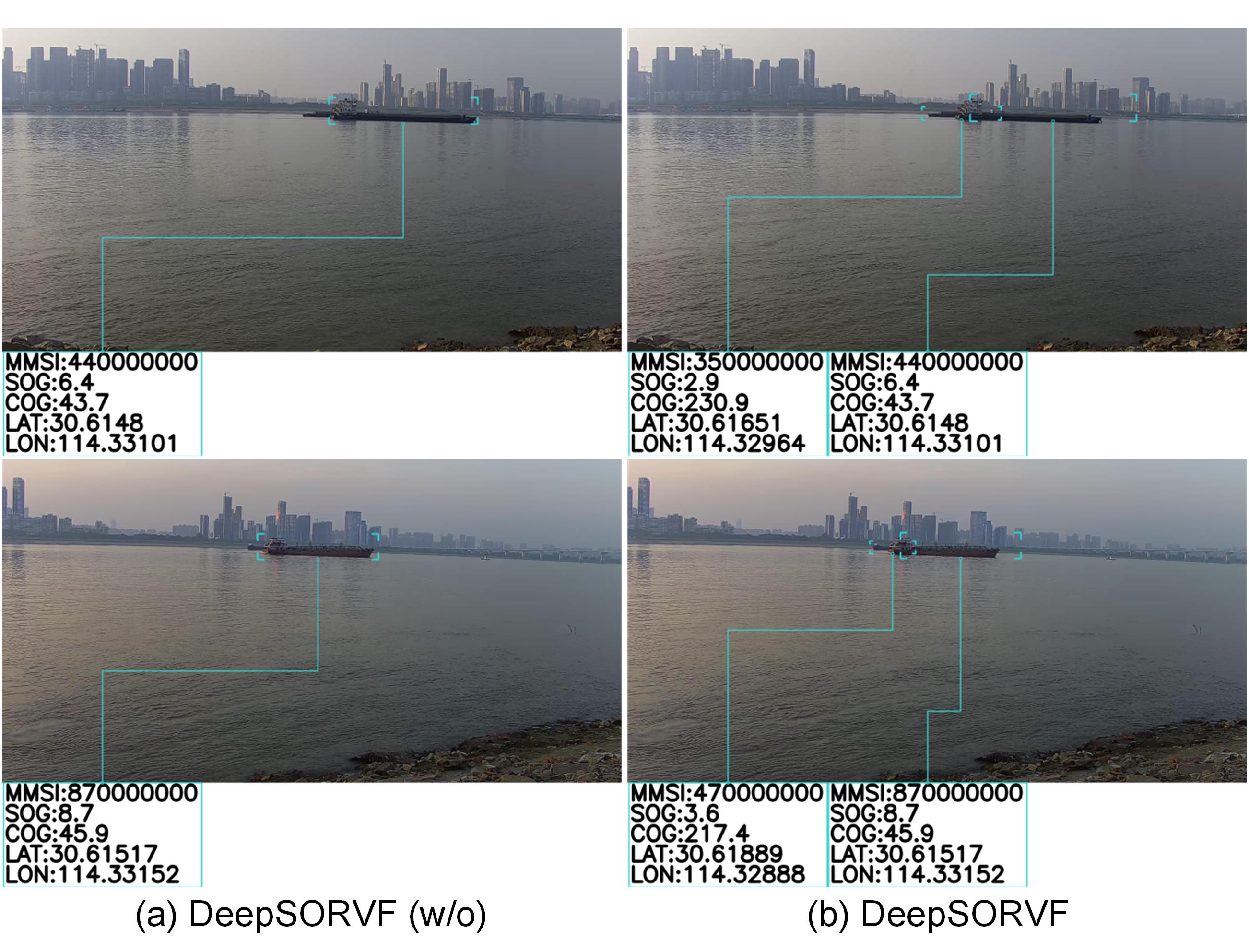
To provide a more understandable explanation, we display two examples of data fusion obtained by MSDF, MMDST, DeepSORVF (w/o), and DeepSORVF shown in Figs. 5 and 6. Specifically, Fig. 5 displays the visualized data fusion result captured by the bridge region camera. Since the MSDF only considers the vessel characteristic at the current moment, the vessel information is more likely to be matched incorrectly. In the 80-th second, the MSDF, MMDST, and DeepSORVF (w/o) are unable to match the vessel identification information since the detector fails to identify the partially occluded target. For the data collected by the riverside, the visual vessels are often more severely occluded, resulting in the complete disappearance of target features. By analyzing Fig. 6, the MSDF, MMDST, and DeepSORVF (w/o) will produce more missing detection and false matching. It is worth mentioning that the vessel occlusion will also affect the trajectory feature extraction and cause the feature matching failure. In contrast, the proposed DeepSORVF with the anti-occlusion strategy has a more stable data fusion effect and is suitable for a variety of scenarios.
IV-B3 Fusion Results on FVessel Dataset
Our DeepSORVF is also used to process more data in the FVessel dataset and calculate the , , , and . Table IV and Fig. 7 display the metric calculation results and the visualized fusion results, respectively. It can be found that the proposed method has stable fusion performance. The fusion accuracy (MOFA) of our method is between 73.19% and 98.68% and the average is 91.13%. In the evaluation of the other three metrics, our method also has a good performance. Through the comparison in Fig. 7, the results generated by our DeepSORVF are accurate and stable. The superiority of the proposed method benefits from the accurate prediction of the vessel bounding box by the anti-occlusion tracking method under the occlusion condition and the accurate matching based on the trajectory series.
| Detector | Data Fusion | Precision | Recall |
|---|---|---|---|
| Faster-RCNN [23] | ✗ | 89.04 | 90.74 |
| ✔ | 90.03 | 96.48 | |
| SSD [24] | ✗ | 94.98 | 88.14 |
| ✔ | 95.02 | 95.62 | |
| YOLOv4 [42] | ✗ | 96.43 | 76.97 |
| ✔ | 96.74 | 84.85 | |
| YOLOv5 [43] | ✗ | 98.78 | 83.70 |
| ✔ | 99.47 | 91.29 | |
| YOLOX [28] | ✗ | 98.91 | 94.13 |
| ✔ | 99.20 | 99.40 |
IV-C Influence of Data Fusion on Vessel Detection and Tracking
In our proposed method, the result of trajectory matching is fed as prior knowledge to the vessel detection and tracking tasks at the next moment for promoting the video-based vessel trajectory extraction. To verify that our proposed data fusion method can improve vessel detection and tracking performance, we conduct massive experiments on ten clips. In particular, we select five different deep neural networks as detectors, i.e., Faster-RCNN [23], SSD [24], YOLOv4 [42], YOLOv5 [43], and YOLOX [28]. Each detector has two versions, i.e., “Detection” and “Detection + Data Fusion”. Furthermore, all methods only process data once per second.
IV-C1 Evaluation Metric
To evaluate the performance of vessel detection, we select the and as evaluation metrics. Let , , and denote the number of the true positive, false positive, and false negative, the and can be given by
| (19) |
| (20) |
For vessel tracking, we tend to use MOTA as an evaluation metric, which can be defined as
| (21) |
where , , , and represent the numbers of the false positive, false negative, switch, and ground truth, respectively. Furthermore, we also adopt the , , and metrics. Theoretically, better detection results have higher and , and better tracking results have higher , , , and .
IV-C2 Vessel Detection and Tracking on Ten Clips
Table V compares the detection and of various detectors on ten clips. Due to the mutual occlusion between the targets, some vessel characteristics are easily hidden by another vessel. Therefore, detectors often suffer from missing detection, resulting in higher and poorer . In most cases, detectors are prone to produce false detection boxes in vessel encounter regions due to the overlapping of multiple vessel features. These false detection boxes will produce higher and poorer . In contrast, the proposed anti-occlusion method based on data fusion results can improve the performance of various detectors.
| Detector | Data Fusion | MOTA | IDP | IDR | IDF |
|---|---|---|---|---|---|
| Faster-RCNN [23] | ✗ | 75.19 | 68.03 | 69.00 | 68.43 |
| ✔ | 84.43 | 81.81 | 87.95 | 84.58 | |
| SSD [24] | ✗ | 81.36 | 84.49 | 78.77 | 81.14 |
| ✔ | 89.69 | 90.03 | 91.03 | 90.13 | |
| YOLOv4 [42] | ✗ | 70.92 | 71.61 | 56.66 | 63.08 |
| ✔ | 80.50 | 80.44 | 70.18 | 74.77 | |
| YOLOv5 [43] | ✗ | 81.72 | 88.68 | 75.08 | 81.12 |
| ✔ | 90.40 | 94.48 | 86.50 | 90.05 | |
| YOLOX [28] | ✗ | 92.61 | 89.80 | 85.36 | 87.50 |
| ✔ | 98.61 | 97.72 | 97.92 | 97.82 |
To compare the tracking performance, Table VI further shows the , , , and results of various detectors on ten clips. In contrast, the proposed data fusion method can significantly improve the tracking performance of all five detectors and reduce the number of missing and false detection. The performance improvement benefits from the proposed anti-occlusion method based on data fusion results. The proposed method can achieve more stable vessel tracking during the occlusion.
IV-D Running Time Analysis
| Video | Video Length | Processing Time |
|---|---|---|
| clip-01 | 01m51s | 0.27210.0230 |
| clip-02 | 01m36s | 0.25260.0323 |
| clip-03 | 03m42s | 0.29980.0413 |
| clip-04 | 02m42s | 0.24620.0289 |
| clip-05 | 03m05s | 0.24440.0321 |
| clip-06 | 02m38s | 0.26420.0344 |
| clip-07 | 11m10s | 0.22790.0391 |
| clip-08 | 05m07s | 0.24040.0364 |
| clip-09 | 08m39s | 0.25690.0256 |
| clip-10 | 02m46s | 0.25790.0304 |
| Average | – | 0.2562 |
The time complexity of the proposed method is a critical metric, which directly determines whether it can be used in actual engineering. In this work, we only process the data once per second to ensure practicability. Therefore, we are unable to use the frame per second (FPS) as an evaluation metric. Meanwhile, since the proposed method considers trajectory features, the time complexity is also related to the number and length of AIS- and video-based vessel trajectories. Consequently, it is also inaccurate to calculate the running time of a single image. Finally, we compute the processing time of one-second data for ten clips in Table II. The processing time of our method for each clip is shown in Fig. 8 and Table VII. It can be seen that our DeepSORVF has low time complexity and high practicability. It can process one second of data in 0.175-0.500 seconds and 0.2562 seconds on average.
IV-E Discussion
Although our proposed method adopts the prior knowledge-driven anti-occlusion tracking method and trajectory matching method to effectively improve the accuracy of data fusion, our method still has some limitations. In this section, we use the multiple object fusion accuracy (MOFA) and multiple object fusion precision (MOFP) as evaluation metrics, where the MOFP is a variant of the Multiple Object Tracking Precision (MOTP) [40] in the data fusion task. The MOFP can be given by
| (22) |
where denotes the distance of the -th MMSI matching pair in the -th second, is the number of matches in the -th second. Theoretically, a better fusion effect has higher MOFA and lower MOFP.
| Video | Methods | MOFA | MOFP |
|---|---|---|---|
| clip-02 | DeepSORVF (w/o) | 87.77 | 0.110 |
| DeepSORVF | 99.47 | 0.140 | |
| clip-03 | DeepSORVF (w/o) | 90.53 | 0.241 |
| DeepSORVF | 94.67 | 0.252 | |
| Average | DeepSORVF (w/o) | 88.92 | 0.175 |
| DeepSORVF | 97.02 | 0.196 |
Using clip-02 and clip-03 as examples, we compute their MOFA and MOFP. As shown in Table VIII, it can be found that the proposed anti-occlusion tracking method can significantly improve the accuracy of data fusion by comparing the MOFA. However, the DeepSORVF is slightly inferior to the DeepSORVF (w/o) without the anti-occlusion strategy in the bounding box localization precision evaluated by the MOFP. The more intuitive comparisons before and after the use of the anti-occlusion strategy are illustrated in Fig. 9. Our DeepSORVF with the anti-occlusion strategy can predict the vessel position and accurately match the occluded vessel information. However, the predicted bounding boxes still have some degree of bias in complex occlusion conditions. This deviation is mostly attributable to the inaccurate estimation of AIS and visual motion characteristics. When a vessel travels away from the camera, for instance, its visual movement speed generally slows and the object gets smaller. To further improve the vessel anti-occlusion performance, our future work will take into account the changing features of the moving vessels in the visual data.
V Conclusion
In this paper, we proposed a deep learning-based simple online and real-time vessel data fusion method (named DeepSORVF). The DeepSORVF could pair the vessel features of AIS with visual targets. Due to the fact that reciprocal occlusion between vessel targets may readily interfere with video-based trajectory extraction, we suggested a prior knowledge-driven anti-occlusion tracking method. Meanwhile, a novel asynchronous trajectory matching method was designed for robust data fusion. Comprehensive experiments on vessel detection, vessel tracking, data fusion, and running time analysis have demonstrated the superior performance of our DeepSORVF on the newly-developed FVessel dataset.
References
- [1] D. D. Bloisi, F. Previtali, A. Pennisi, D. Nardi, and M. Fiorini, “Enhancing automatic maritime surveillance systems with visual information,” IEEE Trans. Intell. Transp. Syst., vol. 18, no. 4, pp. 824–833, Aug. 2016.
- [2] X. Zhang, X. Fu, Z. Xiao, H. Xu, and Z. Qin, “Vessel trajectory prediction in maritime transportation: current approaches and beyond,” IEEE Trans. Intell. Transp. Syst., [online], doi: 10.1109/TITS.2022.3192574.
- [3] D. Y. Kim, B. Ristic, R. Guan, and L. Rosenberg, “A bernoulli track-before-detect filter for interacting targets in maritime radar,” IEEE Trans. Aerosp. Electron. Syst., vol. 57, no. 3, pp. 1981–1991, Jun. 2021.
- [4] J. Feng, B. Li, L. Tian, and C. Dong, “Rapid ship detection method on movable platform based on discriminative multi-size gradient features and multi-branch support vector machine,” IEEE Trans. Intell. Transp. Syst., vol. 23, no. 2, pp. 1357–1367, Feb. 2022.
- [5] J. Chen, Q. Hu, R. Zhao, P. Guojun, and C. Yang, “Tracking a vessel by combining video and ais reports,” in Proc. FGCN, 2008, pp. 374–378.
- [6] W. Man and L. Zhiyong, “The information fusion based on ais and video data,” in Proc. IEEE ICCSNT, 2016, pp. 336–339.
- [7] Y. Lu, H. Ma, E. Smart, B. Vuksanovic, J. Chiverton, S. R. Prabhu, M. Glaister, E. Dunston, and C. Hancock, “Fusion of camera-based vessel detection and ais for maritime surveillance,” in Proc. IEEE ICAC, 2021, pp. 1–6.
- [8] Z. Huang, Q. Hu, Q. Mei, C. Yang, and Z. Wu, “Identity recognition on waterways: a novel ship information tracking method based on multimodal data,” J. Navig., vol. 74, no. 6, pp. 1336–1352, May 2021.
- [9] R. W. Liu, Y. Guo, J. Nie, Q. Hu, Z. Xiong, H. Yu, and M. Guizani, “Intelligent edge-enabled efficient multi-source data fusion for autonomous surface vehicles in maritime internet of things,” IEEE Trans. Green Commun. Networking, vol. 6, no. 3, pp. 1574–1587, Mar. 2022.
- [10] K. El-Darymli, P. McGuire, D. Power, and C. R. Moloney, “Target detection in synthetic aperture radar imagery: A state-of-the-art survey,” J. Appl. Remote Sens., vol. 7, no. 1, p. 071598, Mar. 2013.
- [11] W. Zhou and P. Chen, “A deep attention mechanism method for maritime salient ship detection in complex sea background,” Opt. Lett., vol. 17, no. 7, pp. 438–443, Jul. 2021.
- [12] R. W. Liu, W. Yuan, X. Chen, and Y. Lu, “An enhanced cnn-enabled learning method for promoting ship detection in maritime surveillance system,” Ocean Eng., vol. 235, p. 109435, Sep. 2021.
- [13] X. Chen, X. Xu, Y. Yang, Y. Huang, J. Chen, and Y. Yan, “Visual ship tracking via a hybrid kernelized correlation filter and anomaly cleansing framework,” Appl. Ocean Res., vol. 106, p. 102455, Jan. 2021.
- [14] D.-w. Gao, Y.-s. Zhu, J.-f. Zhang, Y.-k. He, K. Yan, and B.-r. Yan, “A novel mp-lstm method for ship trajectory prediction based on ais data,” Ocean Eng., vol. 228, p. 108956, May 2021.
- [15] Z. Xiao, X. Fu, L. Zhang, and R. S. M. Goh, “Traffic pattern mining and forecasting technologies in maritime traffic service networks: A comprehensive survey,” IEEE Trans. Intell. Transp. Syst., vol. 21, no. 5, pp. 1796–1825, May 2019.
- [16] D. K. Prasad, C. K. Prasath, D. Rajan, L. Rachmawati, E. Rajabally, and C. Quek, “Object detection in a maritime environment: Performance evaluation of background subtraction methods,” IEEE Trans. Intell. Transp. Syst., vol. 20, no. 5, pp. 1787–1802, May 2018.
- [17] W.-C. Hu, C.-Y. Yang, and D.-Y. Huang, “Robust real-time ship detection and tracking for visual surveillance of cage aquaculture,” J. Visual Commun. Image Represent., vol. 22, no. 6, pp. 543–556, Aug. 2011.
- [18] D. D. Bloisi, A. Pennisi, and L. Iocchi, “Background modeling in the maritime domain,” Mach. Vis. Appl., vol. 25, no. 5, pp. 1257–1269, Dec. 2014.
- [19] C. Zhu, H. Zhou, R. Wang, and J. Guo, “A novel hierarchical method of ship detection from spaceborne optical image based on shape and texture features,” IEEE Trans. Geosci. Remote Sens., vol. 48, no. 9, pp. 3446–3456, Apr. 2010.
- [20] Y. Zhang, Q.-Z. Li, and F.-N. Zang, “Ship detection for visual maritime surveillance from non-stationary platforms,” Ocean Eng., vol. 141, pp. 53–63, Sep. 2017.
- [21] X. Chen, S. Wang, C. Shi, H. Wu, J. Zhao, and J. Fu, “Robust ship tracking via multi-view learning and sparse representation,” J. Navig., vol. 72, no. 1, pp. 176–192, Sep. 2019.
- [22] R. Girshick, J. Donahue, T. Darrell, and J. Malik, “Region-based convolutional networks for accurate object detection and segmentation,” IEEE Trans. Pattern Anal. Mach. Intell., vol. 38, no. 1, pp. 142–158, May 2015.
- [23] S. Ren, K. He, R. Girshick, and J. Sun, “Faster r-cnn: Towards real-time object detection with region proposal networks.” IEEE Trans. Pattern Anal. Mach. Intell., vol. 39, no. 6, pp. 1137–1149, Jun. 2016.
- [24] W. Liu, D. Anguelov, D. Erhan, C. Szegedy, S. Reed, C.-Y. Fu, and A. C. Berg, “SSD: Single shot multibox detector,” in Proc. ECCV, 2016, pp. 21–37.
- [25] Z. Li and F. Zhou, “FSSD: feature fusion single shot multibox detector,” arXiv preprint arXiv:1712.00960, 2017.
- [26] J. Redmon, S. Divvala, R. Girshick, and A. Farhadi, “You only look once: Unified, real-time object detection,” in Proc. IEEE CVPR, 2016, pp. 779–788.
- [27] J. Redmon and A. Farhadi, “Yolo9000: better, faster, stronger,” in Proc. IEEE CVPR, 2017, pp. 7263–7271.
- [28] Z. Ge, S. Liu, F. Wang, Z. Li, and J. Sun, “Yolox: Exceeding yolo series in 2021,” arXiv preprint arXiv:2107.08430, 2021.
- [29] J. Redmon and A. Farhadi, “Yolov3: An incremental improvement,” arXiv preprint arXiv:1804.02767, 2018.
- [30] Z. Shao, L. Wang, Z. Wang, W. Du, and W. Wu, “Saliency-aware convolution neural network for ship detection in surveillance video,” IEEE Trans. Circuits Syst. Video Technol., vol. 30, no. 3, pp. 781–794, Feb. 2019.
- [31] Z. Chen, D. Chen, Y. Zhang, X. Cheng, M. Zhang, and C. Wu, “Deep learning for autonomous ship-oriented small ship detection,” Saf. Sci., vol. 130, p. 104812, Oct. 2020.
- [32] X. Yang, Y. Wang, N. Wang, and X. Gao, “An enhanced SiamMask network for coastal ship tracking,” IEEE Trans. Geosci. Remote Sens., vol. 60, pp. 1–11, Oct. 2021.
- [33] N. Wojke, A. Bewley, and D. Paulus, “Simple online and realtime tracking with a deep association metric,” in Proc. IEEE ICIP, 2017, pp. 3645–3649.
- [34] F. A. Palmieri, F. Castaldo, and G. Marino, “Harbour surveillance with cameras calibrated with ais data,” in Proc. IEEE Aerospace Conference, 2013, pp. 1–8.
- [35] D. K. Prasad, C. K. Prasath, D. Rajan, L. Rachmawati, E. Rajabally, and C. Quek, “Object detection in a maritime environment: Performance evaluation of background subtraction methods,” IEEE Trans. Intell. Transp. Syst., vol. 20, no. 5, pp. 1787–1802, May 2019.
- [36] B. Bovcon, J. Muhovič, D. Vranac, D. Mozetič, J. Perš, and M. Kristan, “Mods–a usv-oriented object detection and obstacle segmentation benchmark,” IEEE Trans. Intell. Transp. Syst., vol. 23, no. 8, pp. 13 403–13 418, Aug. 2022.
- [37] S. Zagoruyko and N. Komodakis, “Wide residual networks,” arXiv preprint arXiv:1605.07146, 2016.
- [38] M. Müller, “Dynamic time warping,” Inform. Retrieval for Music and Motion, pp. 69–84, Jan. 2007.
- [39] S. Salvador and P. Chan, “Toward accurate dynamic time warping in linear time and space,” Intell. Data Anal., vol. 11, no. 5, pp. 561–580, Oct. 2007.
- [40] K. Bernardin and R. Stiefelhagen, “Evaluating multiple object tracking performance: the clear mot metrics,” EURASIP J. Image Video Process., vol. 2008, pp. 1–10, Apr. 2008.
- [41] E. Ristani, F. Solera, R. Zou, R. Cucchiara, and C. Tomasi, “Performance measures and a data set for multi-target, multi-camera tracking,” in Proc. ECCV, 2016, pp. 17–35.
- [42] A. Bochkovskiy, C.-Y. Wang, and H.-Y. M. Liao, “Yolov4: Optimal speed and accuracy of object detection,” arXiv preprint arXiv:2004.10934, 2020.
- [43] G. Jocher, A. Stoken, J. Borovec, A. Chaurasia, L. Changyu, A. Laughing, A. Hogan, J. Hajek, L. Diaconu, Y. Marc et al., “ultralytics/yolov5: v5. 0-yolov5-p6 1280 models aws supervise. ly and youtube integrations,” Zenodo, vol. 11, 2021.