Local setting of spin textures in a granular antiferromagnet
Abstract
Controlling the magnetic order of antiferromagnets is challenging due to their vanishing net magnetization. For this reason, the study of local spin textures in antiferromagnets is restricted by the difficulty in nucleating such states. Here, using atomistic simulations we demonstrate a method for nucleating localized spin textures in the grains of thin film antiferromagnet, -IrMn3. Utilising the exchange bias coupling between a ferromagnet and an antiferromagnet, we set the spin texture in the latter from a predefined spin texture in the former by means of a thermal cycling procedure. The local textures set in the antiferromagnetic grains are shown to be stable against field perturbations. We also discuss how various material parameters affect the efficiency of the setting and the characteristics of these set textures. The setting of antiferromagnetic spin textures provides a potential route to antiferromagnetic spintronic devices with non-collinear spin states such as skyrmions, bubbles and domain walls.
I Introduction
The interest in antiferromagnetic (AFM) states is founded on their robustness against perturbations, such as magnetic fields, as well as on their physical properties that extend the potential of spintronics beyond that based on ferromagnets (FM) only Jungwirth et al. (2016); Baltz et al. (2018). Analogously to FMs, local spin textures with inhomogeneous magnetization configurations exist in AFMs under conditions yielding a favorable energy balance. Due to the different local symmetries, the expected properties of these AFM spin textures differ from and have interesting advantages over their ferromagnetic counterparts Gomonay et al. (2018). However, due to the lack of net magnetization, the main barrier to accessing these properties is the difficulty in experimentally nucleating them. Typically, structures with a size comparable to the critical single domain size or domain wall width are patterned to make the global multidomain structure of continuous films energetically unfavorable so that local spin textures form instead Salazar-Alvarez et al. (2009); Wu et al. (2011). Alternative methods for the nucleation of local AFM spin textures have also been proposed: through injection of vertical spin-polarized current in nanostructured devices Zhang et al. (2016) or through subjecting the system to ultrafast laser pulses Khoshlahni et al. (2019).
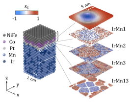
Here, we use atomistic simulations to demonstrate a local nucleation of spin textures in AFM grains that does not require complex device geometries and is applicable beyond metallic AFMs. Utilizing the exchange bias coupling at a FM/AFM interface and a thermal cycling procedure, we set the spin texture in the AFM grains during their magnetic ordering from predefined spin textures in the FM. This method follows previous experimental works on setting AFM domains and domain walls Vallejo-Fernandez et al. (2010), vortices Salazar-Alvarez et al. (2009); Wu et al. (2011), and bubbles Rana et al. (2021). In this work, we nucleate prototypical spin textures, namely skyrmion bubbles (Sk), in a continuous thin film FM using a carefully optimized magnetic stack and an external field. We then use this as a template for the setting of the underlying AFM grains, as shown in Figure 1. Note, however, that the spin textures set in the AFM grains are not topologically protected despite the initial template comprising of Sk bubbles.
II The simulation system
The simulation system, Ni80Fe20 (0.87)/Co (0.33)/Pt (0.47)/-IrMn3 (5 nm), is based on an experimental one that has been optimized for the nucleation of Sks in the FM layer Rana et al. (2021); Boulle et al. (2016). The ultrathin Co/Pt bilayer provides a strong interfacial Dzyaloshinskii-Moriya interaction (DMI) Yang et al. (2015) and some perpendicular magnetic surface anisotropy, while the thickness of the NiFe layer allows the vanishing of the total anisotropy. The magnetic coupling between the FM and AFM layers is preserved due to finite atomic intermixing. For the AFM layer we use the non-collinear -IrMn3, due to its large exchange bias coupling originating from the statistical imbalance of spins in the four magnetic sublattices, which yields uncompensated interfacial spins Jenkins et al. (2020). Moreover, the four easy axes Jenkins et al. (2019)
of IrMn3 may facilitate the magnetic moment winding that is necessary for a non-collinear spin texture formation. The magnetic properties of -IrMn3 relating to its non-trivial spin structure have been thoroughly characterized using the atomistic simulation software package vampire Jenkins et al. (2021a); Evans et al. (2014), which is also used for this work. The simulations utilized the ARCHER2 supercomputer with typical simulations running on 1024 CPU cores due to the large number of Monte Carlo time steps and large system size of around spins.
The spin Hamiltonian governing the energetics of the system is given by
| (1) |
The first term is the exchange interaction, where subscripts i and j refer to spins on sites and , is the exchange constant and is the spin vector. The second term describes the Néel pair anisotropy that rotates the spins radially/tangentially with respect to a nearest neighbor of a given element and is used to simulate the interfacial perpendicular magnetic anisotropy (Co spins point radially to Pt sites) and correct anisotropy of IrMn3 (Mn spins point tangentially to Ir sites) Jenkins et al. (2019). Here, is the Néel pair anisotropy constant, is a unit vector between atoms and , and is the number of nearest neighbors. The third term that stabilizes the topological states is the DMI interaction where is the DMI vector, defined as , where is the DMI strength and is the unit vector between the magnetic atoms at site and and Pt at site .
The fourth term is the Zeeman energy where is the atomic magnetic moment and is the external induction or flux density. For the sake of computational simplicity, we have not included the RKKY-interaction, which would increase the exchange interaction strength between the FM and AFM layers but not change the physics of the local setting presented in this work.
The temperature-dependence of the magnetic state is simulated using an adaptive Monte Carlo Metropolis algorithm Alzate-Cardona et al. (2019), which is ideal for naturally simulating the temperature-evolution of the magnetic state. The field-dependence, on the other hand, was simulated using the stochastic Landau-Lifshitz-Gilbert equation and a Heun numerical scheme García-Palacios and Lázaro (1998). We have set the damping parameter to 1 to promote rapid relaxation and therefore faster numerical calculation, since our goal is to reach the ground state rather than follow the exact dynamics. The timestep is 0.1 fs.
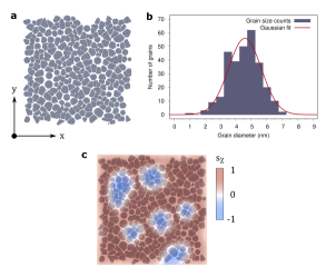
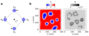
The simulation system with a size of 100x100x6.67 nm3 has a layer-dependent structure: the FM/Pt multilayer is a single crystal while the AFM layer is granular with an average grain size and spacing of 5 and 0.75 nm, respectively, in line with experimental data Vallejo-Fernandez et al. (2008). Similarly to an experimental system, the AFM grains are not coupled to each other O’Grady et al. (2010). On the other hand, the FM grains are coupled and as the FM and AFM grains are coincident, the FM layer can be modeled as a single crystal. The grain structure (illustrated in Figure 2) is created using a Voronoi construction as described previously in Ref. Jenkins et al. (2021b). It should be noted that we have not implemented periodic boundary conditions as they are incompatible with the implementation of the AFM grain structure. The crystal orientation of the entire simulation stack is such that the [001] crystal axis is along the film normal.
The onsite magnetic properties of each magnetic element in the simulation stack are listed in Table 1. For the permalloy layer (Ni80Fe20), was calculated from the saturation magnetization of A/m using Evans et al. (2014), where is the lattice constant and is the
| Parameter | Ni80Fe20 | Co | Mn |
|---|---|---|---|
| () | 1.05 | 1.72 | 2.6 |
| (10-22 J/atom) | 0.025 (Pt) | -4.22 (Ir) | |
| Intermixing (Å) | 1.67 | 1.67 | 3.34 |
| NiFe | Co | Pt | Mn | |||
|---|---|---|---|---|---|---|
| NiFe | 3.8 Evans et al. (2014) | 5 | 0.5* | 1.21 Szunyogh et al. (2009) | ||
| Co | 5 | 6.1 Evans et al. (2014) | 0.5* | 1.21 Szunyogh et al. (2009) | ||
| Pt | 0.5* | 0.5* | ||||
| Mn | 1.21 Szunyogh et al. (2009) | 1.21 Szunyogh et al. (2009) |
|
number of atoms in the unit cell. For Co the values were obtained from Ref. Evans et al. (2014) and for -IrMn3 from Ref. Jenkins et al. (2020). The intermixing in Tables 1 refers to the thickness over which the given layer is intermixed with the one below. The intersite exchange () and DMI () interactions are listed in Table 2. For Ni80Fe20 the is calculated from the expected Curie temperature of K using , where is the spin-wave mean-field correction and is the number of nearest neighbors Evans et al. (2014). For Co the values are obtained from Ref. Evans et al. (2014) and for -IrMn3 from ab initio calculations Szunyogh et al. (2009). For the coupling strength between Co and NiFe, we have used the average Co-Co and NiFe-NiFe coupling strengths. The DMI value used in our calculations is J/link, which corresponds to an interfacial DMI parameter = 0.5 pJ/m for the limiting case of a flat interface. Experimental values available in the literature for similar stacks (measured by Brillouin light scattering) range from 0.15 to 1.25 pJ/m Ma et al. (2017); Khan et al. (2018); Rana et al. (2021). We have verified that varying the DMI value within this range does not alter the main conclusions of the paper.
III Local setting of the AFM grains
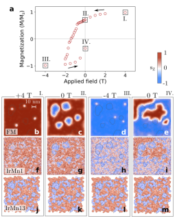
The localized setting of the AFM grains is realized by means of thermal cycling. More precisely, the simulations were carried out in three steps: i) FM Sk nucleation, ii) field-cooling, and iii) field removal. During the first step (Figure 3b-d), the system was equilibrated at 600 K in an applied field of Bz = 0.5 T parallel to the film normal for Monte-Carlo steps. Because 600 K is above the Néel temperature (TN) of the AFM layer ( 510 K, see Figure 3a) and below the Curie temperature of the FM layer ( K, see Figure 3a), this phase allows the nucleation of nanoscale Sks in the FM layer while the AFM layer remains disordered throughout. This ensures that the setting of spin textures is from the FM to the AFM layer and not vice versa.
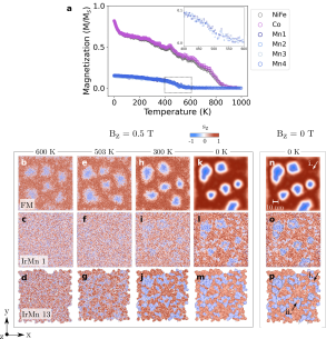
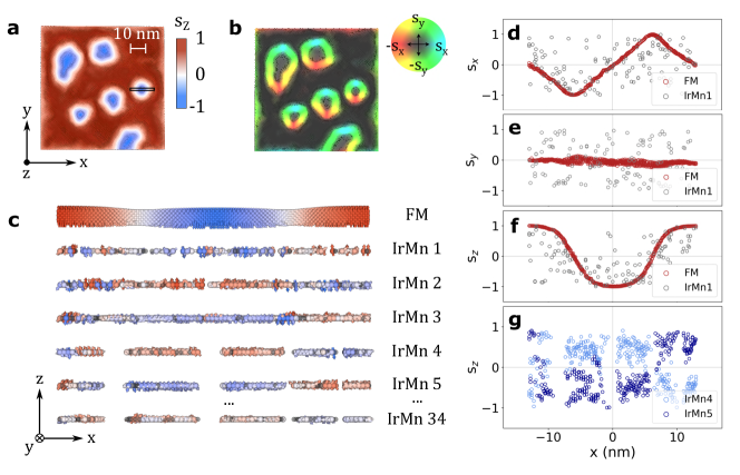
In the second simulation step (Figure 3e-g), the system is cooled down to 0 K in the same field in order to further stabilize the FM layer and to set the AFM layer upon crossing the Néel temperature . The bulk AFM (exemplified by IrMn layer 13 in Figure 3) begins to set at the blocking temperature of the IrMn grains around K. The interfacial moments of the AFM (IrMn 1 in Figure 3), on the other hand, are subject to more thermal noise and the setting of the AFM spin textures is more difficult to discern. This is likely due to the reversible component fluctuating with the FM spins. At K (Figure 3k-m), the setting of the the AFM interface and bulk based on the FM spin textures becomes clear: the textures observed in the FM are largely reproduced in the bulk AFM as highlighted by the contours in Figure 3o,p and their exact shape is governed by the grain boundaries of the AFM.
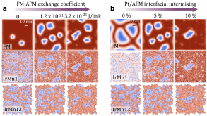
Superimposed to the set spin textures there are also random spin textures in the AFM bulk that don’t correspond to the FM spin configuration. These discrepancies can be divided into two categories based on their location and the extent of deviation: discrepancies exemplified by i. in Figure 3n,p are in the region of uniformly magnetized FM and often accompanied by slight impressions in the adjacent FM layer. Discrepancies exemplified by ii. in Figure 3p are inside the imprinted spin textures and deviate completely from the FM spin configuration. The reason for these discrepancies is likely due to the FM-AFM exchange interaction not being strong enough to set all the grains, which is demonstrated in Figure 4a - stronger exchange interaction improves the FM-AFM spin texture conformity while zero exchange interaction results in the AFM having a completely random domain structure. A similar outcome is realized when the intermixing at the Pt/AFM interface is increased, as shown in Figure 4b because more FM and AFM spins will come to a direct contact, which facilitates the AFM-FM exchange interaction. We recall that for the sake of computational simplicity we have not included the RKKY-interaction. This would increase the exchange interaction strength between the FM and AFM layers and give rise to non-zero exchange bias in the absence of intermixing but not change the physics of the local setting presented in this work. It is also possible that some of the i. type discrepancies are residual imprintings of FM Sks that moved or were annihilated during the field-cooling (compare the FM Sk locations in Figures 3b and 3n). We also point out that layer intermixing is likely to finely modify some magnetic properties Baltz (2013) and parameters like DMI, which can also alter the imprinting efficiency.
Finally, the last simulation step shown in Figure 3n-p is the removal of the external field, which causes only minor changes to the spin textures throughout the stack, demonstrating the zero-field stability of the set localized AFM spin textures.
In summary, this set of simulations shows that i) spin textures (here Sks) initially nucleated in a FM layer serve as a template for the localized setting of spin textures in the AFM grains during a thermal cycling protocol, ii) the setting of the AFM textures penetrates into the bulk of the AFM and iii) the AFM textures are stable at remanence. Note that these conclusions are valid for any final temperature below , including room temperature in our case (see Figure 3h-j). The robustness and universality of our results is later further demonstrated in Figure 8b where we show the setting of the AFM grains based on another FM spin texture, namely maze domains.
IV Microscopic details of the local setting
The exact nature and morphology of the set textures (Figure 5) is discussed next. The radii of the Sks in the FM (Figure 5a-b) range from 10 to 20 nm and their shape is rather irregular, most likely due to the pinning by the grain boundaries of the AFM layer (see Figure 2c for the conformity between the Sk shapes and the AFM grain structure). The variation of the spin components , , and across the cross-section shows behavior characteristic of a Néel type Sk (Figure 5d-f), which is in good agreement with the interfacial DMI, and its strength being above the critical strength for a Bloch to Néel domain wall transition (). The and components can be fitted using and functions, respectively, where is the domain wall center location and is the domain wall width. For the selected Skyrmion, nm, which is in the same order of magnitude as expected by theory Wang et al. (2018).
We calculate the winding number for our discretized system by summing up the topological charge density per a square cell illustrated in Figure 6a:
| (2) |
| (3) |
where is the signed area of a triangle delimited by , , and , being the magnetization vector at site Berg and Lüscher (1981); Böttcher et al. (2018). Figure 6 shows the calculation of the winding number for the FM layer in Figure 3n, which yields for each Sk bubble, confirming their topological nature. It should be noted that the FM spin texture at the boundary of the simulation system, is not a Sk bubble (non-integer Q 0.4) and thus not topologically protected. Considering that the sum of the topological charge over the whole lattice should return an integer, the winding number of 0.4 of the FM texture should be compensated elsewhere. As the topological charge is only being calculated for the FM layer, it is possible that the AFM spins compensate the fractional Q or, alternatively, the existence of the boundary and pinning from the AFM may cause the fractional Q as technically Q is only defined for infinite systems.
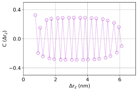
At the AFM interface (IrMn 1 in Figure 5), the , , and components show average behavior that corresponds to that of the FM layer, providing further support for the AFM spin texture setting from the FM template. The increased noise is likely due to the strong anisotropy of -IrMn3, interfacial intermixing, and the interfacial magnetization comprising of a reversible and irreversible component Nogués and Schuller (1999); Jenkins et al. (2020) where the former follows the FM spins while the latter is strongly coupled to the AFM bulk. The different behaviors of these two components are also observed during the field cycling as will be discussed later. In the AFM layer, the spin texture setting propagates from the topmost layer down to the bottom layer with the polarity of the texture alternating between each consecutive monolayer, as was shown in Figure 1. This is in a good agreement with the typical tetrahedral 3Q spin state of the AFM ordering of -IrMn3 Sakuma et al. (2003) and [001] crystal ordering. To further confirm the alternating magnetization in the antiferromagnet we calculate the partial spin-spin correlation function between one layer of the ferromagnet and each layer of the antiferromagnet, shown in Figure 7. The spin-spin correlation function is given by
| (4) |
where are atoms in the center ferromagnetic layer (containing the ferromagnetic spin texture), are atoms in the antiferromagnet separated by a position vector with components only (we do not consider pairs of atoms separated laterally) and is the total number of pairs considered. This gives the correlation between the ferromagnet and successive layers of the antiferromagnet, with a value of 1 being full correlation and -1 being fully anti-correlated. In the case of the spin texture the ordering of the interfacial moments of the AFM is highly correlated with the ferromagnetic order, leading to a net and alternating correlation between the FM and each layer of the AFM in the system. In the absence of FM-AFM coupling there is no net correlation and in the case of no spin texture the correlation is similar. The interfacial layer feels a strong exchange field from the ferromagnet leading to a large positive correlation, while the next two subsurface layer suffer frustration due to the intermixing with the ferromagnetic atoms. The bulk correlation is approximately constant but with a small decrease in the strength of correlation towards the bottom of the antiferromagnetic layer due to the loss of surface exchange bonds and a local decrease in antiferromagnetic surface order, in agreement with expectations Jenkins and Evans (2018); Jabakhanji and Ghader (2023); Ga et al. (2023).
In the bulk of the AFM (IrMn 13 in Figure 5) the noise is reduced, as there is no need to accommodate intermixing and the resulting non-IrMn AFM bonds, but some noise remains from the local nature of the anisotropy of -IrMn3 Jenkins et al. (2019). The behavior of the component follows that of the FM layer, with the only exception being that the domain walls are narrower as they follow the AFM grain boundaries. The penetration depth of the setting, down to the last layer IrMn 34
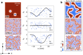
which is 5 nm away from the interface, is in good agreement with experimental reports of vortices in CoO and NiO Wu et al. (2011) and exchange springs in -IrMn3 Reichlová et al. (2016), which could propagate over the whole AFM thickness. As a control simulation, in Figure 8a we show that for a system without FM-AFM interfacial exchange coupling there is no correspondence between of the FM and AFM layers and instead the setting of the AFM grains is random.
V Field-stability of the set AF grains
Next, we study the effect of cycling the external field (oriented along the film normal) on the spin textures throughout the simulation stack. As expected, the hysteresis loop (Figure 9a) shows a shift of T towards negative fields due to the exchange bias from the uncompensated, irreversible interfacial Mn spins Jenkins et al. (2020). The spin texture evolution, on the other hand, strongly depends on the layer. The FM layer follows the field, nearly saturating at strong fields (Figure 9b,d) and gradually reversing at intermediate fields by the expansion of Sk bubbles. The AFM bulk, on the other hand, is unchanged throughout the field cycle as seen in Figure 9j-m. This can also be seen in the fact that at remanence, the FM layer (Figure 9c,e) adopts a configuration that conforms with that of the AFM layer. The AFM interface comprises a reversible component that follows the FM and an irreversible component that abides by the AFM bulk, and therefore shows a behavior that is a mixture of the two (Figure 9f-l). This shows that the local spin textures that have been set remain unaltered in the AFM bulk and partially at the interface even after the original Sks in the FM layer are annihilated. This means that we can transform a system with Sks in the FM layer and no spin textures in the AFM (Figure 3a-c) to a system with no Sk in the FM layer
but pre-defined spin textures in the AFM layer (Figure 9d-l) using consecutive thermal and field cycling processes. This opens up perspectives for further studies of spintronic properties of isolated, localized spin textures in an AFM.
VI Discussion
Here we open the discussion on future study of topologically protected states in the real space of compensated magnets as they hold promise of favorable and technologically relevant properties Jungwirth et al. (2016); Baltz et al. (2018); Šmejkal et al. (2018). These spin textures cannot be continuously transformed into a topologically trivial state and therefore are remarkably stable. Moreover, they impact the physical properties of the system as the winding of the spins allows the electrons to acquire a non-zero geometric phase Xiao et al. (2010); Göbel et al. (2018) when interacting with the local spin structure. While our work demonstrates the localized setting of non-topological spin textures in AFM grains, the technique we have presented could be applied and optimized for continuous films of AFMs or compensated magnets with spin-split band structure Chen et al. (2014); Šmejkal et al. (2022). The latter group is interesting due to their novel transport phenomena such as spontaneous anomalous Hall effect (AHE) Nakatsuji et al. (2015); Feng et al. (2022); Reichlová et al. (2021) and spin current generation Železný et al. (2017); González-Hernández et al. (2021); Bose et al. (2022) allowed by the novel band topologies. A particular topological state of interest would be Sks with compensated magnetic ordering - due to the anti-parallel interatomic exchange interactions they have not only zero net magnetization but also zero topological charge, which ensure robustness against external fields and vanishing skyrmion Zhang et al. (2016); Barker and Tretiakov (2016) and topological Hall effects Göbel et al. (2017). Other predicted effects of AFM Sks on the transport properties include the non-vanishing topological spin Hall effect Göbel et al. (2017); Akosa et al. (2018) and a longitudinal Sk velocity exceeding that of the FM Sks Zhang et al. (2016); Barker and Tretiakov (2016). These properties make Sks with compensated magnetic ordering not only fascinating subjects for studies on topology but also competitive information carrier candidates for ultra-dense, ultra-fast, low-power spintronic devices.
VII Conclusion
In conclusion, we have theoretically demonstrated the setting of localized spin textures in antiferromagnetic -IrMn3 by using predefined spin textures in an adjacent exchange-coupled ferromagnet as a template. This setting of non-topological spin textures was realized by a thermal cycling procedure and it was shown to extend beyond the interface through the entire thickness of the antiferromagnet (here 5 nm). The set AFM textures showed remarkable stability against field perturbations and the setting efficiency as well as the morphologies of the set AFM textures were shown to depend on various material parameters. This work offers a solution for overcoming the challenge of nucleating localized real-space spin textures in compensated magnets with zero net magnetization, promoting the extension of local spin texture studies beyond ferromagnets.
Data access statement
The raw data for this paper were generated at ARCHER2 . Derived data supporting the findings of this study are available from the corresponding authors on request.
Acknowledgements.
This study was partially supported by the France-UK Alliance Hubert Curien program (PHC) (Grant No. 46298XC) and the UK EPSRC program (Grant No. EP/V007211/1). This work used the ARCHER2 UK National Supercomputing Service (https://www.archer2.ac.uk).References
- Jungwirth et al. (2016) T. Jungwirth, X. Marti, P. Wadley, and J. Wunderlich, “Antiferromagnetic spintronics,” Nature Nanotechnology 11, 231–241 (2016).
- Baltz et al. (2018) V. Baltz, A. Manchon, M. Tsoi, T. Moriyama, T. Ono, and Y. Tserkovnyak, “Antiferromagnetic spintronics,” Reviews of Modern Physics 90, 015005 (2018).
- Gomonay et al. (2018) O. Gomonay, V. Baltz, A. Brataas, and Y. Tserkovnyak, “Antiferromagnetic spin textures and dynamics,” Nature Physics 14, 213–216 (2018).
- Salazar-Alvarez et al. (2009) G. Salazar-Alvarez, J. J. Kavich, J. Sort, A. Mugarza, S. Stepanow, A. Potenza, H. Marchetto, S. S. Dhesi, V. Baltz, B. Dieny, A. Weber, L. J. Heyderman, J. Nogués, and P. Gambardella, “Direct evidence of imprinted vortex states in the antiferromagnet of exchange biased microdisks,” Applied Physics Letters 95, 012510 (2009).
- Wu et al. (2011) J. Wu, D. Carlton, J. S. Park, Y. Meng, E. Arenholz, A. Doran, A. T. Young, A. Scholl, C. Hwang, H. W. Zhao, J. Bokor, and Z. Q. Qiu, “Direct observation of imprinted antiferromagnetic vortex states in CoO/Fe/Ag(001) discs,” Nature Physics 7, 303–306 (2011).
- Zhang et al. (2016) Xichao Zhang, Yan Zhou, and Motohiko Ezawa, “Antiferromagnetic skyrmion: Stability, creation and manipulation,” Scientific Reports 6 (2016).
- Khoshlahni et al. (2019) Rohollah Khoshlahni, Alireza Qaiumzadeh, Anders Bergman, and Arne Brataas, “Ultrafast generation and dynamics of isolated skyrmions in antiferromagnetic insulators,” Physical Review B 99, 054423 (2019).
- Vallejo-Fernandez et al. (2010) G. Vallejo-Fernandez, T. Deakin, K. O’Grady, S. Oh, Q. Leng, and M. Pakala, “Measurement of the antiferromagnet activity in exchange bias systems,” Journal of Applied Physics 107, 09D709 (2010).
- Rana et al. (2021) Kumari Gaurav Rana, Rafael Lopes Seeger, Sandra Ruiz-Gómez, Roméo Juge, Qiang Zhang, Kaushik Bairagi, Van Tuong Pham, Mohamed Belmeguenai, Stéphane Auffret, Michael Foerster, Lucia Aballe, Gilles Gaudin, Vincent Baltz, and Olivier Boulle, “Imprint from ferromagnetic skyrmions in an antiferromagnet via exchange bias,” Applied Physics Letters 119, 192407 (2021).
- Boulle et al. (2016) Olivier Boulle, Jan Vogel, Hongxin Yang, Stefania Pizzini, Dayane de Souza Chaves, Andrea Locatelli, Tevfik Onur Menteş, Alessandro Sala, Liliana D. Buda-Prejbeanu, Olivier Klein, Mohamed Belmeguenai, Yves Roussigné, Andrey Stashkevich, Salim Mourad Chérif, Lucia Aballe, Michael Foerster, Mairbek Chshiev, Stéphane Auffret, Ioan Mihai Miron, and Gilles Gaudin, “Room-temperature chiral magnetic skyrmions in ultrathin magnetic nanostructures,” Nature Nanotechnology 11, 449–454 (2016).
- Yang et al. (2015) Hongxin Yang, André Thiaville, Stanislas Rohart, Albert Fert, and Mairbek Chshiev, “Anatomy of Dzyaloshinskii-Moriya interaction at Co/Pt interfaces,” Physical Review Letters 115, 267210 (2015).
- Jenkins et al. (2020) Sarah Jenkins, Wei Jia Fan, Roxana Gaina, Roy W. Chantrell, Timothy Klemmer, and Richard F. L. Evans, “Atomistic origin of exchange anisotropy in noncollinear -IrMn3-CoFe bilayers,” Physical Review B 102, 140404(R) (2020).
- Jenkins et al. (2019) Sarah Jenkins, Roy W. Chantrell, Timothy J. Klemmer, and Richard F. L. Evans, “Magnetic anisotropy of the noncollinear antiferromagnet IrMn3,” Physical Review B 100, 220405(R) (2019).
- Jenkins et al. (2021a) Sarah Jenkins, Roy. W. Chantrell, and Richard F. L. Evans, “Atomistic simulations of the magnetic properties of IrxMn1-x alloys,” Physical Review Materials 5, 034406 (2021a).
- Evans et al. (2014) R F L Evans, W J Fan, P Chureemart, T A Ostler, M O A Ellis, and R W Chantrell, “Atomistic spin model simulations of magnetic nanomaterials,” Journal of Physics: Condensed Matter 26, 103202 (2014).
- Alzate-Cardona et al. (2019) J D Alzate-Cardona, D Sabogal-Suárez, R F L Evans, and E Restrepo-Parra, “Optimal phase space sampling for Monte Carlo simulations of Heisenberg spin systems,” Journal of Physics: Condensed Matter 31, 095802 (2019).
- García-Palacios and Lázaro (1998) José Luis García-Palacios and Francisco J. Lázaro, “Langevin-dynamics study of the dynamical properties of small magnetic particles,” Phys. Rev. B 58, 14937–14958 (1998).
- Vallejo-Fernandez et al. (2008) G. Vallejo-Fernandez, N. P. Aley, L. E. Fernandez-Outon, and K. O’Grady, “Control of the setting process in CoFe/IrMn exchange bias systems,” Journal of Applied Physics 104, 033906 (2008).
- O’Grady et al. (2010) K. O’Grady, L.E. Fernandez-Outon, and G. Vallejo-Fernandez, “A new paradigm for exchange bias in polycrystalline thin films,” Journal of Magnetism and Magnetic Materials 322, 883–899 (2010).
- Jenkins et al. (2021b) Sarah Jenkins, Roy W. Chantrell, and Richard F. L. Evans, “Exchange bias in multigranular noncollinear IrMn3/CoFe thin films,” Physical Review B 103, 014424 (2021b).
- Szunyogh et al. (2009) L. Szunyogh, B. Lazarovits, L. Udvardi, J. Jackson, and U. Nowak, “Giant magnetic anisotropy of the bulk antiferromagnets IrMn and IrMn3 from first principles,” Phys. Rev. B 79, 020403(R) (2009).
- Ma et al. (2017) Xin Ma, Guoqiang Yu, Seyed A. Razavi, Stephen S. Sasaki, Xiang Li, Kai Hao, Sarah H. Tolbert, Kang L. Wang, and Xiaoqin Li, “Dzyaloshinskii-Moriya interaction across an antiferromagnet-ferromagnet interface,” Phys. Rev. Lett. 119, 027202 (2017).
- Khan et al. (2018) Risalat A. Khan, Hans T. Nembach, Mannan Ali, Justin M. Shaw, Christopher H. Marrows, and Thomas A. Moore, “Magnetic domain texture and the Dzyaloshinskii-Moriya interaction in Pt/Co/IrMn and Pt/Co/FeMn thin films with perpendicular exchange bias,” Phys. Rev. B 98, 064413 (2018).
- Baltz (2013) V. Baltz, “Thermally driven asymmetric responses of grains versus spin-glass related distributions of blocking temperature in exchange biased Co/IrMn bilayers,” Applied Physics Letters 102 (2013), 10.1063/1.4792347.
- Wang et al. (2018) X. S. Wang, H. Y. Yuan, and X. R. Wang, “A theory on skyrmion size,” Communications Physics 1 (2018).
- Berg and Lüscher (1981) B. Berg and M. Lüscher, “Definition and statistical distributions of a topological number in the lattice O(3) -model,” Nuclear Physics B 190 (1981).
- Böttcher et al. (2018) M Böttcher, S Heinze, S Egorov, J Sinova, and B Dupé, “B–T phase diagram of Pd/Fe/Ir(111) computed with parallel tempering Monte Carlo,” New Journal of Physics 20 (2018).
- Nogués and Schuller (1999) J Nogués and Ivan K Schuller, “Exchange bias,” Journal of Magnetism and Magnetic Materials 192, 203–232 (1999).
- Sakuma et al. (2003) A. Sakuma, K. Fukamichi, K. Sasao, and R. Y. Umetsu, “First-principles study of the magnetic structures of ordered and disordered Mn-Ir alloys,” Physical Review B 67, 024420 (2003).
- Jenkins and Evans (2018) Sarah Jenkins and Richard F. L. Evans, “Enhanced finite size and interface mixing effects in iridium manganese ultra thin films,” Journal of Applied Physics 124, 152105 (2018).
- Jabakhanji and Ghader (2023) Bilal Jabakhanji and Doried Ghader, “Designing layered 2D skyrmion lattices in Moiré magnetic hetero-structures,” (2023), arXiv:2302.01074 [cond-mat.mtrl-sci] .
- Ga et al. (2023) Yonglong Ga, Dongxing Yu, Liming Wang, Peng Li, Jinghua Liang, and Hongxin Yang, “Layer-dependent Dzyaloshinskii–Moriya interaction and field-free topological magnetism in two-dimensional Janus MnSTe,” 2D Materials 10, 035020 (2023).
- Reichlová et al. (2016) H Reichlová, V Novák, Y Kurosaki, M Yamada, H Yamamoto, A Nishide, J Hayakawa, H Takahashi, M Maryško, J Wunderlich, X Marti, and T Jungwirth, “Temperature and thickness dependence of tunneling anisotropic magnetoresistance in exchange-biased Py/IrMn/MgO/Ta stacks,” Materials Research Express 3, 076406 (2016).
- Šmejkal et al. (2018) Libor Šmejkal, Yuriy Mokrousov, Binghai Yan, and Allan H. MacDonald, “Topological antiferromagnetic spintronics,” Nature Physics 14, 242–251 (2018).
- Xiao et al. (2010) Di Xiao, Ming-Che Chang, and Qian Niu, “Berry phase effects on electronic properties,” Reviews of Modern Physics 82, 1959–2007 (2010).
- Göbel et al. (2018) Börge Göbel, Alexander Mook, Jürgen Henk, and Ingrid Mertig, “The family of topological Hall effects for electrons in skyrmion crystals,” The European Physical Journal B 91 (2018).
- Chen et al. (2014) Hua Chen, Qian Niu, and A. H. MacDonald, “Anomalous Hall effect arising from noncollinear antiferromagnetism,” Physical Review Letters 112, 017205 (2014).
- Šmejkal et al. (2022) Libor Šmejkal, Jairo Sinova, and Tomas Jungwirth, “Beyond conventional ferromagnetism and antiferromagnetism: A phase with nonrelativistic spin and crystal rotation symmetry,” Phys. Rev. X 12, 031042 (2022).
- Nakatsuji et al. (2015) Satoru Nakatsuji, Naoki Kiyohara, and Tomoya Higo, “Large anomalous Hall effect in a non-collinear antiferromagnet at room temperature,” Nature 527, 212–215 (2015).
- Feng et al. (2022) Zexin Feng, Xiaorong Zhou, Libor Šmejkal, Lei Wu, Zengwei Zhu, Huixin Guo, Rafael González-Hernández, Xiaoning Wang, Han Yan, Peixin Qin, Xin Zhang, Haojiang Wu, Hongyu Chen, Ziang Meng, Li Liu, Zhengcai Xia, Jairo Sinova, Tomáš Jungwirth, and Zhiqi Liu, “An anomalous Hall effect in altermagnetic ruthenium dioxide,” Nature Electronics 5, 735–743 (2022).
- Reichlová et al. (2021) Helena Reichlová, Rafael Lopes Seeger, Rafael González-Hernández, Ismaila Kounta, Richard Schlitz, Dominik Kriegner, Philipp Ritzinger, Michaela Lammel, Miina Leiviskä, Václav Petříček, Petr Doležal, Eva Schmoranzerová, Antonín Bad’ura, Andy Thomas, Vincent Baltz, Lisa Michez, Jairo Sinova, Sebastian T. B. Goennenwein, Tomáš Jungwirth, and Libor Šmejkal, “Macroscopic time reversal symmetry breaking by staggered spin-momentum interaction,” (2021), arXiv:2012.15651 [cond-mat.mes-hall] .
- Železný et al. (2017) Jakub Železný, Yang Zhang, Claudia Felser, and Binghai Yan, “Spin-polarized current in noncollinear antiferromagnets,” Physical Review Letters 119, 187204 (2017).
- González-Hernández et al. (2021) Rafael González-Hernández, Libor Šmejkal, Karel Výborný, Yuta Yahagi, Jairo Sinova, Tomá š Jungwirth, and Jakub Železný, “Efficient electrical spin splitter based on nonrelativistic collinear antiferromagnetism,” Phys. Rev. Lett. 126, 127701 (2021).
- Bose et al. (2022) Arnab Bose, Nathaniel J. Schreiber, Rakshit Jain, Ding-Fu Shao, Hari P. Nair, Jiaxin Sun, Xiyue S. Zhang, David A. Muller, Evgeny Y. Tsymbal, Darrell G. Schlom, and Daniel C. Ralph, “Tilted spin current generated by the collinear antiferromagnet ruthenium dioxide,” Nature Electronics 5, 267–274 (2022).
- Barker and Tretiakov (2016) Joseph Barker and Oleg A. Tretiakov, “Static and dynamical properties of antiferromagnetic skyrmions in the presence of applied current and temperature,” Physical Review Letters 116, 147203 (2016).
- Göbel et al. (2017) Börge Göbel, Alexander Mook, Jürgen Henk, and Ingrid Mertig, “Antiferromagnetic skyrmion crystals: Generation, topological hall, and topological spin hall effect,” Physical Review B 96, 060406(R) (2017).
- Akosa et al. (2018) C. A. Akosa, O. A. Tretiakov, G. Tatara, and A. Manchon, “Theory of the topological spin hall effect in antiferromagnetic skyrmions: Impact on current-induced motion,” Physical Review Letters 121, 097204 (2018).