A Millimeter-Wave Software-Defined Radio for Wireless Experimentation
††thanks: This research is supported in part by the NSF award CNS-1939334.
Abstract
In this study, we propose a low-cost and portable millimeter-wave software-defined radio (SDR) for wireless experimentation in the 60 GHz band. The proposed SDR uses Xilinx RFSoC2x2 and Sivers EVK06002 homodyne transceiver and provides a TCP/IP-based interface for companion computer (CC)-based baseband signal processing. To address the large difference between the processing speed of the CC and the sample rate of analog-to-digital converters, we propose a method, called waveform-triggered reception (WTR), where a hard-coded block detects a special trigger waveform to acquire a pre-determined number of IQ samples upon the detection. We also introduce a buffer mechanism to support discontinuous transmissions. By utilizing the WTR along with discontinuous transmissions, we conduct a beam sweeping experiment, where we evaluate 4096 beam pairs rapidly without compromising the flexibility of the CC-based processing. We also generate a dataset that allows one to calculate physical layer parameters such as signal-to-noise ratio and channel frequency response for a given pair of transmit and receive beam indices.
I Introduction
millimeter-wave (mmWave) communications is one of the key enablers for high-throughput systems by allowing directive links over a large bandwidth. While there has been extensive research activity for mmWave systems, experimentation in real-world environments is still a major challenge due to the lack of low-cost and portable mmWave SDRs, as compared to the ones for sub-6 GHz. In this work, we address this issue with a new SDR solution that is low cost, highly flexible and portable, and developed from commercial off-the-shelf components.
In the literature, there is a substantial interest in developing mmWave SDRs. For example, in [1], an SDR with multiple phased-antenna arrays is proposed by hijacking a commercial IEEE 802.11ad radio. In [2], mmWave transceivers from Sivers, IBM, and InterDigital are evaluated, which are paired with universal software-radio peripherals or Xilinx ZCU111 for COSMOS testbed. While Xilinx ZCU111 enables the testbed to support waveforms with a larger bandwidth, the USRP-based approach offers the flexibility of SDR. In [3], four 60 GHz PAAs are connected to Xilinx ZCU111, where the design particularly focuses on the implementation of IEEE 802.11ad in the field-programmable gate array (FPGA). In [4], ZCU111 is utilized with the discrete circuits for a wireless sensing application. In [5], NI’s mmWave solution along with SiBeam PAAs is considered for video transmission. In [6], a full-duplex system is demonstrated by using custom boards. Although the proposed designs in [4, 5, 6] are complete solutions, the introduced platforms can be costly and not trivial to make them portable in practice. Also, they may not be accessible or constructed easily by many academic institutions.
In this study, with the motivations of developing a portable, low-cost, and easy-to-construct mmWave SDR and building unmanned air vehicles equipped with mmWave SDRs for NSF Aerial Experimentation and Research Platform for Advanced Wireless (AERPAW) platform at North Carolina State University, we disclose a set of SDR solutions. Our contributions in this work are as follows.
Waveform-triggered reception: To maintain the flexibility of the CC-based baseband signal processing and address the large difference between the sample rate of the analog-to-digital converter (ADC) and the CC’s processing speed, we propose WTR, where an intellectual property (IP) that detects a special trigger waveform and passes a pre-determined number of in-phase/quadrature (IQ) data samples followed by the trigger waveform to the programmable system (PS). Hence, WTR paves the way for the reception of any waveform desired to be communicated between the SDRs while substantially reducing the load on the interface between CC and SDR.
A buffer method for discontinuous transmissions: By exploiting WTR, we introduce a buffer mechanism that automatically stores the IQ data in a discontinuous manner. While this feature improves the resource utilization in the FPGA, it enables fast CC-based beam sweeping. With this feature, we conduct a beam sweeping experiment and create a dataset consisting of the IQ samples for a given TX-RX antenna weighting vector (AWV) index pair [7].
II Millimeter-wave SDR Architecture
For the proposed SDR, we prioritize the flexibility so that an arbitrary waveform, e.g., the ones based on a standard such as IEEE 802.11ay/ad or 3GPP 5G New Radio (NR) or a custom waveform for a particular experiment, can be used. To this end, our strategy is to implement a minimal feature set by taking the aspects of mmWave communications into account. The proposed SDR uses Sivers EVK06002 evaluation kit and RFSoC2x2 FPGA board, and provides an application programming interface (API) for a CC-based signal processing. All the constituents of the proposed SDR are open source [8] and can be customized depending on the experiment requirements.
EVK06002 is an evaluation kit that converts the continuous-time baseband in-phase and quadrature signals to the passband or vice versa. It hosts a BFM06010 RF module that integrates two PAAs for transmission and reception with a TRX BF/01 transceiver, i.e., a homodyne IQ modulator/demodulator. Each PAA provides 16 channels, where each channel is wired to patch antennas. The TRX BF/01 can be tuned within the range - GHz and does not need an extra local oscillator (LO). It can also store 64 custom AWVs, where the phases of in-phase and quadrature components for each channel can be controlled between to with the resolution of 6 bits. All the features of TRX BF/01 can be controlled via a universal serial bus (USB) interface over an FTDI4232 chipset or the pin connections on EVK06002 with a custom serial peripheral interface (SPI). The kit provides differential-ended in-phase and quadrature signals. We use four wide-band baluns, i.e., TI ADC-WB-BB, to convert them to single-end signals.
RFSoC2x2 is an FPGA board that features Zynq UltraScale+ XCZU28DR. The FPGA has built-in eight 12-bit ADCs and eight 14-bit digital-to-analog converters with the maximum sample rate of 4.096 Gsps and 6.554 Gsps, respectively. The board provides connections to two of the ADCs and two of the DACs through SMA connectors. Hence, it allows one to synthesize signals up to 4.096 GHz bandwidth around the carrier with an IQ modulator/demodulator. Also, the FPGA integrates Arm Cortex-A53 64-bit quad-core processor and supports PYNQ: an open-source Linux-based system that facilitates the interaction between the FPGA design, i.e., programmable logic (PL), with a custom software, i.e., PS. PYNQ runs on Cortex-A53 and supports Python language.
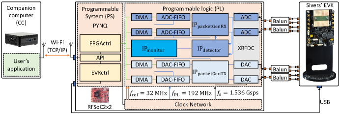
In the proposed design, RFSoC2x2 is responsible for the following tasks: 1) Generating the in-phase and quadrature signals based on the IQ samples to be transmitted; 2) Acquiring a desired number of IQ samples by sampling the baseband in-phase and quadrature signals; 3) Configuring and controlling EVK06002 over a USB port; and 4) Providing a TCP/IP-based API for CC. These tasks are managed by the objects , , and , running in PYNQ. For the first and second tasks, interacts with the IPs in the PL via advanced extensible interface (AXI). It manages multi-tile synchronization (MTS) with a specific clock distribution, IQ data acquisition or transmission, and WTR. For the third task, uses publicly available PyFtdi library and provides a basic set of functions to read and set the registers of EVK06002. For the last task, uses socket library and establishes a TCP/IP connection with CC. It provides a set of instructions to the CC to control the radio. The proposed architecture and the implemented SDR are shown in Figure 1.
III Programmable Logic and System Design
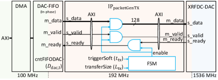
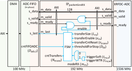
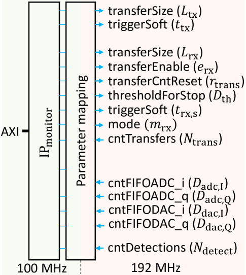
In this section, we introduce the developed IPs and discuss how they are utilized. In addition to Xilinx RF data converter (XRFDC) (contains both ADCs and DACs), Xilinx AXI first-in-first-out (FIFO), and Xilinx AXI direct-memory access (DMA) blocks, we develop four main IPs to maximize the flexibility of the proposed SDR. controls the IQ data transfer from the DAC FIFOs to the XRFDC. manages the IQ data transfer from the XRFDC to the ADC FIFOs. detects the trigger waveform for WTR. configures and reads the registers of , , and FIFOs. We use MATLAB HDL Coder Toolbox to develop each IP. The input/output ports of these IPs are shown in Figure 2 and their functions are described in the following subsections.
We consider a clock distribution that allows the ADCs (or DACs) on different tiles of XRFDC to sample the in-phase and quadrature signals (or to convert the IQ samples to continuous-time signals), simultaneously. To this end, we use the MTS feature of Xilinx RFSoCs and generate the two reference clocks (i.e., analog and digital reference clocks) at MHz, MHz for PL, and GHz for the sample clocks.111Xilinx recommends the reference clocks for MTS to be less than 10 MHz. For our design, the MTS is maintained more accurately for 32 MHz. The reference clocks are utilized to measure the latency and offset between the sampling instances of ADCs (or DACs) based on Xilinx’s guidelines on MTS. We set the decimation and interpolation factors to 1. Hence, the sample rate of the ADCs and the DACs are Gsps. As a result, the clock distribution allows the proposed SDR to transmit or receive an arbitrary waveform with 1.536 GHz bandwidth maximum at Nyquist rate with an IQ modulator.
It is worth nothing that the XRFDC operates with a clock rate that is times faster than the one for the PL. Hence, and pushes or pulls in-phase and quadrature samples concurrently for each PL clock, where each sample is represented with 16 bits. If a higher is needed for a specific experiment, either more parallel structures need to be introduced to the PL or needs to be increased to keep constant, i.e., a trade-off between the FPGA resources and the clock rate.
III-A Transmission
For the transmission, we employ two AXI FIFOs, i.e., DAC-FIFOs, for in-phase and quadrature samples, where their depths and widths are set to and bits, respectively. Hence, the proposed SDR ensures the transmission of an IQ data of length without an underflow. The steps for transmitting IQ samples are as follows.
Step 1: pads zeroes to the IQ data, where denotes the least positive remainder.
Step 2: writes the padded IQ data samples to the DAC-FIFOs via DMAs.
Step 3: sets the transfer size as .
Step 4: triggers the transmission with the rising-edge of , i.e., by changing its state from to .
Step 5: With the trigger, enables XRFDC to read IQ samples for times from the DAC-FIFOs.
In this study, all transmissions are initiated by the PS. Also, sets or reads the registers and via .
III-B Reception
Similar to the transmission, two AXI FIFOs, called ADC-FIFOs, for in-phase and quadrature samples are employed, where their depths and widths are and bits, respectively. Hence, an IQ data of length can be acquired without an overflow. We introduce two modes, i.e., software-triggered reception (STR) and WTR, controlled by the flag , as follows.
III-B1 Software-triggered reception
If is set to , the data acquisition is triggered by the PS. This mode is useful for the measurement of existing signals in the environment. In this mode, IQ samples are received via the following steps:
Step 1: sets the transfer size as and enables the acquisition by setting the flag to .
Step 2: triggers the acquisition with the rising-edge of the flag .
Step 3: With the trigger, enables ADC-FIFOs to pull IQ samples for times.
Step 4: marks the last sample via mlast flag.
Step 5: reads the IQ samples from the ADC-FIFOs via DMAs.
Step 6: drops the last samples to match with .
III-B2 Waveform-triggered reception
For , the acquisition is intended222For , the acquisition can be still triggered by the PS via since this feature can be useful for certain applications or tests. to be triggered by upon the detection of waveform . The steps for WTR are as follows:
Step 1: configures the transfer size for each transfer and set the threshold to avoid overflow.
Step 2: The constantly searches for the trigger waveform with a set of poly-phase detectors. If one of the PPDs detects the trigger waveform , it rises .
Step 3: With the trigger, if there is enough room in the ADC-FIFOs, enables ADC-FIFOs to pull IQ samples for times. Hence, the IQ samples following upon the detection instant are pulled to the ADC-FIFOs.
Step 4: marks the last sample and increases by to indicate the number of transfers to the PS.
Step 5: reads . If , can read the IQ data samples from the ADC-FIFOs via DMAs.
As compared to STR, the main difference of WTR is that the trigger source is the PL. Hence, the data flow needs to be managed by the PL. In this study, the PS sets and the PL checks if holds to ensure that there is enough room in the ADC-FIFOs for the next transfer, where is the read counter of one of the ADC-FIFOs. Note that can reset via and flush the ADC-FIFOs at any time. The registers , , , , , , and are set or read via .
Buffer mechanism for discontinuous transmissions
One of the unique features of the WTR is that it allows discontinuous transmissions, i.e., it enables ADC-FIFOs to store transfers in the ADC-FIFOs, where the receptions depend on the transmission instants. This feature is particularly useful for increasing the speed for CC-based beam sweeping. For example, consider a scenario where the transmitter transmits a set of IQ samples of length to identify the best AWV in a beambook of size . Let the IQ samples encode the utilized AWV index. By transmitting the corresponding waveform along with the trigger waveform at different times and using WTR at the receiver for , among 64 transmissions, only the ones detected by the PPDs are written to the ADC-FIFOs. Once the transmissions are completed, the CC at the receiver side reads (i.e., Step 5 in Section III-B2) to identify how many successful receptions (or transfers) is occurred. By pulling and processing the corresponding IQ data samples, the CC can decode the beam indices and identify the best AWV at the transmitter without continuously monitoring the IQ samples. We use this scenario for our experiment as discussed in Section IV.
Trigger waveform and detector
We design the trigger waveform and its detection based on the strategy in [9]. In this method, the sequence is a single-carrier (SC) waveform with the roll-off factor of synthesized by upsampling a repeated binary phase shift keying (BPSK) modulated sequence, i.e., , by a factor of and passing it through a root-raised cosine (RRC) filter, where is a binary Golay sequence. As a result, the null-to-null bandwidth of is equal to MHz. In [9], the design of is motivated as follows: 1) A cross-correlation operation with this waveform can be realized by using an approximate waveform where its samples are either or . This feature leads to better utilization of FPGA resources since the multiplications can be reduced to additions or subtractions. 2) By detecting the presence of shorter sequence g back-to-back four times, the distortion due to the carrier frequency offset can be circumvented. 3) A smaller dynamic range with SC waveform requires less power back-off. The metric that is used for the detection of g can be expressed as:
| (1) |
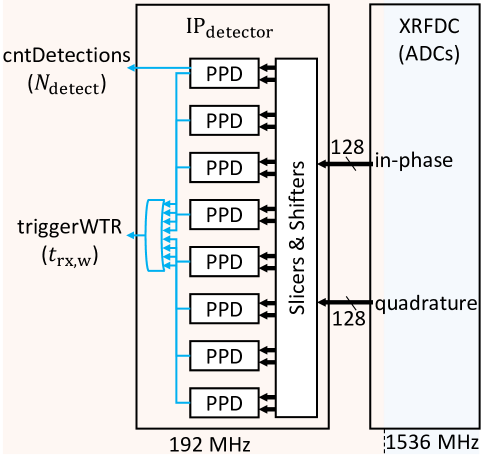
where is based on the aforementioned approximate SC waveform with the rectangular filter and equal to for and , where is the th received IQ sample. A PPD declares a detection if is larger than 1/4 for four times with 128 samples apart. We also implement a counter for the first PPD to monitor the number of detection events, i.e., , for test purposes.
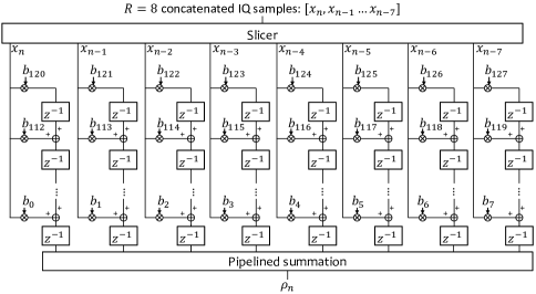
XRFDC provides in-phase and quadrature samples concurrently for each PL clock due to the difference between the PL clock and ADC sample rate. Hence, we implement the cross-correlation operation in (1), i.e., , as a finite impulse response (FIR) filter and exploit the following identity to calculate the result for every other samples:
| (2) |
for . As can be seen from (2), for each PL clock, can be obtained by summing the outputs of sub-FIR filters, i.e., , where the input of the th sub-filter is the th sample of IQ samples provided by XRFDC. We implement the FIR filter by using the transposed form of each sub-filter with pipelining, as illustrated in Figure 3. To detect , we use parallel PPDs that operate on different lags. If one of the PPDs detect , the flag is raised.
III-C Application-programming interface
The CC interacts with the proposed SDR via the instruction set defined in the object. We define two TCP/IP ports for control and data. While control port is utilized to transfer commands and acknowledgments, the data port is utilized to exchange IQ samples. With the developed API, the AWVs, AWV indices, carrier frequency, and gains can be controlled by the CC. The details related to the instruction set in the API are omitted due to the page limitation.
IV Beam Sweeping Experiment
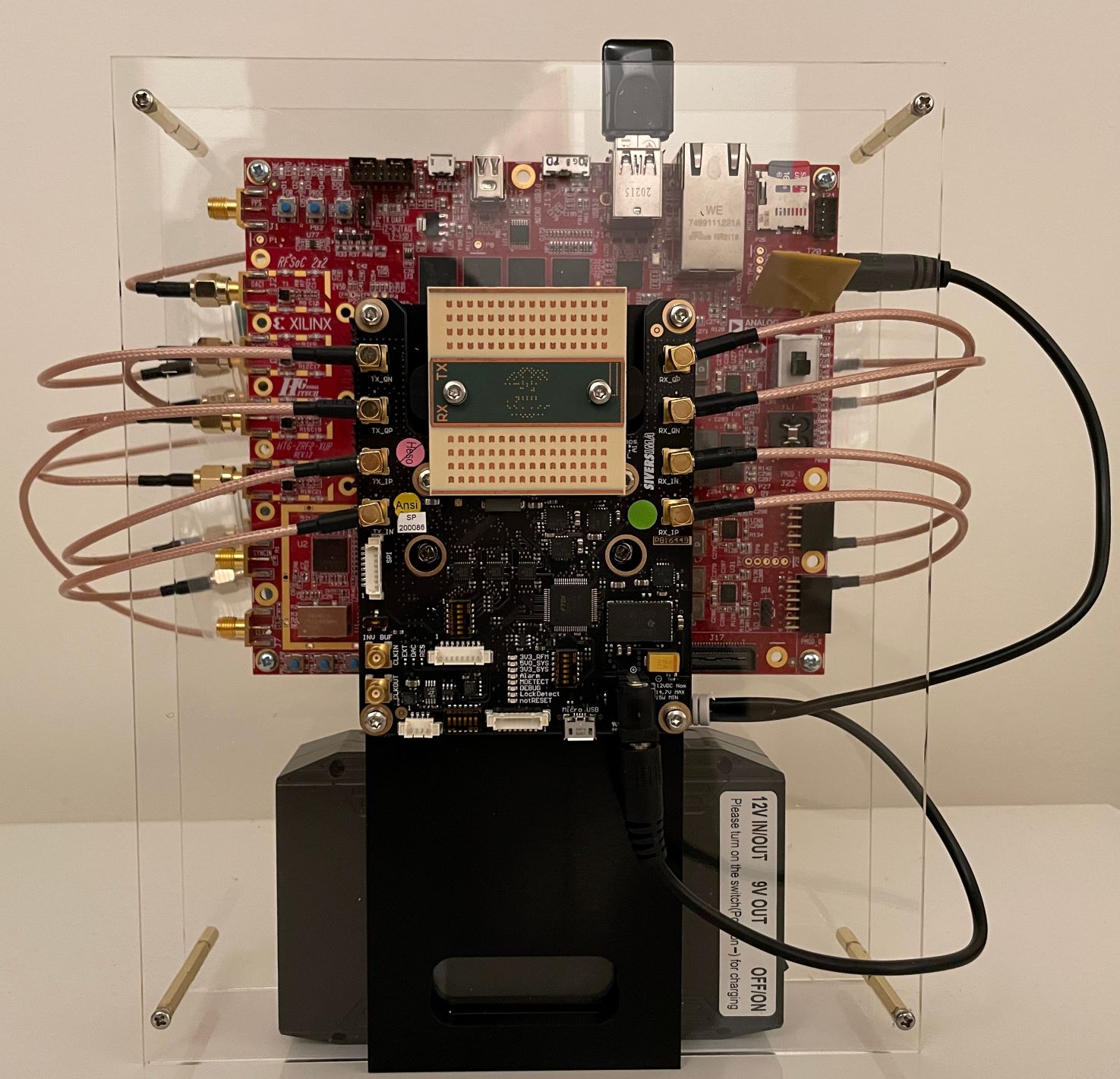
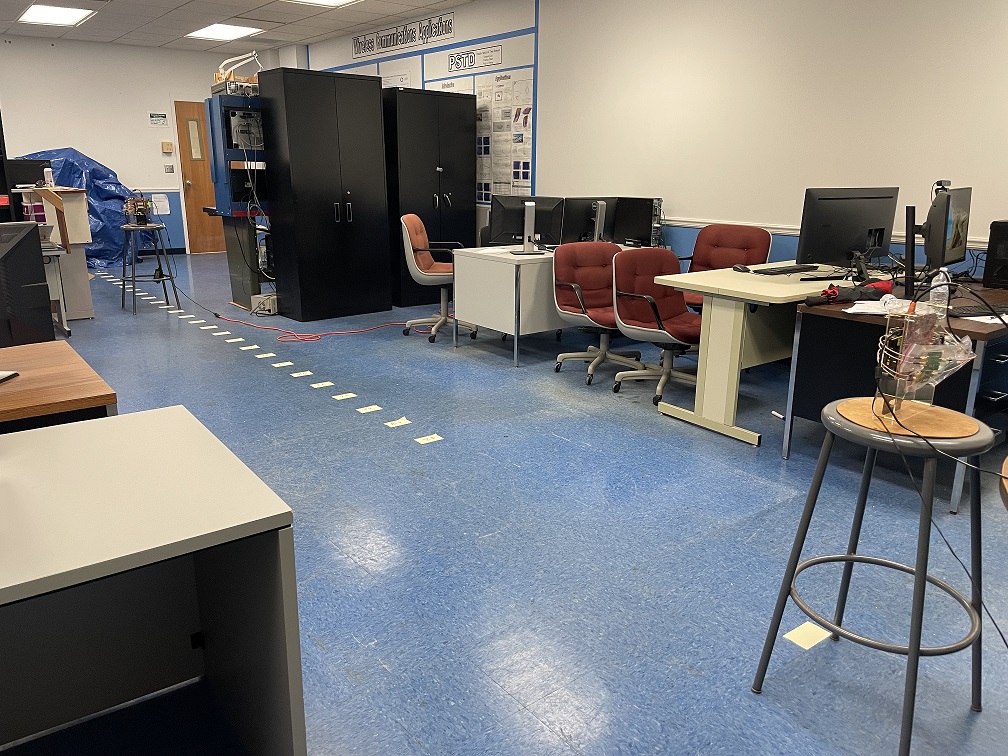
In this study, we demonstrate the WTR and the buffering method for discontinuous transmission with a beam sweeping experiment in an indoor office environment. In the experiment, we use one fixed SDR and a mobile SDR, where the SDRs face each other, as can be seen in Figure 4LABEL:sub@subfig:env. Each SDR is controlled by a CC over an access point (AP). As illustrated in Figure 4LABEL:sub@subfig:connections, the mobile SDR is controlled over the wireless local-area network (WLAN) since a wireless control allows us to adjust the mobile SDR’s position conveniently in the experiment. We reduce the link distance between the SDRs, denoted by , from 9.75 m to 2.44 m with a spacing of 12" (i.e., 25 locations). We use the default customizable set of 64 AWVs for GHz, provided by Sivers, sweeping the azimuth between and uniformly (i.e., side wall to side wall). Hence, in total, there exist 4096 TX-RX AWV index pairs one can choose for the mmWave link. Our goal with the experiment is to evaluate the signal-to-noise ratio (SNR) for each pair at different locations for GHz.

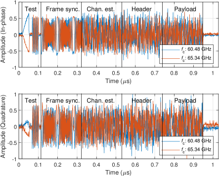
We implement the following routine to calculate the SNR for a given TX-RX AWV index pair. The CC of the mobile SDR first sets the TX AWV index. It then generates an orthogonal frequency division multiplexing-based physical layer protocol data unit (PPDU) [9], where the data bits indicate the utilized TX AWV index. The PPDU consists of four OFDM symbols for synchronization, channel estimation, header data, and payload and its length is complex samples. The CC transmits the PPDU along with a test waveform and the trigger waveform , where the test waveform consists of a ramp waveform ( samples), zero samples ( samples), a tone ( samples), and zero samples ( samples) for evaluating potential impairments, visually. After the transmission, the CC increases the TX AWV index and repeats the aforementioned announcement procedure. In our experiment, the CC completes the announcements of 64 TX AWV indices in less than 2 sec. The fixed SDR utilizes WTR. The corresponding CC first sets the RX AWV index. It waits for 2 sec and reads . For each transfer, it then pulls the corresponding IQ samples (1580 samples) and tries to decode the PPDU. If the decoding is successful, the CC detects announced TX AWV index and measures the SNR. It is worth noting we do not implement any exhaustive correlation in the CC to find the transmitted PPDU, thanks to the WTR. With this procedure, we record the IQ data for all transfers for a given RX AWV index, location, and and generate a dataset.
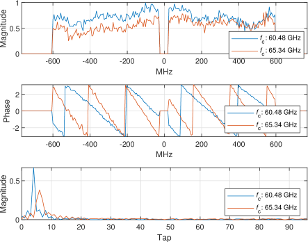
In Figure 5, as an example, we show the received IQ data samples and the measured channel frequency response (CFR) and channel impulse response (CIR) for the 29th transfer (60.48 GHz) and 20th transfer (65.34 GHz) when the RX AWV is 31 and the link distance is 9.75 m. After decoding the PPDU, TX AWV index is detected as 50 for both cases and the measured SNRs are calculated as 25.76 dB and 24.03 dB for GHz and GHz, respectively. The measured CFRs are relatively flat and similar, where the gap in the measurement is due to the null DC subcarriers. At the beginning of the IQ data, we also observe the test waveform.
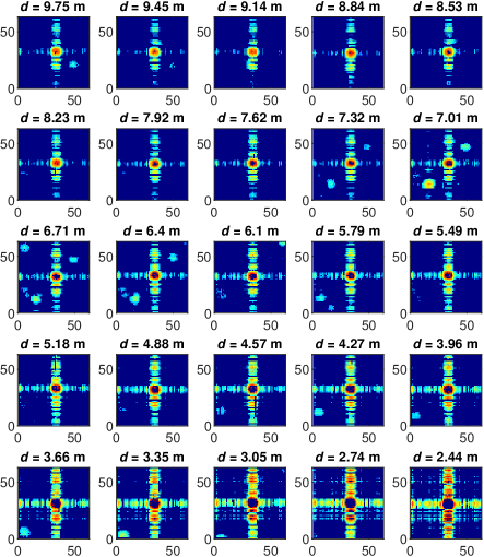
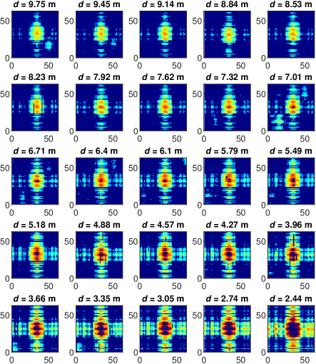
In Figure 6, we provide the SNRs for a given TX-RX AWV index pair at different locations. We can infer the following. First, the SNR can reach up to 30 dB when the beams are well-aligned, e.g., when the RX AWV and TX AWV indices are around 32, i.e., degrees. Second, if the received signal is powerful, the receiver may not be able to decode the PPDU due to saturation. We use fixed TX and RX gains in the experiment. Third, the link can still be maintained over a reflection. For instance, for GHz and m, it is possible to maintain the link if both TX AWV and RX AWV indices are set to 13, likely over a reflection due to the metal cabinets. Fourth, we observe a large difference in the SNR matrices when is switched to GHz. Since we still use the AWVs for GHz, the beams are not focused for GHz. While the mismatch allows the link via the antenna side lobes, it becomes more blind to the reflections as the power is dispersed to the different angles.
V Concluding Remarks
In this study, we propose a mmWave SDR solution for experimentation in the 60 GHz band and introduce WTR and a buffering approach for discontinuous transmission to achieve a flexible CC-based baseband signal processing. We also generate a new dataset based on a beam sweeping experiment. The main advantages of the proposed SDR are that it is low-cost, portable, and easy to construct. Also, we provide the source code publicly for further development. In future work, we will extend the proposed SDR by integrating and testing it with UAVs in the NSF AERPAW platform at 28 GHz. In particular, we will focus on beam steering experiments to support links with a mobile UAV. Development of burst type of transmission along with WTR, the potential use of onboard RAM for longer recording, and leveraging the UAV mobility for achieving wide-angle beam sweeping are several possible areas that we will investigate. We will develop a digital twin, emulating the UAVs in conjunction with the proposed SDRs and develop suitable channel models for this environment.
Acknowledgment
The authors would like to thank Brian A. Floyd for his contributions to the discussions on the RF design.
References
- [1] R. Zhao, T. Woodford, T. Wei, K. Qian, and X. Zhang, “M-Cube: A millimeter-wave massive MIMO software radio,” in Proc. ACM MobiCom, New York, NY, USA, 2020.
- [2] T. Chen, P. Maddala, P. Skrimponis, J. Kolodziejski, X. Gu, A. Paidimarri, S. Rangan, G. Zussman, and I. Seskar, “Programmable and open-access millimeter-wave radios in the PAWR COSMOS testbed,” in Proc. ACM WiNTECH, New York, NY, USA, 2021, pp. 1–8.
- [3] J. O. Lacruz, R. R. Ortiz, and J. Widmer, “A real-time experimentation platform for sub-6 GHz and millimeter-wave MIMO systems,” in Proc. ACM MobiSys, New York, NY, USA, 2021, pp. 427–439.
- [4] R. Zavorka, R. Marsalek, J. Vychodil, E. Zochmann, G. Ghiaasi, and J. Blumenstein, “Deep neural network-based human activity classifier in 60 GHz WLAN channels,” in Proc. IEEE GLOBECOM Workshops - Workshop on Propagation Channel Models and Evaluation Methodologies for 6G, Dec. 2022, pp. 1–6.
- [5] N. N. Santhi, M. Polese, and T. Melodia, “An end-to-end programmable testbed for the experimental evaluation of video streaming at mmWaves,” in Proc. IEEE GLOBECOM Workshops - Workshop on High Capacity Wireless Communications, Dec. 2022, pp. 1–6.
- [6] M. S. Sim, S. Ahuja, A. D. Wooseok Nam, Z. Fan, and T. Luo, “60 GHz mmWave full-duplex transceiver study and over-the-air link verification,” in Proc. IEEE GLOBECOM, Dec. 2022, pp. 1–6.
- [7] A. Şahin, “IQ data for a given TX-RX beam index pair for link-level analysis in the 60 GHz band,” 2023. [Online]. Available: https://dx.doi.org/10.21227/cm3m-2f84
- [8] ——, “Project: mmWaveSDR,” https://github.com/alphansahin/mmWaveSDR, 2023.
- [9] A. Şahin and R. Yang, “A demonstration of over-the-air-computation for FEEL,” in Proc. IEEE GLOBECOM Workshops - Workshop on Wireless Communications for Distributed Intelligence, Dec. 2022, pp. 1–6.