Oops..! I Glitched It Again!
How to Multi-Glitch the Glitching-Protections on ARM TrustZone-M
Abstract
Voltage Fault Injection (VFI), also known as power glitching, has proven to be a severe threat to real-world systems. In VFI attacks, the adversary disturbs the power-supply of the target-device forcing the device to illegitimate behavior. Various countermeasures have been proposed to address different types of fault injection attacks at different abstraction layers, either requiring to modify the underlying hardware or software/firmware at the machine instruction level. Moreover, only recently, individual chip manufacturers have started to respond to this threat by integrating countermeasures in their products. Generally, these countermeasures aim at protecting against single fault injection (SFI) attacks, since Multiple Fault Injection (MFI) is believed to be challenging and sometimes even impractical.
In this paper, we present -Glitch, the first Voltage Fault Injection (VFI) platform which is capable of injecting multiple, coordinated voltage faults into a target device, requiring only a single trigger signal. We provide a novel flow for Multiple Voltage Fault Injection (MVFI) attacks to significantly reduce the search complexity for fault parameters, as the search space increases exponentially with each additional fault injection. We evaluate and showcase the effectiveness and practicality of our attack platform on four real-world chips, featuring TrustZone-M: The first two have interdependent backchecking mechanisms, while the second two have additionally integrated countermeasures against fault injection. Our evaluation revealed that -Glitch can successfully inject four consecutive faults within an average time of one day. Finally, we discuss potential countermeasures to mitigate VFI attacks and additionally propose two novel attack scenarios for MVFI.
1 Introduction
Fault Injection (FI) has proven to form a powerful threat to various computing platforms. All fault injection methods temporarily disturb the physical runtime environment of the Device under Test (DuT) to cause specific misbehavior. Common FI attacks are, e.g., conducted by disturbing the supply voltage [3], generating malicious clock signals [49], rapidly changing the electromagnetic environment [28], or inducing a light pulse at the decapsulated Integrated Circuits (ICs) [59]. The possible consequences from injecting a certain type of fault are described by a FI method’s Fault Model. Depending on the specific FI method used, the corresponding Fault Model may, e.g., be defined as skipping of machine instructions [41], corrupting the instruction decoding [55] or altering the data stored on a device’s internal memory [33]. Hence, FI attacks are capable of introducing vulnerabilities. As an example, this kind of attacks have been successfully launched on Trusted Execution Environments (TEEs) [16, 36], embedded devices [40, 63], smart cards [59] and recently even against workstation processors [14, 23].
A popular class of FI and the focus of this paper is Voltage Fault Injection (VFI), as this approach is very versatile while exhibiting a high impact attack vector. VFI disturbs a DuT’s power supply to provoke a specific malfunction. To address VFI attacks, a variety of software- [4, 48, 32, 5] as well as hardware-based [61, 50] countermeasures have been proposed over the years. Fortunately, the industry has recognized the severity of fault injection attacks and individual manufacturers are reacting to it by integrating countermeasures into their products. For instance, NXP recently released multiple ARMv8-M series Microcontroller Units (MCUs), which feature an instruction-level FI countermeasure to protect some of their security-critical registers from FI attacks. Moreover, ARMv8-M MCUs that feature TrustZone-M (e.g., STM, Atmel, NXP) are equipped with a novel hardware unit on the internal bus system, performing additional checks on every bus access, in order to ensure the security properties of the TEE. Although not explicitly aimed to mitigate FI attacks, this backchecking mechanism has complex interdependencies which make FI attacks targeting TrustZone-M, highly difficult [46]. Typically, FI attacks and countermeasures are dedicated to Single Fault Injection (SFI), although Multiple Fault Injection (MFI) seems to be much more powerful. In MFI, multiple, coordinated faults of a certain type are injected after a single synchronizing trigger signal, in order to attack multiple target instructions during a single execution. MFI could theoretically be used against instruction-level based countermeasures [32, 4], however, as stated by previous work conducting those attacks, especially Multiple Voltage Fault Injection (MVFI) are considered highly impractical due to the lack of precise and affordable MFI tools [4, 46] and efficient parameter search algorithms. Even though, commercial equipment for MFI is available, devices from e.g., Alphanov111https://www.alphanov.com/en/products-services/double-laser-fault-injection and Riscure222https://www.riscure.com/blog/security-highlight-multi-fault-attacks-are-practical were shown only to conduct Multiple Laser Fault Injection (MLFI) which is much more resource intensive than MVFI. In addition, off-the-shelf VFI devices from NewAE [44] are not capable of injecting multiple faults based on a single trigger. In this paper we address this open problem by providing a highly precise MVFI tool and the corresponding efficient parameter search algorithms, which enable an adversary to inject multiple, coordinated and consecutive voltage faults into any target device in order to attack any software-based SFI protection on the instruction-level. We show that our tool is able to successfully perform a parameter search for up to four consecutive voltage faults and perform MVFI to skip the corresponding instructions in about one day.
To realize this, we had to overcome a number of challenges: First, to the best of our knowledge, there exists no tool to conduct MVFI, so we designed and built our framework, coined -Glitch. Second, the timely effort required to search for multiple fault parameters grows exponentially with each additional fault, if a traditional fault parameter search (i.e., an exhaustive search) is used. Hence, we designed, implemented and evaluated novel approaches, to search for multiple fault injection parameters, which are efficient enough for MVFI setups.
Even though our approach can be used to attack arbitrary devices, we focus on attacking TrustZone-M (TZM), as TEEs form highly secure targets, which when compromised have shown to lead to the disclosure of highly sensitive information [47]. While principally -Glitch can defeat many VFI research proposal countermeasures, as discussed in section 9. However, we evaluate -Glitch on four real-world example MCUs as most academic proposals are not open sourced. As a Proof-of-Concept (PoC) we attack two TZM MCUs which have protections explicitly protecting against FI attacks. Therefore, it cannot be successfully attacked by means of SFI. We also attack two other ICs with a subset of protections. Our main contributions are as follows:
- Novel MFI Framework
-
We present -Glitch, a novel fault injection framework, which is capable of injecting multiple, coordinated voltage faults into any DuT, in order to overcome FI countermeasures implemented on the instruction level.
- Parameter Search Algorithm
-
We explore the impact of additional faults on the search space spanned by the combinations of multiple fault’s parameters and present a novel and effective multiple fault parameter search to overcome the exponential increase in needed resources introduced by conventional algorithms. Our approach exhibits a 50 times speedup when searching for two consecutive voltage fault’s parameters, and an 8.3 time speedup when searching for four voltage fault’s parameters.
- Real-world Attack
-
We use -Glitch in order to inject multiple voltage faults into NXP’s LPC55SXX and RT6XX MCU and hereby successfully circumventing all FI protections. By this, we are able to fully compromise the security introduced by TZM, by accessing the secure memory from within non-secure firmware. We show that this attack can be performed within an average time of one day. Further, we show that other TZM ICs can be broken using a subset of faults required for NXP ICs.
- Possible Countermeasures
-
We propose a software level enhancement to the existing countermeasures, which is capable to protect from MFI attacks, by eliminating the possibility to search for MFI parameters.
Responsible Disclosure
The results of this work have been responsibly disclosed to NXP Semiconductors Ltd. A response acknowledging our findings has been received. In follow up communication the authors are collaborating with NXP Semiconductors Ltd. on finding a security patch. The authors would like to thank NXP Semiconductors Ltd. for their timely and professional communication following the responsible disclosure of our findings.
2 Background
In the following we provide the background necessary in order to understand this work.
2.1 Voltage Fault Injection
Voltage Fault Injection (VFI) is a specific Fault Injection (FI) method to inject disturbances into the power supply line of an Integrated Circuit (IC) and hence, violates the IC’s specified operating conditions for a certain, controlled period of time. Most ICs, like Microcontroller Units (MCUs), expect their supply voltage to be stable and steady, i.e., there should be no point during runtime, at which the supply voltage is interrupted or leaves a specified operating range.
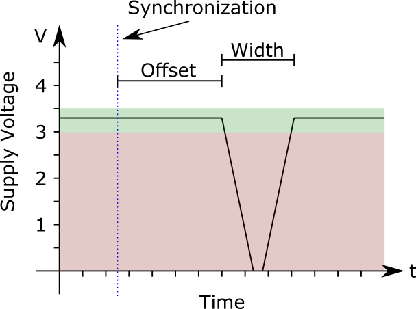
Figure 1 depicts a single voltage fault injected into the supply line of an IC running at . Here the specified operating supply voltage range is highlighted green ( to ), whereas the red highlighted range ( to ) indicates, that the operating conditions are violated. The fault voltage level is most commonly defined as the Ground (GND) reference, however, this may be optimized with respect to either reliability and repeatability [9] or timely resolution [24]. A voltage fault is parameterized by it’s Offset w.r.t. a synchronization point, and it’s Width [40]. In every VFI experiment the most complex part is to find the best fault parameters, in order to provide a reliable and repeatable attack [12].
The Fault Model
of VFI on MCUs consists of four different behaviors, which all arise from the effects of VFI on the processors internal pipeline stages namely, skipping of machine instructions, corrupting data fetches, corrupting instruction decodes and corrupting write-backs. Throughout this work we focus on applying VFI in order to skip machine instructions. In this context, we further define the Fault Target as the machine instruction the adversary aims to skip, in order to cause a specific misbehavior. Moreover, a Fault Target is assumed to be hit, once it is successfully attacked by injecting a fault.
Fault Injection Setups
can be divided into two main classes of Cooperative FI and Non-Cooperative FI [42]. In the former, the attacker is able to reprogram the Device under Test (DuT). Here, the attacker commonly implements a protocol to communicate with the device. By this it is possible to, e.g., call a subroutine on the device that shall be tested against FI, by issuing a corresponding command. In addition, in cooperative FI, the DuT is notifying the FI framework when entering the code region to be tested by asserting the synchronizing signal, referred to as Trigger. Cooperative setups are commonly encountered in Proof-of-Concepts (PoCs). In the latter the adversary is unable to reprogram the DuT. Non-Cooperative FI is commonly encountered in attack scenarios, which focus on attacking proprietary targets.
3 Adversary Model
The adversary model includes a physical access attacker. Further, the adversary is capable of performing slight modifications to the DuT in order to make VFI possible, similar to related literature [40] (e.g., attaching copper wires, detaching bypass-capacitors). In order to define Fault Targets, the adversary has some knowledge about the targets firmware, which may be, e.g., through the use of a public library [41] or a previous binary firmware disclosure [60].
4 -Glitch Design
In this section, we present our novel Multiple Fault Injection (MFI) design, named -Glitch.
Similarly to Single Fault Injection (SFI) attacks, we adopt the high-level flow, which consists of defining the experiment success function, performing fault injection by exhaustively searching the fault’s parameters and analyzing and comparing success rates333https://github.com/newaetech/chipwhisperer-jupyter/tree/92307484b155394a01c7021f1d21123efccee4aa/courses/fault101.
The complexity of searching multiple fault parameters at once increases exponentially by every additional fault, using conventional parameter search algorithms. Therefore, we introduce our novel, efficient sweeping approach to be used in MFI setups.
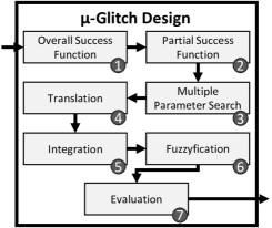
The overall attack flow is depicted in Figure 2:
-
1.
Define Overall Success Function:
In order to decide about the outcome (i.e. overall success or failure) of a MFI attempt, a Success Function (SF) has to be defined. This is a binary function which is evaluated in later steps in order to indicate either a success, if and only if all the Fault Targets are hit at once or a failure in all other cases. -
2.
Define Partial Success Functions:
The parameter search needs to distinguish between hit Fault Targets. This is achieved by defining Partial Success Functions (PSFs), which are needed to recognize, if some, but not all, Fault Targets have been hit, whereas the SF only allows to determine, if all the Fault Targets have been faulted during a single, consecutive execution. -
3.
Perform Multiple Parameter Search:
The goal of performing the Multiple Parameter Search is equal to this of the Parameter Search in SFI, i.e. valid fault parameters have to be discovered, which lead to an experiment success. Even though there are multiple such parameter pairs to be discovered throughout this step, the process of finding the right parameters is similar to the one in SFI: The adversary uses a single fault in order to search in an increased space, spanned by all Fault Targets parameters. We refer to this process as sweeping. As PSFs have previously been defined, when the injected fault hits one of the Fault Targets, it will be detected by evaluating the corresponding PSF.As there is only a single fault per execution injected, the SF is not evaluated during this step. The result is a set of sets of absolute parameters, i.e., one set per Fault Target, absolute to a common synchronization Trigger.
-
4.
Translating Absolute Parameters:
The previously discovered absolute fault parameters need to be translated into relative parameters (i.e., relative to the preceding fault), by using the inductive definitions in Equation 1 and Equation 2.(1) (2) That is, the first faults relative Offset is always equal to the first absolute Offset found by our sweeping approach. Every additional fault’s relative Offset is defined recursively in terms of its absolute Offset , its previous global Offset and the previous fault’s width . All the fault’s Widths may be directly adopted.
-
5.
Fuzzyfy Parameters:
Due to the non-deterministic behavior of the Device under Test (DuT) in the presence of voltage faults, every preceding fault may affect its succeeding ones parameters in unpredictable ways. In order to address this uncertainty, slight modifications have to be applied to the relative Offsets. We refer to this process as fuzzyfication. Here, every fault’s Offset is not considered a single value, but rather a very small interval bound by . The hereby generated intervals serve as input for the following integration step. -
6.
Integrate Fuzzyfied Parameters:
As the uncertainty and hence the provided sets are considered to be very small, it is viable to perform an exhaustive search on multiple fault’s parameters. As all the required voltage faults are hereby injected at once, this represents the first step in which the actual attack is performed. Therefore, each MFI attempt is evaluated based on the overall SF, instead of the PSFs. -
7.
Evaluate and Analyze Repeatability:
Finally, analyzing combinations of multiple fault’s parameters, which in combination led to an overall success is needed. Further, if there are multiple such combinations available, the different combinations have to be qualified and compared w.r.t. their success rates.
4.1 Transforming Non-Cooperative Setups
-Glitch is also able to cope with non-cooperative setups, in which there are no PSFs definable, by transforming non-cooperative setups to cooperative ones. In general, an adversary can perform parameter search on a physical identical, but cooperative setup, before transferring the identified parameters to the non-cooperative setup, as in this case defining PSFs is easy [43]. This approach is feasible whenever the firmware can (partly) be reproduced and the offset in between Fault Targets remains constant.
As every Integrated Circuit (IC) manufacturer (e.g., STM, Atmel and NXP) provide their own Software Development Kit (SDK) in order to generate the machine instructions for the target device, and it is considered to be best practice and highly encouraged by the manufacturers to use this example code to set up TrustZone-M (TZM), every non-cooperative setup using these public SDKs can be transformed to a cooperative one in the sense of the parameter search.
Therefore, in such a scenario it is possible to transfer the parameters of several Fault Targets to a non-cooperative setup, thus reducing complexity drastically and enable attacking proprietary black-box software on these devices.
5 -Glitch Attack on TrustZone-M
In this section we describe a real-world attack on TrustZone-M (TZM) using -Glitch, as compromising these highly secured environments usually leads to the disclosure of sensitive information. The goal of our attack is to leak secrets stored in secure memory of the TZM from within non-secure firmware. Even though -Glitch is able to circumvent all duplication based instruction-level countermeasures, as stated in section 9, we chose to attack the duplication based protection of NXP. NXP is an Integrated Circuit (IC) manufacturer, which recently adapted Fault Injection (FI) countermeasures similar to protections proposed by academia in their real-world threat modeling processes for their ARMv8-M series Microcontroller Units (MCUs). The chips are protected by implementing a modified version of the duplication based approach of Barenghi et al. [4], which is referred to as Duplicate Registers [38, 39]. We will elaborate this in more detail in subsubsection 5.2.1. We also evaluate this attack on other ARMv8-M MCUs (namely, STM32L5 and Atmel SAML11) which can be compromised with a subset of Fault Targets of this attack. First, we provide preliminary background on TZM.
5.1 TrustZone-M Background
TZM is a Trusted Execution Environment (TEE) for embedded processors, i.e., it introduces system wide hardware-enforced computation and memory isolation mechanisms, which are built directly into the processor. The TZM platform is configured by different memory attribution units, which are elaborated in the following and depicted in Figure 3.
The Security Attribution Unit (SAU)
is specified and designed by ARM. Here, it is possible to define up to eight different memory regions which can be either Secure (S), Non-Secure (NS) or Non-Secure Callable (NSC). The final security state of a memory region, is defined in conjunction with the Implementation Defined Attribution Unit (IDAU).
The Implementation Defined Attribution Unit (IDAU)
is specified by the corresponding IC manufacturer. It defines memory regions to be either S or NS. Defining NSC is a privilege granted exclusively to the SAU. On most of the commercially available ARMv8-M TZM processors the IDAU is implemented to perform a bit check on the bit of a requested address. For an arbitrary address, the IDAU returns S if the bit is set, otherwise NS.
The final Security State
is determined by the strongest output security state from SAU and IDAU for a requested address, where the partial order of holds.
The Transition between S and NS
takes place based on novel ARMv8-M instructions. The non-secure code is linked against a set of function headers, called the veneer table, which is exported during compilation of the S firmware. To switch from NS to S, it is required to take a detour through calling a veneer function in a NSC region, which consists of a Secure Gateway (SG) instruction444https://developer.arm.com/documentation/100690/0201/Switching-between-Secure-and-Non-secure-states.
To switch from S to NS, it is necessary to use either the Branch with eXchange to Non-Secure state (BXNS) or the Branch with Link and eXchange to Non-Secure state (BLXNS) instruction. Here it is important to note, that the security level transition will only happen, if the Least Significant Bit (LSB) of the NS address is unset555https://developer.arm.com/documentation/100235/0004/the-cortex-m33-instruction-set/branch-and-control-instructions/bxns-and-blxns.
The Backchecking Mechanism
represents a TEE protection available on MCUs featuring TZM, which ensures confidentiality and integrity on a system level. In this concept, additional integrity checks are realized by introducing new hardware units on the internal system bus, referred to as Advanced High-Performance Bus (AHB).
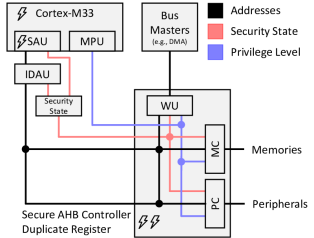
The three novel hardware units residing on the AHB matrix are:
- Wrapper Units (WUs)
-
are used to wrap TZM unaware bus masters to signal side-band information on the AHB matrix. This additional information determines the Security State and the Privilege Level for a requested address. Based on this information, the Checker Units perform additional checks upon every bus access.
- Memory Checkers (MCs)
-
are used to protect memory devices, such as Flashes, Random Access Memorys (RAMs) and Read-only Memorys (ROMs) from unintended access of an application.
- Peripheral Checkers (PCs)
-
are used to protect the peripherals which are directly connected to the AHB or via Advanced Peripheral Bridge (APB) from unintended access of an application.
NXP refers to this concept as Secure AHB Controller [38], STMicroelectronics to Global TrustZone Controller (GTZC) [52] and Atmel to Peripheral Access Control (PAC) [1].
5.2 Attack Internals
Throughout this section we describe our concrete attack against NXP based implementations of the TrustZone-M and their FI countermeasures.
5.2.1 NXP’s Duplicate Register
NXP’s FI countermeasure, referred to as the Duplicate Registers method, deploys for every security-critical register a second, equally structured register in memory space. If active, both of these registers are written sequentially in firmware. Once Single Fault Injection (SFI) is applied in order to skip or modify an assignment to a secured register, it’s duplicate register would afterwards still be written as intended. Based on the introduced inconsistency between original register and it’s duplicate register, any SFI attempt is detected in hardware. This advanced countermeasure is, e.g., encountered in NXP’s LPC55S6X [38] and RT6XX [39] series MCUs. We have identified Duplicate Registers being used in Debugging Features, Physical Unclonable Function (PUF) Index Configuration and the Activation of the Secure AHB Controller.
5.2.2 Interdependency of Protections
As the checks performed by SAU and IDAU and the checks performed by NXP’s Secure AHB Controller are performed sequentially, attacking only one of these checks would always be detected by the respective counterpart. In addition, the activation of the Secure AHB Controller is further protected by Duplicate Registers. Hence, in order to succeed, all of these have to be successfully attacked during one consecutive execution. While conducting our experiments, NXP processors seem to lock themselves into erroneous states, when the TrustZone-M specific instructions to switch the security context are issued, whenever the SAU is not active. Moreover, the activation of the IDAU cannot be skipped, as it is active by default after Power-On Reset (POR).
5.2.3 Fault Targets
With the FI countermeasure and interdependencies of the TZM protections in mind, we define the following Fault Targets and their technical details, which are represented by a flash symbol in Figure 3.
Activation of the Security Attribution Unit (SAU)
The SAU is activated in the TZM setup routine, a system routine that is executed before the trusted and secure user code is executed. The relevant Fault Target is depicted in line 6 of LABEL:lst:init-trustzone, and is commented with SAU_CTRL.
Once the Fault Target is hit, i.e. the STR instruction is skipped, the SAU is disabled. As later on the Secure AHB Controller is setup as intended, it would detect any invalid bus accesses due to a mismatch of the configuration of both hardware units. This inconsistency between the Secure AHB Controllers configuration and TZM configuration is what prevents a successful attack at this point.
Activation of Secure AHB Controller
To resolve this inconsistency, the adversary must prevent the Secure AHB Controller from being activated. The Fault Target that needs to be hit in order to prevent activation is shown in line 15 of LABEL:lst:init-trustzone and is commented with Original. Once this store instruction is skipped, the Secure AHB Controller is being kept deactivated. Due to the use of Duplicate Registers however, any successful FI attempt will still be detected.
Duplicate Register for Secure AHB Controller
At this point the processor would be able to detect an inconsistency between the deactivated Secure AHB Controller and its active Duplicate Register. Hence, the assignment to the Duplicate Register forms another Fault Target, which is shown in line 13 of LABEL:lst:init-trustzone and is commented with Duplicate.
Prevent Switching of Security Context
After the previous Fault Targets are all hit, the SAU and all the TZM protections are fully disabled.
After the boot process, the bootloader passes execution to S firmware, in which the TZM is configured666https://www.nxp.com/design/software/development-software/mcuxpresso-software-and-tools-/mcu-bootloader-for-nxp-microcontrollers:MCUBOOT?tab=Design_Tools_Tab. Afterwards, the main function of the user defined code sets up the system and peripherals, before ultimately passing the execution to NS code, which at this point is invalid and therefore the IC would lock itself into an erroneous state. This transition is performed by the TZM specific BXNS instruction. In LABEL:lst:security_state_transition, we present the relevant disassembled parts of the binary, generated by Gnu Compiler Collection (GCC) for transitioning from S to NS.
In order to prevent the internal security context switch from S to NS, it is sufficient to skip the shift-out shift-in operation, implemented by the LSRS and LSLS instructions defined in line 16 and 17. As this code is executed in S state, the LSB is always set.
It is worth noting that even though we have been using NXP’s toolchain to generate the firmware, the herein described privilege escalation can be performed on almost every commercial available TZM MCU, as most IC manufacturer release their toolchains based on GCC. Moreover, in ARM based compilers clearing the LSB is performed by a single bit clear (BIC) instruction.
5.3 -Glitch Hardware Framework
The Fault Targets in the Multiple Fault Injection (MFI) attack, need to be successfully hit all at once, in one continuous execution in order to fully break the security granted by NXP’s TZM implementation. A lack of suitable commercial MFI tools led to the development of our -Glitch MFI framework, which will be introduced throughout this section.
Our custom MFI framework consists of six components, namely the Clock Generation Unit, the Host Communication Unit, the I/O Buffer Unit, internal Configuration Registers, the Multiple Voltage Fault Unit and the Serial Target I/O Unit. In the following, we elaborate the Multiple Voltage Fault Unit in more detail, as it represents one of the main parts of our framework. However, in order to introduce our MFI hardware, it is important to first understand the Single Fault Unit (SFU) design, which is commonly encountered in SFI setups777https://github.com/chipfail/chipfail-glitcher/tree/master/chipfail-glitcher.srcs/sources_1/new.
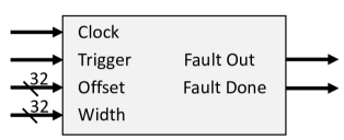
Figure 4 shows a block diagram of a typical SFU. Similar designs are commonly used to inject a single voltage fault into a Device under Test (DuT). A voltage fault is defined by its Width and its Offset, w.r.t. a synchronization point referred to as the Trigger (cf. subsection 2.1). In our SFU design, the Width and Offset are both defined as Bit inputs. A SFI is initiated, once the single bit Trigger input signal is asserted. Starting with this external Trigger event, the hardware starts counting, using the reference Clock signal. Once the defined Offset has been reached, the Fault Out signal is set high and remains high for exactly Width clock cycles. The Fault Out signal is routed directly into the gate of a N-Channel metal–oxide–semiconductor field-effect transistor (MOSFET), with its source connected to the fault voltage level and its drain connected to the power supply line of the DuT. This circuit is referred to as the Crowbar-Circuit [40] and represents the state-of-the-art method used to inject a voltage fault. To indicate that the fault attempt has been processed, an additional output signal named Fault Done is asserted for a single clock cycle.
5.3.1 Multiple Fault Injection Hardware
The SFU discussed previously builds the base for the design of our MFI unit. By chaining multiple SFUs together, we are able to inject multiple, coordinated faults using a single trigger. For this purpose, the Trigger input of a unit is connected to the Fault Done signal of its predecessor, whereas the first SFU’s Trigger is directly connected to the external Trigger signal, forming a chain of units. The Fault Out lines are combined by using the logical Or operator, whereas the signal indicating the termination of each MFI attempt is solely defined by the last SFU’s Fault Done signal. By chaining SFUs a single trigger signal can be used to perform MFI.
While this approach is capable of injecting multiple, coordinated faults into a DuT, the number of injected faults is fixed by design. Once there are SFUs downloaded to the Field Programmable Gate Array (FPGA), the framework is determined to generate exactly voltage faults, each time it gets triggered. With respect to our attack flow described in section 4, the dynamical configuration of the number of injected faults is desirable. Hence, we propose a slightly more complex design, which enables the dynamic activation and deactivation of SFUs, even after the hardware has been downloaded to the FPGA. By introducing multiplexers in between each of the SFUs, as shown in Figure 5, the design is dynamically configurable.
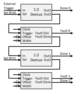
In this depiction, the routing of the Clock, Offset and Width signals of each SFU are intentionally omitted, in order to focus on the interconnection of multiple SFUs. In addition, all the Fault Out signals (Fault 0, Fault 1, …) are assumed to be combined using the logical Or operator. The hereby generated signal controls the gate of the MOSFET of our Crowbar circuit implementation. The blocks labeled 1:2 Demux are demultiplexers, i.e., hardware units which forward an input signal (In) to one of multiple output signals (Out1 or Out2), depending on the state of another input signal (Sel). The selection lines (Sel SFU0, Sel SFU1, …) may be modified by the controlling host system, by updating the MFI framework’s internal registers. The first demultiplexer, which routes its input to Out1 asserts one of the Done signals, which indicates the end of this MFI attempt and interrupts the forwarding of Done-Signals to succeeding SFUs. Each of the Fault Done signals (i.e. Done 0, Done 1, Done 2, …) are also combined using the logical Or operator, to form a single output signal.
6 Evaluation
To thoroughly test our -Glitch Multiple Fault Injection (MFI) hardware design and novel parameter search algorithm, we conduct multiple evaluations throughout this section. First, we show the feasibility of attacking the Duplicate Registers countermeasure, this method is mimicked and attacked based on a cooperative as well as a non-cooperative firmware simulation. By this our novel approach of searching for parameters can be compared to performing an exhaustive search, with optimized conventional parameter search algorithms. Moreover, in order to prevent the security context switch, we perform a privilege escalation on code generated by Gnu Compiler Collection (GCC). The Fault Target are two immediately successive instructions, which have both to be attacked at once. For this purpose we evaluate, whether it is more promising to inject two, narrow faults or a single, wider fault when aiming at attacking such successive instructions. We conclude our evaluation by performing our real-world attack, in which we attack NXP’s TrustZone-M (TZM) implementation with all the new protections activated, by hitting all Fault Targets introduced in subsubsection 5.2.3 in one execution.
6.1 Attacking Duplicate Registers
To show the feasibility of circumventing the Duplicate Register Fault Injection (FI) countermeasure and evaluate our proposed MFI parameter search algorithm we implement an isolated simulation of this countermeasure. It is possible without loss of generality, since the Duplicate Register method and our simulation both translate to equal Fault Targets. In the following we describe our simulation approach for cooperative as well as non-cooperative parameter searches. Afterwards, multiple parameter searches for both the different setups are performed. We conclude this simulation by analyzing the success rates for attacking our simulation of the Duplicate Registers FI countermeasure.
6.1.1 Fault Targets
In order to simulate the Duplicate Registers Fault Injection countermeasure, we first define two functions, which are used for the different MFI setups (i.e., cooperative and non-cooperative), and whose source code is provided as a reference in the Appendix in LABEL:lst:parameter_non_cooperative and LABEL:lst:cooperative_fault_target. In both functions two, zero initialized variables are defined. These represent our Fault Targets, i.e., a register to be protected and its duplicate register. After their definitions, these are written sequentially with the same, non-zero value. The goal of the adversary is to skip both the assignments in one execution, hence compromising the protection introduced by the Duplicate Registers method. In our cooperative simulation Partial Success Functions (PSFs) are defined, which allows the use of our efficient approach, as described in section 4. For comparison, in the non-cooperative simulation, PSFs are assumed to be impossible to define, and an optimized exhaustive search is performed. We chose to use the exhaustive search approach as proposed by NewAE, as it represents the state-of-the-art in Single Fault Injection (SFI) attacks888https://github.com/newaetech/chipwhisperer-jupyter/tree/92307484b155394a01c7021f1d21123efccee4aa/courses/fault101, which tests all possible combinations of FI parameters. This search requires no additional knowledge in contrast to other approaches which require time consuming model training [64] for every glitch or the definition of a fitness function [12], which may not always be possible. Each assignment to a Fault Target is preceded with a random delay, which is determined during compile-time. Through this, the binary firmware exhibits exactly the same behavior during each execution. Once the firmware is re-compiled, another binary is generated which exhibits a different timely behavior. This way we ensure that parameters discovered throughout one experiment are very unlikely to fit another experiment. In order to compare the different setups, the same delays for both setups have been used.
6.1.2 Parameter Search
The different search algorithms, used to discover MFI parameters, are performed several times based on the introduced random delays, before comparing the results of the different approaches to each other. Table 1 compares an exhaustive search (left) to our efficient sweeping approach (right). Each row represents a single comparison of an exhaustive search to our cooperative approach, based on the depicted compile-time delays. The results for applying our sweeping approach are divided into the time to search the parameters based on PSFs (left) and their integration (right). It shows that our novel approach in a MFI context is much more efficient than the traditional exhaustive search. Here, for every comparison our novel approach required approximately two percent of the time required by the exhaustive search.
| Delay 1 | Delay 2 | Exhaustive | Sweeping |
|---|---|---|---|
| 7 | 43 | 12:31h | 00:06h + 00:09h |
| 33 | 19 | 21:01h | 00:18h + 00:10h |
| 4 | 50 | 07:46h | 00:02h + 00:09h |
| 22 | 1 | 16:04h | 00:11h + 00:10h |
6.1.3 Evaluation And Repeatability
For each of the previous MFI parameter searches, multiple combinations of MFI parameters have been returned, which have shown to evaluate the Success Function (SF) to success. Moreover, both parameter search algorithms yielded similar fault parameters, which exhibit only negligible differences. When performing an actual attack, an adversary would always choose the combination of parameters, which has the highest probability for an attack to succeed. Therefore, each previously determined successful combination has to be qualified by means of their reliability and repeatability.
For this we first define the most promising attack parameters as the parameters, which show the highest success rate of our attack. To estimate the most promising parameters, we perform MFI times based on different successful parameter configurations. Once the most promising attack parameters have been determined, MFI attempts are performed. The experiment returned a success rate of and a respective failure rate of . This means, that by using our highly precise MFI design about every fifth attempt of injecting two consecutive faults into our Device under Test (DuT) in order to overcome the Duplicate Registers simulation succeeded.
6.2 Attacking Successive Instructions
As mentioned in subsubsection 5.2.3, besides skipping the activation of the Security Attribution Unit (SAU) and the activation of the Secure Advanced High-Performance Bus (AHB) Controller, an additional privilege escalation is required. The Fault Targets are two, directly succeeding shift instructions, which, under normal circumstances, unset the Least Significant Bit (LSB) of the NS target address.
With the following simulation, we aim to evaluate if immediately successive instructions, as they are encountered in this scenario, are best to be attacked by a single, wider fault or by multiple, narrow ones.
6.2.1 Fault Targets
Our Fault Targets are depicted in line 10 and 11 of our cooperative firmware example in LABEL:lst:succeeding_fault_targets. This simulation defines a variable labeled and assigns it an odd value of , i.e., the LSB is set. Based on the returned value, an adversary is able to distinguish which Fault Targets have been hit. If, e.g., only the left shift instruction has been skipped, then the returned value must be equal to . Under normal circumstances both shift operations are performed, clearing the LSB and resulting in a returned value of .
6.2.2 Parameter Search
Throughout this simulation, we assume that the most promising attack parameters are already known, computed by using our efficient search approach.
6.2.3 Evaluation And Repeatability
We evaluate performing both, a broad SFI as well as two narrow MFI on the previously introduced Fault Targets to demonstrate how MFI compares to SFI when attempting to attack instructions that immediately follow another. For this evaluation, FI attempts have been performed. Throughout this experiment we define the group of invalid results as these results, where the DuT is either not responding after performing MFI or which cannot be explained by either skipping of the shift instructions.
Using a single, wider fault in order to fault two successive shift instruction resulted in a success rate of , whereas attacking the same instructions using two, narrow faults resulted in a success rate of . Moreover, the group of invalid results increased by . Hence, with respect to the success rate it is more reasonable for an adversary to inject a single fault, utilizing an increased Width, in order to attack the two successive shift instructions. The complete results are shown in the Appendix in Table 4.
6.3 Attacking The TrustZone-M
In this part, we evaluate our novel approach by attacking NXP’s implementation of the TZM and all of the additional countermeasures in a real-world scenario. Throughout this experiment, the MFI framework’s frequency is specified as being times higher, than the frequency of the DuT. By oversampling of our MFI framework w.r.t. the DuT, we gain additional precision for each of our FI attempts. Note, that it is possible to increase the success rate by increasing the oversampling rate or synchronizing the glitch to the DuT’s clock signal[44]. This, unfortunately, would also mean to introduce more assumptions.
The firmware has been built based on the unmodified NXP’s Software Development Kit (SDK) TZM examples. The Fault Targets have been described in detail throughout subsubsection 5.2.3, as the activation of the SAU, the activation of the Secure AHB Controller, the duplicate register for the activation of Secure AHB Controller and performing privilege escalation.
After all these Fault Targets have been hit during a single, consecutive execution of the targets firmware, the NS code is able to arbitrarily access any S and NS resources. In the context of Trusted Execution Environments (TEEs), this represents a full compromise, as e.g., any secrets stored within secure memory may be disclosed and any secure defined peripheral may be arbitrary accessed and controlled from within non-secure code.
Moreover, up to this point all parts of our attack have already been proven feasible and practical, by attacking isolated simulations. We are presenting our results, in terms of repeatability and reliability of our attack, in comparison with the conventional exhaustive parameter search.
6.3.1 Search For Parameters
The search for parameters is evaluated for a cooperative setup as well as a non-cooperative setup, in which no PSFs can be defined. The results of comparing both parameter searches are depicted in Table 2.
| Brute Force Search Time |
|
||
|---|---|---|---|
| >24h | 06:17h + 00:28h | ||
| >24h | 08:07h + 00:28h | ||
| >24h | 13:22h + 00:30h | ||
| 23:40h | 02:58h + 00:28h |
Four different search passes for the same four Fault Targets have been performed with a limit of hours. While the exhaustive approach led in only one of four parameter searches to a result within the given time limit, our sweeping approach has returned correct parameters for every single attempt. Moreover, the fastest exhaustive search has shown to be eight times slower, than the corresponding sweeping approach. The results of the sweeping approach are again split into the time it took to search the single fault parameters (left) and the time it took to integrate the respective parameters (right). It is worth noting, that there is quite some variance contained in the depicted results, which can be explained by the non-deterministic behavior of FI, i.e., even if the parameters are perfectly set, the injected fault can never guarantee a success. Due to the non-deterministic discovery of fault parameters, we implemented our parameter searches to restart themselves, if either no total success has been observed for a non-cooperative setup, or not at least one partial success has been observed for every Fault Target, in a cooperative setup.
Note, that in this attack scenario it is possible to escalate a non-cooperative setup to a cooperative by using the parameter transfer described in subsection 4.1.
6.3.2 Evaluation and Repeatability
After conducting the MFI parameter searches, for each setup a set of sets of fault parameter configurations has been returned, based on which the SF evaluated to success. As the parameter found by both search algorithms differ only negligibly we used the parameters returned by our efficient, MFI parameter search, in order to determine the most promising attack parameters. After these parameters are estimated, these are used to perform MFI attempts, in order to compromise the TZM. Moreover, this evaluation has been performed two times. The averaged results of both experiments are depicted in Table 3.
| Fault Targets | Success Rate |
|---|---|
| SAU | |
| SAU & AHB CTRL | |
| SAU & AHB CTRL & DUPL | |
| SAU & AHB CTRL & DUPL & PE |
.
The success rates when injecting exactly one (only disabling the SAU) up to four (completely disabling TZM) faults based on the most promising attack parameters are depicted. SAU is referring to the first Fault Target, i.e., the activation of the SAU, AHB CTRL is referring to the activation of the Secure AHB Controller, DUPL is referring to the Duplicate Register of the Secure AHB Controller and PE is referring to the privilege escalation. These result indicate that almost every second attempt () to inject four faults into the DuT is deactivating the SAU. Moreover, of the performed FI attempts successfully disabled the Secure AHB Controller in addition. An average of of FI attempts succeeded in attacking the activation of the SAU, the activation of the Secure AHB Controller as well as the Duplicate Register of the Secure AHB Controller all at once. And finally, MFI attempts resulted in a total success. Conducting such high amounts of FI attempts may seem excessive at first, however, performing one million FI attempts took only one and a half days, translating to one successful attempt in half a day. With respect to the potential damage this practical attack may cause, once successful, we consider this attack critical.
6.3.3 -Glitch Transferability
We evaluated the end-to-end attack for disabling TZM, both on cooperative as well as non-cooperative Multiple Voltage Fault Injection (MVFI) setups, on different target Integrated Circuits (ICs), namely STMs STM32L5, Atmels SAML11 and NXPs LPC55S69 and RT6600 Microcontroller Units (MCUs). In the Appendix in Table 5 we show the attacked chips and the necessary Fault Targets to achieve disabling TZM per chip. In addition, we show the time for baseline exhaustive search (capped at 48h) in contrast to our sweeping approach and the combined success rate of all glitches combined. RT600 is conceptionally similar to the LPC55S69 and can be attacked using the same Fault Targets. SAML11 configuration is stored in Non-Volatile-Memory (NVM) space and either modifying read information or glitching the bootloader is necessary. In order to disable the Brownout Detection (BoD) of the STM32L5, which may interfere with Voltage Fault Injection (VFI), glitching of the Phase Locked Loop (PLL) configuration is necessary, in order to run the chip with a clock frequency of in case the chip is configured to run faster. According to our evaluation -Glitch can successfully attack conceptionally similar ICs.
7 Potential Countermeasure
Inspired by the insights of our evaluation we propose a potential countermeasure against Multiple Fault Injection (MFI) attacks. We propose an Information Level Countermeasures (ILC), as this kind of countermeasure may also be applied on already deployed hardware, i.e., no novel hardware revision is required in order to deploy physical sensors.
By attacking the Duplicate Registers method throughout this work, we have shown that single fault injection protections on the instruction level may be overcome by injecting additional faults. This is possible due to the fact that the Fault Targets are located at always the same offsets. Hence, an adversary is able to conduct a multiple parameter search and thus form a reliable attack.
Our concept of randomizing the Duplicate Registers makes use of random delays, in order to strengthen the Duplicate Register method against MFI attacks, by removing the possibility to search for MFI parameters. For this, we propose the use of a compiler pass, which introduces a compiler attribute that can be used to security critical assignments. As the random delay is only introduced when the aforementioned attribute is encountered, the overhead on the computation in general is negligible.
The goal is to generate machine instructions, which force the processor to stall for a small, random period of time. With this, a parameter search can not be successfully carried out as the Offset of the Fault Targets varies on a per-execution base. Hereby however, a trade-off is introduced between increasing the parameter search space by introducing a large delay and the minimization of overhead in processor time by using a small delay. When conducting our experiments, the MFI frameworks internal frequency has been chosen to be up to times higher, than that of the Device under Test (DuT). Here we have observed, that a timing difference of less than a single DuT’s clock cycle leads to no successes. Hence we assume that the stall time can be kept low without compromising the security.
As by this method there is no possibility to conduct a parameter search, the best possible attack is to inject, random parameterized faults into the DuT, which leads to impracticability of a MFI attack, by decreasing its success rate tremendously.
By utilizing this approach to attack two Fault Targets, which have a random preceding delay of 0-9 cycles, the probability of injecting two successful glitches is 100 times lower than without this protection.
8 Discussion
We argue -Glitch to be applicable to most Microcontroller Units (MCUs) with TrustZone-M (TZM), as the adversary only needs to have access to the power supply of the IC, no need to supply the DuT‘s clock signal by using oversampling and the TZM setup code of most MCUs is open source knowledge in form of Software Development Kits (SDKs).
Naturally, -Glitch is not limited to conduct attacks against TZM. Van den Herrewegen et al. [58] used Single Fault Injection (SFI) to deactivate debugging protections to exfiltrate data. In recent MCUs by NXP, the debug interfaces are protected by duplication based approaches, therefore, SFI attacks cannot be used anymore. Hence, in order to overcome the debug features protection, -Glitch Multiple Voltage Fault Injection (MVFI) approach becomes mandatory.
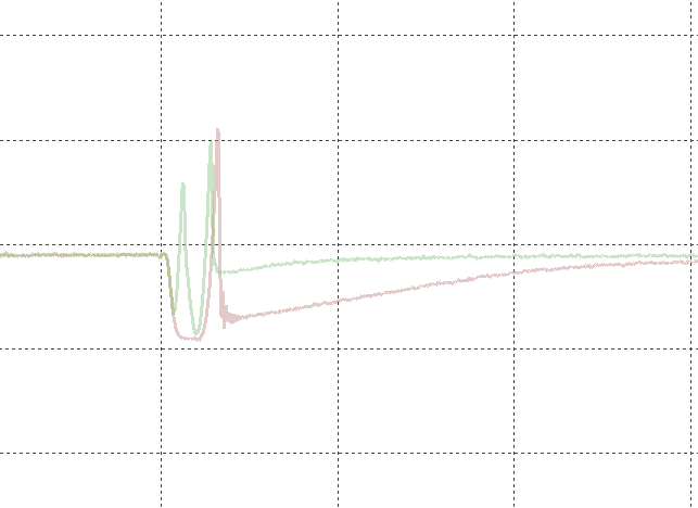
We also evaluated using -Glitch to overcome the mitigating effects of Brownout Detection (BoD) against Voltage Fault Injection (VFI). Even though it is indented to be a safety feature to power down an embedded device whenever the battery based voltage supply drops below a certain threshold, it has also been shown to detect the voltage drops caused by VFI. In sampling based BoD approaches the supply voltage is measured periodically, which is commonly encoutered in embedded devices, as it has a relatively low power consumption. If the BoD sampling frequency is high enough, it may happen that a voltage fault can be detected. We therefore propose to split a single, wider voltage fault into several, narrower ones exhibiting a similar effect on the target. Based on this, we were able to overcome a sampling based BoD by using two voltage faults, instead of a single fault which triggered the BOD. Unfortunately, the success rate of using two narrower glitches instead of one, is lower, as the chance to find a sweet-spot is decreasing which each additional glitch. Exemplary, the original and the first of the split glitches have the same offset. The width of the original glitch is . A double-fault inheriting a similar experiment outcome is represented by the two widths of and with an in-between offset of . A graphic depiction can be seen in the Appendix in Figure 6.
9 Related Work
In the following, we provide a summary of existing Fault Injection (FI) attacks, attacks on Trusted Execution Environments (TEEs) as well as FI countermeasures.
Fault Injection Attacks:
Several FI attacks have been proposed over the last years, which we utilize in this work. Our work builds on top of Roth [46], who has attacked several implementations of the TrustZone-M by injecting a single voltage fault. The author aimed at hitting Fault Targets, which set the lower bounds of NS regions, therefore extending the regions to ultimately accessing sensitive, secure data. For this purpose firmware examples were attacked, which did not activate the vendor specific backchecking mechanisms of TrustZone-M implementations. In contrast to this, we focus on providing a reliable and repeatable procedure of conducting Multiple Fault Injection (MFI) attacks, which is able to circumvent all protections which are enabled by default in NXP’s Software Development Kit (SDK). Trichina et al. [56] propose two-fault attacks on protected CRT-RSA implementations running on an advanced 32 bit ARM Cortex M3 core. The authors performed two-fault Laser Fault Injection (LFI) on a protected cryptographic application, as LFI exhibits a high spatial resolution. Nashimoto et al. [35] combined stack based Buffer Overflow (BO) attacks with two-fault Clock Fault Injection (CFI), in order to prevent the BO from being detected. Colin O’Flynn [40] showed that Voltage Fault Injection (VFI) may exhibit a high timely resolution based on his proposed Crowbar circuit, which we utilize in this work. We have shown that by using this circuitry it is further possible to inject multiple voltage faults within a short period of time. Bozzato et al. [9] replaced the Crowbar circuit by a Digital to Analog Converter (DAC). This way improving VFI by increasing transferability to other hardware, being able to attack Brownout Detection (BoD) enabled Integrated Circuits (ICs) and injecting faults based on arbitrary waveforms. While the authors mention to be able to inject multiple faults, they fell short of showing MFI attacks using their hardware and provided no evaluation, as they focus in their work on increasing the reliability and repeatability of Single Fault Injection (SFI). Timmers et al. [55] performed VFI in order to corrupt the instruction decoding stages of the internal processor pipeline, with the goal of hijacking the control flow by setting the Peripheral Checker (PC) to predefined addresses stored in general purpose registers. In a later work, Timmers et al. [54] showed that in an embedded Linux Operating System (OS) the privileges can be escalated from user to system privileges by performing VFI. By performing VFI against AMD’s Secure Processor (SP), Buhren et al. [11] where able to control the key management and by this, compromise the security of AMD’s Secure Encrypted Virtualization (SEV). An overview of fault attacks on embedded devices is provided by Yuce et al. [65]. Werner et al. [62] generate fault models for LFI based on fault injection simulations.
The first Multiple Clock Fault Injection (MCFI) has been demonstrated by Blömer et al. [8], attacking two consecutive instructions during a single execution by directly modifying the clock signal. For this attack to succeed the external clock signal has to be fed directly into the processing part of the Device under Test (DuT). However, as of today, most ICs use Phase Locked Loops (PLLs) which were shown to gracefully protect against clock glitching. Further, MFI has been performed by Colombier et al. [15] using a LFI setup. Due to its sophisticated spatial and timely resolution, optical fault injection forms a promising candidate for MFI. LFI setups, however are quite costly. A single LFI setup is commonly encountered in the magnitude of $100.000, whereas the cost for a multiple LFI setup is even higher. Moreover, in order to conduct LFI attacks, in general a much more invasive preprocessing of the DuT is required, in comparison to VFI. Electromagnetic Fault Injection is commonly not considered to be used in MFI setups, as the internal capacitor banks take too much time in order to be recharged, thus rapid successfully injected consecutive faults cannot be guaranteed.
Commercial equipment for MFI, e.g., Alphanov’s double laser fault injection microscope (D-LMS) and Riscure’s VC Glitcher are fairly expensive and only shown to conduct Multiple Laser Fault Injection (MLFI). Devices from NewAE [44] cannot conduct Multiple Voltage Fault Injection (MVFI) but need a separate trigger for every glitch to be injected.
In contrast, -Glitch, is capable of reliably performing MVFI based on low-cost hardware. We aim at attacking setups, in which commonly only a single, synchronizing trigger signal can be asserted. To the best of our knowledge, the possibility of conducting MVFI has not been studied before.
Cryptographic Attacks:
Differential Fault Analysis (DFA) has first been described by Biham and Shamir [7]. It poses a cryptanalytic attack which exploits computational errors in order to disclose cryptographic keys. In recent years publications attacking today’s Advanced Encryption Standard (AES) [18, 57, 51], Rivest-Shamir-Adleman-Cryptosystem (RSA) [2], Data Encryption Standard (DES) [64], recent cryptographic Hash Functions [27, 29] and many more [26, 6, 13, 20] emerged.
Trusted Execution Environment Attacks:
In recent years attacks utilizing different attack vectors against popular TEEs like ARM’sTrustZone (TZ) as well as Intel’s Software Guard Extension (SGX) were published.
Tang et al. [53] presented the CLKSCREW attack, which exploited an on-chip energy regulation mechanism in order to break the security promises by ARM’s TrustZone. Kenjar et al. [23] described another software controlled, but hardware based fault injection approach, in which the authors were able to compromise any operating mode of Intel processors by modifying the frequency and voltage through privileged software interfaces. The authors showed that software management interfaces can be exploited to undermine the system’s security. Qui et al. [45] performed a software based voltage fault injection, by abusing the Dynamic Voltage and Frequency Scaling (DVFS) techniques for energy efficiency, allowing them to attack a secure software implementation of AES. Ryan [47] showed, that ARM’s TZ is susceptible to cache based attacks, which exhibit high temporal precision, high spatial precision and low noise. The author was able to fully recover a 256-bit private key from Qualcomm’s version of the hardware-backed keystore. Ning et al. [37] exploited security vulnerabilities in ARMs software debugging features to extract sensitive information from TZ. Jang et al. [21] performed a denial-of-service against SGX, in which the CPU could be shutdown by performing a Rowhammer [34] attack. Lee et al. [25] found that it is indeed possible to circumvent the hardware protections provided by the SGX design by performing Return Oriented Programming (ROP) attacks.
Different attack vectors were used in the past to attack TEEs, including TZ, however these attack vectors are not suitable for MVFI and therefore not able to overcome SFI based protection mechanisms such as utilized by LPC55SXX and RT6XX Microcontroller Units (MCUs).
Fault Injection Countermeasures:
Due to the vast amount of proposed work in this field, we present an overview in the Appendix in Table 6, where we list several proposed FI countermeasures, which are further classified into Information Level Countermeasuress (ILCs) [38, 39, 4, 48, 32, 5] and Hardware Level Countermeasuress (HLCs) [30, 19, 10, 17, 31, 22, 61, 50]. Due to the higher abstraction of ILCs, these protect against a certain Fault Model, whereas the HLCs are generally deployed to protect against a certain type of FI. The last column determines, whether or not this countermeasure is theoretically able to protect from voltage MFI attacks, as described throughout our work. A check (✓) indicates, that the respective countermeasure is able to protect from multiple voltage fault injection, whereas a cross (×) indicates, that it is not. Regarding the ILCs, these must be directed against Instruction Skipping in order to protect from our proposed MFI attack, whereas the HLCs must be deployed in order to detect VFI.
Moro et al. [32] proposed a duplication based ILC replacement approach for most Thumb-2 instructions. Moreover, Barry et al. [5] proposed a follow-up ILC, as not every instruction could be automatically replaced by the modified Low Level Virtual Machine (LLVM) based compiler and hence, required manual analysis. The authors base their countermeasures on the assumption that attacking successive instructions using FI is hard. We showed in subsection 6.2 that, in principal, -Glitch is able to attack successive instructions. Therefore, we denote this with a checkmark in parenthesis in Table 6.
Vosoughi et al. [61] propose a HLC which is able to mitigate the effect of VFI on the IC. Naturally, it can also protect against MFI using VFI, but it depends on specific on-chip voltage regulators to be present in the IC, which is not present at all times. Similarly, Singh et al. [50] propose an application specific HLC, which has to be adapted to the specific application to be protected.
10 Conclusion
In this paper, we introduced a novel multiple voltage fault injection platform, coined -Glitch, which is capable of injecting multiple, coordinated voltage faults into arbitrary target devices, in order to attack multiple fault targets during a single execution of the target’s firmware. We proposed and evaluated a novel, efficient parameter search algorithm for multiple voltage fault injection attacks. By the hereby introduced attack vector, a novel threat model emerges, in which the adversary is capable of defeating most instruction level countermeasures, as they are mostly implemented to protect from single fault injection attacks. We have shown, that by using our novel approach a TrustZone-M implementation can be attacked, in which there are multiple, inter-dependent fault targets to overcome, including a specific fault injection protection. Finally, we have discussed possible countermeasures to thwart multiple fault injection attacks.
References
- [1] Atmel. SAM L10/L11 Family Datasheet, 2019.
- [2] Christian Aumüller, Peter Bier, Wieland Fischer, Peter Hofreiter, and J-P Seifert. Fault attacks on rsa with crt: Concrete results and practical countermeasures. In International Workshop on Cryptographic Hardware and Embedded Systems. Springer, 2002.
- [3] Alessandro Barenghi, Guido Bertoni, Emanuele Parrinello, and Gerardo Pelosi. Low voltage fault attacks on the rsa cryptosystem. In 2009 Workshop on Fault Diagnosis and Tolerance in Cryptography (FDTC), 2009.
- [4] Alessandro Barenghi, Luca Breveglieri, Israel Koren, Gerardo Pelosi, and Francesco Regazzoni. Countermeasures against fault attacks on software implemented aes: Effectiveness and cost. In Proceedings of the 5th Workshop on Embedded Systems Security, WESS ’10. Association for Computing Machinery, 2010.
- [5] Thierno Barry, Damien Couroussé, and Bruno Robisson. Compilation of a countermeasure against instruction-skip fault attacks. In Proceedings of the Third Workshop on Cryptography and Security in Computing Systems, CS2 ’16. Association for Computing Machinery, 2016.
- [6] Eli Biham, Louis Granboulan, and Phong Q. Nguyen. Impossible fault analysis of rc4 and differential fault analysis of rc4. In Henri Gilbert and Helena Handschuh, editors, Fast Software Encryption. Springer Berlin Heidelberg, 2005.
- [7] Eli Biham and Adi Shamir. Differential fault analysis of secret key cryptosystems. In Burton S. Kaliski, editor, Advances in Cryptology — CRYPTO ’97. Springer Berlin Heidelberg, 1997.
- [8] Johannes Blömer, Ricardo Gomes da Silva, Peter Günther, Juliane Krämer, and Jean-Pierre Seifert. A practical second-order fault attack against a real-world pairing implementation. In 2014 Workshop on Fault Diagnosis and Tolerance in Cryptography, 2014.
- [9] Claudio Bozzato, Riccardo Focardi, and Francesco Palmarini. Shaping the glitch: Optimizing voltage fault injection attacks. IACR Transactions on Cryptographic Hardware and Embedded Systems, 2019(2), 2019.
- [10] Jakub Breier, Shivam Bhasin, and Wei He. An electromagnetic fault injection sensor using hogge phase-detector. In 2017 18th International Symposium on Quality Electronic Design (ISQED), 2017.
- [11] Robert Buhren, Hans-Niklas Jacob, Thilo Krachenfels, and Jean-Pierre Seifert. One glitch to rule them all: Fault injection attacks against amd’s secure encrypted virtualization. In Proceedings of the 2021 ACM SIGSAC Conference on Computer and Communications Security, CCS ’21. Association for Computing Machinery, 2021.
- [12] Rafael Boix Carpi, Stjepan Picek, Lejla Batina, Federico Menarini, Domagoj Jakobovic, and Marin Golub. Glitch it if you can: Parameter search strategies for successful fault injection. In Aurélien Francillon and Pankaj Rohatgi, editors, Smart Card Research and Advanced Applications. Springer International Publishing, 2014.
- [13] Hua Chen, Wenling Wu, and Dengguo Feng. Differential fault analysis on clefia. In Sihan Qing, Hideki Imai, and Guilin Wang, editors, Information and Communications Security. Springer Berlin Heidelberg, 2007.
- [14] Zitai Chen, Georgios Vasilakis, Kit Murdock, Edward Dean, David Oswald, and Flavio D. Garcia. Voltpillager: Hardware-based fault injection attacks against intel SGX enclaves using the SVID voltage scaling interface. In USENIX Security. USENIX Association, 2021.
- [15] Brice Colombier, Paul Grandamme, Julien Vernay, Émilie Chanavat, Lilian Bossuet, Lucie de Laulanié, and Bruno Chassagne. Multi-spot laser fault injection setup: New possibilities for fault injection attacks. In Vincent Grosso and Thomas Pöppelmann, editors, Smart Card Research and Advanced Applications. Springer International Publishing, 2022.
- [16] Ang Cui and Rick Housley. BADFET: Defeating modern secure boot using second-order pulsed electromagnetic fault injection. In 11th USENIX Workshop on Offensive Technologies (WOOT 17). USENIX Association, 2017.
- [17] Chinmay Deshpande, Bilgiday Yuce, Leyla Nazhandali, and Patrick Schaumont. Employing dual-complementary flip-flops to detect emfi attacks. In 2017 Asian Hardware Oriented Security and Trust Symposium (AsianHOST), 2017.
- [18] Pierre Dusart, Gilles Letourneux, and Olivier Vivolo. Differential fault analysis on a.e.s. In Jianying Zhou, Moti Yung, and Yongfei Han, editors, Applied Cryptography and Network Security. Springer Berlin Heidelberg, 2003.
- [19] Wei He, Jakub Breier, Shivam Bhasin, Noriyuki Miura, and Makoto Nagata. An fpga-compatible pll-based sensor against fault injection attack. In 2017 22nd Asia and South Pacific Design Automation Conference (ASP-DAC), 2017.
- [20] Michal Hojsík and Bohuslav Rudolf. Differential fault analysis of trivium. In Kaisa Nyberg, editor, Fast Software Encryption. Springer Berlin Heidelberg, 2008.
- [21] Yeongjin Jang, Jaehyuk Lee, Sangho Lee, and Taesoo Kim. Sgx-bomb: Locking down the processor via rowhammer attack. In Proceedings of the 2nd Workshop on System Software for Trusted Execution, SysTEX’17. Association for Computing Machinery, 2017.
- [22] Raúl Jiménez-Naharro, Fernando Gómez-Bravo, Jonathan Medina-García, Manuel Sánchez-Raya, and Juan Antonio Gómez-Galán. A smart sensor for defending against clock glitching attacks on the I2C protocol in robotic applications. Sensors (Basel), 17(4), 2017.
- [23] Zijo Kenjar, Tommaso Frassetto, David Gens, Michael Franz, and Ahmad-Reza Sadeghi. V0LTpwn: Attacking x86 processor integrity from software. In 29th USENIX Security Symposium (USENIX Security 20). USENIX Association, 2020.
- [24] Christian Kudera, Markus Kammerstetter, Markus Müllner, Daniel Burian, and Wolfgang Kastner. Design and implementation of a negative voltage fault injection attack prototype. In 2018 IEEE International Workshop on Physical Attacks and Inspection of Electronics (PAINE), 2018.
- [25] Jaehyuk Lee, Jinsoo Jang, Yeongjin Jang, Nohyun Kwak, Yeseul Choi, Changho Choi, Taesoo Kim, Marcus Peinado, and Brent ByungHoon Kang. Hacking in darkness: Return-oriented programming against secure enclaves. In 26th USENIX Security Symposium (USENIX Security 17). USENIX Association, 2017.
- [26] Wei Li, Dawu Gu, and Juanru Li. Differential fault analysis on the aria algorithm. Information Sciences, 178(19), 2008.
- [27] Pei Luo, Yunsi Fei, Liwei Zhang, and A. Adam Ding. Differential fault analysis of sha3-224 and sha3-256. In 2016 Workshop on Fault Diagnosis and Tolerance in Cryptography (FDTC), 2016.
- [28] P. Maistri, R. Leveugle, L. Bossuet, A. Aubert, V. Fischer, B. Robisson, N. Moro, P. Maurine, J.-M. Dutertre, and M. Lisart. Electromagnetic analysis and fault injection onto secure circuits. In 2014 22nd International Conference on Very Large Scale Integration (VLSI-SoC), 2014.
- [29] Antun Maldini, Niels Samwel, Stjepan Picek, and Lejla Batina. Genetic algorithm-based electromagnetic fault injection. In 2018 Workshop on Fault Diagnosis and Tolerance in Cryptography (FDTC). IEEE, 2018.
- [30] Kohei Matsuda, Sho Tada, Makoto Nagata, Yuichi Komano, Yang Li, Takeshi Sugawara, Mitsugu Iwamoto, Kazuo Ohta, Kazuo Sakiyama, and Noriyuki Miura. An ic-level countermeasure against laser fault injection attack by information leakage sensing based on laser-induced opto-electric bulk current density. Japanese Journal of Applied Physics, 59(SG), 2020.
- [31] Noriyuki Miura, Zakaria Najm, Wei He, Shivam Bhasin, Xuan Thuy Ngo, Makoto Nagata, and Jean-Luc Danger. Pll to the rescue: a novel em fault countermeasure. In 2016 53nd ACM/EDAC/IEEE Design Automation Conference (DAC). IEEE, 2016.
- [32] N. Moro, K. Heydemann, E. Encrenaz, and B. Robisson. Formal verification of a software countermeasure against instruction skip attacks. Journal of Cryptographic Engineering, 4(3), 2014.
- [33] Nicolas Moro, Amine Dehbaoui, Karine Heydemann, Bruno Robisson, and Emmanuelle Encrenaz. Electromagnetic fault injection: Towards a fault model on a 32-bit microcontroller. In 2013 Workshop on Fault Diagnosis and Tolerance in Cryptography, 2013.
- [34] Onur Mutlu and Jeremie S. Kim. Rowhammer: A retrospective. IEEE Transactions on Computer-Aided Design of Integrated Circuits and Systems, 39(8), 2020.
- [35] Shoei Nashimoto, Naofumi Homma, Yu-ichi Hayashi, Junko Takahashi, Hitoshi Fuji, and Takafumi Aoki. Buffer overflow attack with multiple fault injection and a proven countermeasure. Journal of Cryptographic Engineering, 7(1), 2017.
- [36] Shoei Nashimoto, Daisuke Suzuki, Rei Ueno, and Naofumi Homma. Bypassing isolated execution on risc-v using side-channel-assisted fault-injection and its countermeasure. IACR Transactions on Cryptographic Hardware and Embedded Systems, 2022(1), 2021.
- [37] Zhenyu Ning and Fengwei Zhang. Understanding the security of arm debugging features. In 2019 IEEE Symposium on Security and Privacy (SP), pages 602–619. IEEE, 2019.
- [38] NXP. LPC55S6x/LPC55S2x/LPC552x User manual, 2021. Rev. 2.3.
- [39] NXP. UM11147, 2021. Rev. 1.4.
- [40] Colin O’Flynn. Fault injection using crowbars on embedded systems. IACR Cryptol. ePrint Arch., 2016, 2016.
- [41] Colin O’Flynn. Min()imum failure: EMFI attacks against USB stacks. In USENIX Workshop on Offensive Technologies (WOOT). USENIX Association, 2019.
- [42] Colin O’Flynn. Bam bam!! on reliability of emfi for in-situ automotive ecu attacks. Cryptology ePrint Archive, Report 2020/937, 2020.
- [43] Colin O’Flynn. Emfi for safety-critical testing of automotive systems. Cryptology ePrint Archive, Report 2021/1217, 2021.
- [44] Colin O’Flynn and Zhizhang David Chen. Chipwhisperer: An open-source platform for hardware embedded security research. In International Workshop on Constructive Side-Channel Analysis and Secure Design, pages 243–260. Springer, 2014.
- [45] Pengfei Qui, Dongsheng Wang, Yongqiang Lyu, and Gang Qu. Voltjockey: Abusing the processor voltage to break arm trustzone. GetMobile: Mobile Comp. and Comm., 24(2), 2020.
- [46] Thomas Roth. TrustZone-M(eh): Breaking ARMv8-M’s security. CCC, 2019.
- [47] Keegan Ryan. Hardware-backed heist: Extracting ecdsa keys from qualcomm’s trustzone. In Proceedings of the 2019 ACM SIGSAC Conference on Computer and Communications Security, CCS ’19. Association for Computing Machinery, 2019.
- [48] Junichi Sakamoto, Shungo Hayashi, Daisuke Fujimoto, and Tsutomu Matsumoto. Constructing software countermeasures against instruction manipulation attacks: an approach based on vulnerability evaluation using fault simulator. Cluster Computing, 2021.
- [49] Bodo Selmke, Florian Hauschild, and Johannes Obermaier. Peak clock: Fault injection into pll-based systems via clock manipulation. In Proceedings of the 3rd ACM Workshop on Attacks and Solutions in Hardware Security Workshop, ASHES’19. Association for Computing Machinery, 2019.
- [50] Arvind Singh, Monodeep Kar, Nikhil Chawla, and Saibal Mukhopadhyay. Mitigating power supply glitch based fault attacks with fast all-digital clock modulation circuit. In 2019 Design, Automation & Test in Europe Conference & Exhibition (DATE), 2019.
- [51] Hadi Soleimany, Nasour Bagheri, Hosein Hadipour, Prasanna Ravi, Shivam Bhasin, and Sara Mansouri. Practical multiple persistent faults analysis. Cryptology ePrint Archive, 2021.
- [52] STM. Arm TrustZone features for STM32L5 and STM32U5 Series, 2021. Rev. 5.
- [53] Adrian Tang, Simha Sethumadhavan, and Salvatore Stolfo. CLKSCREW: Exposing the perils of Security-Oblivious energy management. In 26th USENIX Security Symposium (USENIX Security 17), pages 1057–1074, Vancouver, BC, August 2017. USENIX Association.
- [54] Niek Timmers and Cristofaro Mune. Escalating privileges in linux using voltage fault injection. In 2017 Workshop on Fault Diagnosis and Tolerance in Cryptography (FDTC), 2017.
- [55] Niek Timmers, Albert Spruyt, and Marc Witteman. Controlling pc on arm using fault injection. In 2016 Workshop on Fault Diagnosis and Tolerance in Cryptography (FDTC), 2016.
- [56] Elena Trichina and Roman Korkikyan. Multi fault laser attacks on protected crt-rsa. In 2010 Workshop on Fault Diagnosis and Tolerance in Cryptography, 2010.
- [57] Michael Tunstall, Debdeep Mukhopadhyay, and Subidh Ali. Differential fault analysis of the advanced encryption standard using a single fault. In Claudio A. Ardagna and Jianying Zhou, editors, Information Security Theory and Practice. Security and Privacy of Mobile Devices in Wireless Communication. Springer Berlin Heidelberg, 2011.
- [58] Jan Van den Herrewegen, David Oswald, Flavio D Garcia, and Qais Temeiza. Fill your boots: Enhanced embedded bootloader exploits via fault injection and binary analysis. IACR Transactions on Cryptographic Hardware and Embedded Systems, pages 56–81, 2021.
- [59] Jasper G.J. van Woudenberg, Marc F. Witteman, and Federico Menarini. Practical optical fault injection on secure microcontrollers. In 2011 Workshop on Fault Diagnosis and Tolerance in Cryptography, 2011.
- [60] Sebastian Vasile, David Oswald, and Tom Chothia. Breaking all the things—a systematic survey of firmware extraction techniques for iot devices. In Begül Bilgin and Jean-Bernard Fischer, editors, Smart Card Research and Advanced Applications. Springer International Publishing, 2019.
- [61] Ali Vosoughi and Selçuk Köse. Leveraging on-chip voltage regulators against fault injection attacks. In Proceedings of the 2019 on Great Lakes Symposium on VLSI, GLSVLSI ’19. Association for Computing Machinery, 2019.
- [62] Vincent Werner, Laurent Maingault, and Marie-Laure Potet. An end-to-end approach for multi-fault attack vulnerability assessment. In 2020 Workshop on Fault Detection and Tolerance in Cryptography (FDTC), 2020.
- [63] Nils Wiersma and Ramiro Pareja. Safety != security: On the resilience of asil-d certified microcontrollers against fault injection attacks. In 2017 Workshop on Fault Diagnosis and Tolerance in Cryptography (FDTC), 2017.
- [64] Lichao Wu, Gerard Ribera, Noemie Beringuier-Boher, and Stjepan Picek. A fast characterization method for semi-invasive fault injection attacks. In Cryptographers’ Track at the RSA Conference. Springer, 2020.
- [65] Bilgiday Yuce, Patrick Schaumont, and Marc Witteman. Fault attacks on secure embedded software: Threats, design, and evaluation. Journal of Hardware and Systems Security, 2(2), 2018.
11 Appendix
11.1 Simulation 1
11.2 Simulation 2
11.3 Attacking Successive Instructions
| #Faults | Result Distribution | Invalid | |||
|---|---|---|---|---|---|
| None (a=0x12) | Only LSLS (a=0x9) | Only LSRS (a=0x38) | Both (a=0x13) | ||
| Single wide fault | 0.31 | 0.09 | 0.17 | 0.24 | 0.19 |
| Two narrow faults | 0.17 | 0.19 | 0.21 | 0.15 | 0.28 |
11.4 Evading Brown-out-Detection
11.5 Transferability
| Chip | FT1 | FT2 | FT3 | FT4 |
|
|
Successrate | ||||
|---|---|---|---|---|---|---|---|---|---|---|---|
| LPC55SXX | SAU | Secure AHB CTRL | DR | BXNS | >48h | 8.15h | 0.0000003 | ||||
| RT6XX | SAU | Secure AHB CTRL | DR | BXNS | >48h | 8.34h | 0.0000002 | ||||
| SAML11 | SAU | Bootloader* | - | BXNS | >48h | 4h | 0.0002566 | ||||
| STM32L5 | SAU | Gobal TZ Configuration | - | BXNS | >48h | 47h | 0.0034000 |
11.6 Countermeasures
| Reference | ILC | HLC | Fault Model / FI Method | Protects against VMFI |
| Duplicate Registers [38, 39] | × | Instruction Skipping | × | |
| Barenghi et al. [4] | × | Instruction Skipping | × | |
| Sakamoto et al. [48] | × | Instruction Manipulation | × | |
| Moro et al. [32] | × | Instruction Skipping | (✓) | |
| Barry et al. [5] | × | Instruction Skipping | (✓) | |
| Matsuda et al. [30] | × | Laser Fault Injection (LFI) | × | |
| Wei et al. [19] | × | LFI | × | |
| Breier et al. [10] | × | Electromagnetic Fault Injection (EMFI) | × | |
| Deshpande et al. [17] | × | EMFI | × | |
| Miura et al. [31] | × | EMFI | × | |
| Jimenez-Naharro et al. [22] | × | Clock Fault Injection (CFI) | × | |
| Vosoughi et al. [61] | × | Voltage Fault Injection (VFI) | ✓ | |
| Singh et al. [50] | × | VFI | ✓* |