Dynamical control of topology in ferroelectric skyrmions
via twisted light
Abstract
Twisted light carries a non-zero orbital angular momentum, that can be transferred from light to electrons and particles ranging from nanometers to micrometers. Up to now, the interplay between twisted light with dipolar systems has scarcely been explored, though the latter bear abundant forms of topologies such as skyrmions and embrace strong light-matter coupling. Here, using first-principles-based simulations, we show that twisted light can excite and drive dynamical polar skyrmions and transfer its nonzero winding number to ferroelectric ultrathin films. The skyrmion is successively created and annihilated alternately at the two interfaces, and experiences a periodic transition from a markedly “Bloch” to “Néel” character, accompanied with the emergence of a “Bloch point” topological defect with vanishing polarization. The dynamical evolution of skyrmions is connected to a constant jump of topological number between “0” and “1” over time. These intriguing phenomena are found to have an electrostatic origin. Our study thus demonstrates that, and explains why, this unique light-matter interaction can be very powerful in creating and manipulating topological solitons in functional materials.
With their noncolinear spin patterns and particle-like features [1, 2], skyrmions have attracted enormous interests in condensed matter physics. Their unique properties, such as topological hall effect [3, 4] and low current-driven motion [5, 6], enable promising applications, including racetrack memory and logic gates [7, 8, 9, 10]. Inspired by these discoveries, scientists recently aimed to seek an electric counterpart of topological solitons in ferroelectric systems, as they can be more easily controlled by electric field [11, 12, 13]. Polar patterns with skyrmion topologies have been predicted in BaTiO3/SrTiO3 nanocomposites and bulk PbTiO3 by first-principles-based approaches [14, 15], and lately skyrmion-like polar solitons have been observed in (PbTiO3)n/(SrTiO3)n superlattices and SrTiO3/Pb(ZrxTi1-x)O3/SrTiO3 heterostructures [16, 17, 18]. Different from magnetic skyrmions forming out of asymmetric exchange interaction between spins [19, 20], nontrivial ferroelectric structures typically originate from a competition between elastic, electrostatic and gradient energies [14, 21].
Moreover, the field of twisted light has rapidly developed over the last thirty years in multiple respects [22, 23, 24]. One type of twisted light, optical vortex (OV) beams, With features akin to superfluid vortices, carry a non-zero orbital angular momentum (OAM) with a phase singularity circulated by helical wavefront. Previous works show that the nontrivial field patterns can be imprinted in the generated photocurrent or motions of particles [25, 26, 27, 28, 29, 30], and nonuniform heating and magnetic field in the form of a vortex beam have been predicted to induce topological defects in chiral magnets [31, 32]. Thus it is timely and legitimate to wonder if the topological phase singularity in an optical field carrying OAM can be printed on dipoles to create topological solitons in ferroelectric systems.
Here, we indeed demonstrate that the OV beam can induce dynamical polar skyrmions at interfacial layers in ferroelectric Pb(ZrxTi1-x)O3 (PZT) ultrathin films, and allow such topological defects to move in a controllable manner. By interaction between this nontrivial light and electric dipoles, the in-plane electric field can induce a dynamical polar skyrmion with an unusual out-of-plane-dipole-component-switching. A topological defect “Bloch point” with vanishing polarization is identified for the first time in ferroelectrics and is involved in skyrmion creation [33, 34]. Moreover, the robustness of the mechanism manifests itself in the sense that the skyrmion is well maintained under different conditions, and its intrinsic characteristics such as size and switching speed are highly tunable by controlling external variables of the beam.
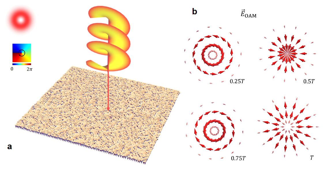
Technically, we use a first-principles-based effective Hamiltonian approach to study ferroelectric ultrathin films made of Pb(Zr0.4Ti0.6)O3 (PZT) [35, 36, 37]. Under different mechanical and electrical conditions, PZT and related systems have been found to exhibit several exotic phases, including vortex [38], flux-closure [39], and nanobubble domains [40]. Here, we introduce the lowest order of the “Laguerre-Gaussian” beam (i.e., = 0) propagating along the direction normal to the film and passing through the center of each (001) layer to interact with the well-equilibrated monodomain at 10 K (Fig. 1) [22]. As such, the time-dependent, in-plane electric field can be written as:
| (1) |
Here, and are polarization vectors along the - and -axes that are lying along the [100] and [010] pseudo-cubic (p.c.) directions, respectively; and characterize the phase twist of the field and the handness of the polarization, corresponding to orbital and spin angular momentum, respectively; , and denote the field magnitude, light frequency and beam radius, respectively. (, , ) is the position vector from the center of the supercell to any B-site of the film in cylindrical coordinates. In the present work, we set THz, = 5 unit cells (u.c.), and we consider for simplicity; as such, this electric field always has an in-plane orientation and carries a winding number [41]. Computational details about other parameters and justifications for choosing their values are detailed in the Supplementary Material.
Molecular dynamics simulations show that at the time ps, the local dipoles already establish a well defined cyclical motion passing through a sequence of states shown in Fig. 2a-b. Each of such states has a continuous rotational symmetry around the central line of the vortex beam. Hence, in the subpanels of Fig. 2a we show the distribution of dipoles only in one of the radial cross sections, i.e. the plane passing through the rotational symmetry axis. Technically, the slab used to model our PZT films have eight (001) layers, including one for the substrate (layer 1), five for the film (layers 2-6), and two for the vacuum (layers 7 and 8). Additionally, we schematically show in Fig. 2a1, b1 the structural evolution of the dipoles in the top and bottom planes of the film (further plots showing the time evolution of dipole configurations at these two planes are reported in Fig. S2).

At ps (Fig. 2a) the polar structure is homogeneous throughout all layers. The dipoles both at the center of the beam () and in the far-field region ( u.c.) retain their original downward orientation. In contrast, at the intermediate distances from the central line ( u.c.), the out-of-plane component () of electric dipoles is suppressed. Within this ring-shaped region, the in-plane components and grow following the intensity profile of the beam (Fig. 1a) and form an anti-clockwise vortex pattern (see the field configuration in Fig. 1b). The rotations from the out-of-plane to in-plane orientations have a pronounced Bloch character as illustrated in the top leftmost panel of Fig. 2a. Overall, the structure at ps can be described as an anti-clockwise annular vortex with downwards polarized core and surrounded by a downwards polarized matrix.
As time passes, the downwards polarized core () rapidly undergoes a partial switching. For instance, at ps the direction of the central dipole in top plane () is already reversed to . At the same time, the core dipoles in all other planes are still oriented downwards but their magnitude decreases with increasing . Such inhomogeneous core structure persists from ps up to ps, i.e. during almost a full half period. It is also important to note that owing to the gradient of at , the magnitude of the central dipole in the plane almost vanishes at ps and ps. As will be discussed later, such quasi-singular behavior as well as the reversal of at the top layer are non-trivial topological features. Note, however, that all layers possess similar patterns for the in-plane dipole components and at any given time (see Fig. S1).
Another structural change that occurs during the first half-period is the rotation of the dipoles around the axis (top row in Fig. 2a) which is remindful of the evolution of the OAM field (Fig. 1b). Such rotation gradually transforms the dominant Bloch component at ps into its center-convergent Néel counterpart at ps until, having accomplished a turn, the dipolar structure re-gains its assertive Bloch character at ps, but is reversed with respect to ps (rightmost vs leftmost top panel in Fig. 2a).
Thereby, the first half-period ends at ps with an annular vortex state akin to the ps structure but in a clock-wise manner. During the second half-period ps (Fig. 2b), dipoles at each site continue to rotate anti-clockwise around the axis. Such rotations generate the center-divergent (e.g. ps) and the anti-clockwise (e.g. ps) vortex patterns in the (,) planes. The corresponding mutual transformation of Bloch and Néel rotations are schematically shown in the top row of Fig. 2b. Moreover, similar to the first-half-period evolution, the core polarization is partially switched during ps. Yet, the reversal of is rather observed in the bottom () plane of the film, while in all other planes the magnitude of increases with . Consequently, the quasi-singular point () occurs in the plane.
One can readily notice (Figs. 2a1, b1) that the optical vortex creates polar skyrmion textures at the top and bottom interfaces of the film whenever the direction of the central dipole in the corresponding layers is reversed. This observation is confirmed by the calculated evolution of the skyrmion number for planes (Fig. 3a). As the in-plane dipole components closely follow the morphology of the OAM field, the skyrmion helicity also continuously evolves with time accompanying the vortex beam’s phase, i.e. [1]. For instance, a perfectly center-divergent (convergent) Néel skyrmion characterized by () forms at () on the bottom (top) interface; in contrast, at the same time, center-divergent(convergent) skyrmions never occur at the top (bottom) plane (Fig. 2a1, b1). Additionally, at or (), the system always opts for a topologically trivial annular vortex state instead of Bloch skyrmions. Since the dipoles forming the skyrmion texture have to cover the full body angle, such behavior is topologically tied to the inhomogeneous switching of at the center line.
Interestingly, such switching is not a direct effect of the beam-generated field since lacks an out-of-plane component at all times, but also vanishes at . Instead, the switching mechanism roots in the electrostatic interactions between and . Namely, the development of the radial component of polarization leads to a build-up of an electric bound charge . In response, by adopting a monotonically changing , the material develops a bound charge to compensate (illustrated in Fig. 3b). Such mechanism is further confirmed by our calculations of bound charges and evolving with time (see Supplementary Material). Thereby, depending on the sign and magnitude of , the reversal of occurs either in the vicinity of the top or bottom interfaces whenever , where denotes the film thickness. This condition also defines the critical values of parameters (e.g. field magnitude and film thickness ) required to create polar skyrmion textures by the OAM light (see Supplementary Material).
The evolution of and with time also allows to explain the formation of polar skyrmions from a topological perspective. Specifically, the continuity of polarization does not allow to vary with time, unless a topological transition occurs. This can be realized by introducing a Bloch point, a three-dimensional singularity with vanishing polarization. Such defect has been seen to mediate the dynamical evolution of magnetic skyrmions [42]. As being composed of planes with different , Bloch point can induce a jump of by 1 when going through these planes. Above discussion about Fig. 2 points out a negligible dipole moment at the center of layer 3 or layer 5 when skyrmion is present. Indeed, with the same method used in Ref. [34], by computing the topological charge of each cell, we find a negatively charged (-1) Bloch point at the center between layer 2 and layer 3 during 3.9–4.2 ps, and a positively charged (+1) Bloch point at the center between layer 5 and layer 6 during 3.4–3.7 ps, in concert with the presence of a skyrmion. According to Fig. 2, both Bloch points have spiraling configurations evolving with time as schematically shown in Fig. 3c, and they are involved in the creation of polar skyrmions.
We note of the two interfacial layers stay on “0” and “1” alternately. This behavior keeps proceeding as long as the OAM field does not vanish (Fig. S7). The interconversion between of “0” or “1” highly resembles digital binary signals and suggests that this dynamical skyrmion can be implemented as a component in logic gates. Though cannot be directly observed, it is associated with the switching of out-of-plane dipole components. This can be probed by measuring the out-of-plane polarization using interdigited electrodes [12]. Figure. 3d shows how averaged within the beam focus at each (001) layer changes with time. With periodic evolution of dipole components, we see that when the corresponding Néel-type skyrmion is formed, at layer 2 or layer 6 reach its maxima and has positive values, in contrast to negative values at most other times. The sub-picosecond period represents a much faster switching process, as compared to conventional memory devices (s) and magnetic skrymions (ns) [43]. Furthermore, the switching period of can be tuned by the frequency of the field (Fig. S8). As different from the motion of magnetic skyrmions driven by electric current [5, 6], here the nonlocal transport of polar skyrmion between two interfaces is realized via an electrostatic mechanism by applying an electric field, achieving the goal of less-energy dissipation [44].
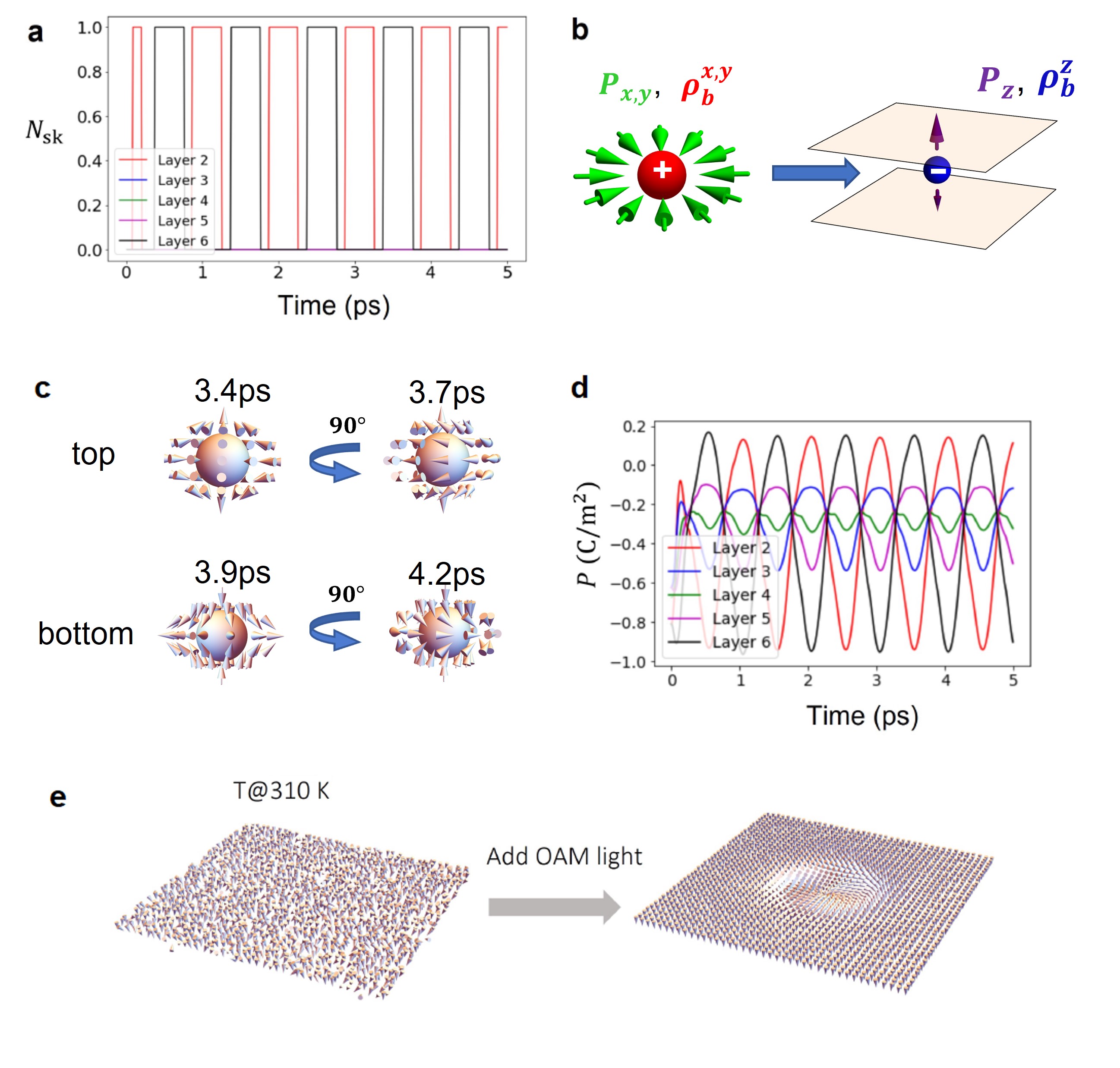
Since electronic devices are usually operated at room temperature, it is worthwhile to study how the OAM-induced-skyrmion behaves close to 300 K too. Figure. 3e shows the 3D plot of the monodomain configuration at 310 K before and after the illumination of an OAM field. Though dipoles fluctuate more at an elevated temperature, the skyrmion sustains within the focus spot out of the monodomain at 310K. As we vary the field magnitude and the screening of the depolarization field, the skyrmions are stabilized when parameters span a large range (Fig. S5 and Fig. S9). All these evidences support the robustness of the mechanism and its practicality in application. By doubling the beam width, a larger skyrmion with a dimension10 nm can be produced (Fig. S10), further demonstrating the high tunability of polar skyrmions governed by parameters of OAM field.
In summary, we predict that the nontrivial winding pattern of the field in an optical vortex beam can be imprinted in ferroelectrics, and dipolar skyrmions will emerge and evolve dynamically out of an electrostatic cooperation between microscopic bound charges and external field. Effectively, engineering OAM optical field can be considered as the input ‘writing’ process from one end, while the polarization patterns can correspond to the output ‘reading’ process at the other end and being experimentally mapped by, e.g., a piezoelectric force microscopy (PFM) technique [18]. This unusual light-matter interaction delivers a new perspective about designing fast-speed memory and logic devices.
We thank Max Mignolet, Dr. Peng Chen, Dr. Liuyang Sun, Hao Song, and Prof. Alan E. Willner for useful discussions. We acknowledge the support from the Grant MURI ETHOS W911NF-21-2-0162 from Army Research Office (ARO) and the Vannevar Bush Faculty Fellowship (VBFF) Grant No. N00014-20-1-2834 from the Department of Defense. We also acknowledge the computational support from the Arkansas High Performance Computing Center for computational resources.
References
- Nagaosa and Tokura [2013] N. Nagaosa and Y. Tokura, Topological properties and dynamics of magnetic skyrmions, Nature nanotechnology 8, 899 (2013).
- Fert et al. [2017] A. Fert, N. Reyren, and V. Cros, Magnetic skyrmions: advances in physics and potential applications, Nature Reviews Materials 2, 1 (2017).
- Neubauer et al. [2009] A. Neubauer, C. Pfleiderer, B. Binz, A. Rosch, R. Ritz, P. Niklowitz, and P. Böni, Topological hall effect in the a phase of mnsi, Physical review letters 102, 186602 (2009).
- Li et al. [2013] Y. Li, N. Kanazawa, X. Yu, A. Tsukazaki, M. Kawasaki, M. Ichikawa, X. Jin, F. Kagawa, and Y. Tokura, Robust formation of skyrmions and topological hall effect anomaly in epitaxial thin films of mnsi, Physical review letters 110, 117202 (2013).
- Jiang et al. [2015] W. Jiang, P. Upadhyaya, W. Zhang, G. Yu, M. B. Jungfleisch, F. Y. Fradin, J. E. Pearson, Y. Tserkovnyak, K. L. Wang, O. Heinonen, et al., Blowing magnetic skyrmion bubbles, Science 349, 283 (2015).
- Woo et al. [2016] S. Woo, K. Litzius, B. Krüger, M.-Y. Im, L. Caretta, K. Richter, M. Mann, A. Krone, R. M. Reeve, M. Weigand, et al., Observation of room-temperature magnetic skyrmions and their current-driven dynamics in ultrathin metallic ferromagnets, Nature materials 15, 501 (2016).
- Parkin et al. [2008] S. S. Parkin, M. Hayashi, and L. Thomas, Magnetic domain-wall racetrack memory, Science 320, 190 (2008).
- Fert et al. [2013] A. Fert, V. Cros, and J. Sampaio, Skyrmions on the track, Nature nanotechnology 8, 152 (2013).
- Zhang et al. [2015] X. Zhang, M. Ezawa, and Y. Zhou, Magnetic skyrmion logic gates: conversion, duplication and merging of skyrmions, Scientific reports 5, 1 (2015).
- Parkin and Yang [2015] S. Parkin and S.-H. Yang, Memory on the racetrack, Nature nanotechnology 10, 195 (2015).
- Wang et al. [2018] L. Wang, Q. Feng, Y. Kim, R. Kim, K. H. Lee, S. D. Pollard, Y. J. Shin, H. Zhou, W. Peng, D. Lee, et al., Ferroelectrically tunable magnetic skyrmions in ultrathin oxide heterostructures, Nature materials 17, 1087 (2018).
- Behera et al. [2022] P. Behera, M. A. May, F. Gómez-Ortiz, S. Susarla, S. Das, C. T. Nelson, L. Caretta, S.-L. Hsu, M. R. McCarter, B. H. Savitzky, et al., Electric field control of chirality, Science advances 8, eabj8030 (2022).
- Zhu et al. [2022] R. Zhu, Z. Jiang, X. Zhang, X. Zhong, C. Tan, M. Liu, Y. Sun, X. Li, R. Qi, K. Qu, et al., Dynamics of polar skyrmion bubbles under electric fields, Physical Review Letters 129, 107601 (2022).
- Nahas et al. [2015] Y. Nahas, S. Prokhorenko, L. Louis, Z. Gui, I. Kornev, and L. Bellaiche, Discovery of stable skyrmionic state in ferroelectric nanocomposites, Nature communications 6, 1 (2015).
- Gonçalves et al. [2018] M. Gonçalves, C. Escorihuela-Sayalero, P. García-Fernández, J. Junquera, and J. Íñiguez, Theoretical guidelines to create and tune electric skyrmions, arXiv preprint arXiv:1806.01617 (2018).
- Das et al. [2019] S. Das, Y. Tang, Z. Hong, M. Gonçalves, M. McCarter, C. Klewe, K. Nguyen, F. Gómez-Ortiz, P. Shafer, E. Arenholz, et al., Observation of room-temperature polar skyrmions, Nature 568, 368 (2019).
- Nahas et al. [2020] Y. Nahas, S. Prokhorenko, Q. Zhang, V. Govinden, N. Valanoor, and L. Bellaiche, Topology and control of self-assembled domain patterns in low-dimensional ferroelectrics, Nature communications 11, 1 (2020).
- Han et al. [2022] L. Han, C. Addiego, S. Prokhorenko, M. Wang, H. Fu, Y. Nahas, X. Yan, S. Cai, T. Wei, Y. Fang, et al., High-density switchable skyrmion-like polar nanodomains integrated on silicon, Nature 603, 63 (2022).
- Dzyaloshinsky [1958] I. Dzyaloshinsky, A thermodynamic theory of “weak” ferromagnetism of antiferromagnetics, Journal of physics and chemistry of solids 4, 241 (1958).
- Moriya [1960] T. Moriya, Anisotropic superexchange interaction and weak ferromagnetism, Physical review 120, 91 (1960).
- Yadav et al. [2016] A. Yadav, C. Nelson, S. Hsu, Z. Hong, J. Clarkson, C. Schlepütz, A. Damodaran, P. Shafer, E. Arenholz, L. Dedon, et al., Observation of polar vortices in oxide superlattices, Nature 530, 198 (2016).
- Allen et al. [1992] L. Allen, M. W. Beijersbergen, R. Spreeuw, and J. Woerdman, Orbital angular momentum of light and the transformation of laguerre-gaussian laser modes, Physical review A 45, 8185 (1992).
- Shen et al. [2019] Y. Shen, X. Wang, Z. Xie, C. Min, X. Fu, Q. Liu, M. Gong, and X. Yuan, Optical vortices 30 years on: Oam manipulation from topological charge to multiple singularities, Light: Science & Applications 8, 1 (2019).
- Rosen et al. [2022] G. F. Q. Rosen, P. I. Tamborenea, and T. Kuhn, Interplay between optical vortices and condensed matter, Reviews of Modern Physics 94, 035003 (2022).
- He et al. [1995] H. He, M. Friese, N. Heckenberg, and H. Rubinsztein-Dunlop, Direct observation of transfer of angular momentum to absorptive particles from a laser beam with a phase singularity, Physical review letters 75, 826 (1995).
- Paterson et al. [2001] L. Paterson, M. P. MacDonald, J. Arlt, W. Sibbett, P. Bryant, and K. Dholakia, Controlled rotation of optically trapped microscopic particles, Science 292, 912 (2001).
- MacDonald et al. [2002] M. P. MacDonald, L. Paterson, K. Volke-Sepulveda, J. Arlt, W. Sibbett, and K. Dholakia, Creation and manipulation of three-dimensional optically trapped structures, Science 296, 1101 (2002).
- Grier [2003] D. G. Grier, A revolution in optical manipulation, nature 424, 810 (2003).
- Sederberg et al. [2020] S. Sederberg, F. Kong, F. Hufnagel, C. Zhang, E. Karimi, and P. B. Corkum, Vectorized optoelectronic control and metrology in a semiconductor, Nature Photonics 14, 680 (2020).
- Ji et al. [2020] Z. Ji, W. Liu, S. Krylyuk, X. Fan, Z. Zhang, A. Pan, L. Feng, A. Davydov, and R. Agarwal, Photocurrent detection of the orbital angular momentum of light, Science 368, 763 (2020).
- Fujita and Sato [2017a] H. Fujita and M. Sato, Ultrafast generation of skyrmionic defects with vortex beams: Printing laser profiles on magnets, Physical Review B 95, 054421 (2017a).
- Fujita and Sato [2017b] H. Fujita and M. Sato, Encoding orbital angular momentum of light in magnets, Physical Review B 96, 060407 (2017b).
- Feldtkeller [1965] E. Feldtkeller, Mikromagnetisch stetige und unstetige magnetisierungskonfigurationen, Zeitschrift fur Angewandte Physik 19, 530 (1965).
- Thiaville et al. [2003] A. Thiaville, J. M. García, J. Miltat, T. Schrefl, et al., Micromagnetic study of bloch-point-mediated vortex core reversal, Physical Review B 67, 094410 (2003).
- Kornev et al. [2004] I. Kornev, H. Fu, and L. Bellaiche, Ultrathin films of ferroelectric solid solutions under a residual depolarizing field, Physical review letters 93, 196104 (2004).
- Ponomareva et al. [2005a] I. Ponomareva, I. Naumov, I. Kornev, H. Fu, and L. Bellaiche, Atomistic treatment of depolarizing energy and field in ferroelectric nanostructures, Physical Review B 72, 140102 (2005a).
- Ponomareva et al. [2005b] I. Ponomareva, I. Naumov, and L. Bellaiche, Low-dimensional ferroelectrics under different electrical and mechanical boundary conditions: Atomistic simulations, Physical Review B 72, 214118 (2005b).
- Gruverman et al. [2008] A. Gruverman, D. Wu, H. Fan, I. Vrejoiu, M. Alexe, R. Harrison, and J. Scott, Vortex ferroelectric domains, Journal of Physics: Condensed Matter 20, 342201 (2008).
- Tang et al. [2015] Y. Tang, Y. Zhu, X. Ma, A. Y. Borisevich, A. N. Morozovska, E. A. Eliseev, W. Wang, Y. Wang, Y. Xu, Z. Zhang, et al., Observation of a periodic array of flux-closure quadrants in strained ferroelectric pbtio3 films, Science 348, 547 (2015).
- Zhang et al. [2017] Q. Zhang, L. Xie, G. Liu, S. Prokhorenko, Y. Nahas, X. Pan, L. Bellaiche, A. Gruverman, and N. Valanoor, Nanoscale bubble domains and topological transitions in ultrathin ferroelectric films, Advanced Materials 29, 1702375 (2017).
- Shintani et al. [2016] K. Shintani, K. Taguchi, Y. Tanaka, and Y. Kawaguchi, Spin and charge transport induced by a twisted light beam on the surface of a topological insulator, Physical Review B 93, 195415 (2016).
- Zhou et al. [2015] Y. Zhou, E. Iacocca, A. A. Awad, R. K. Dumas, F. Zhang, H. B. Braun, and J. Åkerman, Dynamically stabilized magnetic skyrmions, Nature communications 6, 1 (2015).
- Luo and You [2021] S. Luo and L. You, Skyrmion devices for memory and logic applications, APL Materials 9, 050901 (2021).
- Hsu et al. [2017] P.-J. Hsu, A. Kubetzka, A. Finco, N. Romming, K. Von Bergmann, and R. Wiesendanger, Electric-field-driven switching of individual magnetic skyrmions, Nature nanotechnology 12, 123 (2017).
See pages 1, of SI020223.pdf See pages 2, of SI020223.pdf See pages 3, of SI020223.pdf See pages 4, of SI020223.pdf See pages 5, of SI020223.pdf See pages 6, of SI020223.pdf See pages 7, of SI020223.pdf See pages 8, of SI020223.pdf See pages 9, of SI020223.pdf See pages 10, of SI020223.pdf See pages 11, of SI020223.pdf See pages 12, of SI020223.pdf See pages 13, of SI020223.pdf See pages 14, of SI020223.pdf See pages 15, of SI020223.pdf See pages 16, of SI020223.pdf See pages 17, of SI020223.pdf See pages 18, of SI020223.pdf See pages 19, of SI020223.pdf See pages 20, of SI020223.pdf See pages 21, of SI020223.pdf See pages 22, of SI020223.pdf