Manipulating coherence of near-field thermal radiation in time-modulated systems
Abstract
We show that the spatial coherence of thermal radiation can be manipulated in time-modulated photonic systems supporting surface polaritons. We develop a fluctuational electrodynamics formalism for such systems to calculate the cross-spectral density tensor of the emitted thermal electromagnetic fields in the near-field regime. Our calculations indicate that, due to time-modulation, spatial coherence can be transferred between different frequencies, and correlations between different frequency components become possible. All these effects are unique to time-modulated systems. We also show that the decay rate of optical emitters can be controlled in the proximity of such time-modulated structure. Our findings open a promising avenue toward coherence control in thermal radiation, dynamical thermal imaging, manipulating energy transfer among thermal or optical emitters, efficient near-field radiative cooling, and engineering spontaneous emission rates of molecules.
Controlling thermal emission is crucial for many applications, such as passive radiative cooling Raman et al. (2014), solar thermophotovoltaic energy conversion Lenert et al. (2014), and incandescent lighting Liu et al. (2011); Ilic et al. (2016). Recent developments in near-field nanophotonics have provided new possibilities for enhanced radiative cooling Guha et al. (2012), thermophotovoltaic energy conversion Laroche et al. (2006); Mittapally et al. (2021); Basu et al. (2009), and imaging Kittel et al. (2005). Near-field radiative heat transfer is also of fundamental importance to explore fluctuation physics at nanoscale Carminati and Greffet (1999); Joulain et al. (2005); Polder and Van Hove (1971); Volokitin and Persson (2007); Ben-Abdallah and Biehs (2014); Otey et al. (2010); Kralik et al. (2012); Rousseau et al. (2009); Kim et al. (2015); Song et al. (2015); Manjavacas and García de Abajo (2012); Zhao et al. (2017); Shi et al. (2015); Narayanaswamy et al. (2008); Papadakis et al. (2019); St-Gelais et al. (2016); Bimonte et al. (2017); Sääskilahti et al. (2014); Ben-Abdallah et al. (2011); Asheichyk and Krüger (2022) in various aspects, including vacuum friction Manjavacas and García de Abajo (2010); Zhao et al. (2012), persistent heat current at equilibrium Zhu and Fan (2016), and ultrafast radiative heat transfer Yu et al. (2017).
Most studies on controlling thermal emission are carried out with passive systems. But recent works have pointed to new effects when active systems are considered Chen et al. (2015); Zhu et al. (2019); Buddhiraju et al. (2020); Khandekar et al. (2015a, b). For example, in Ref. Buddhiraju et al. (2020), temporal modulation of the material permittivity is used to initiate an energy transfer between two optical resonances and to achieve active cooling in the far-field regime. Since, in the broader photonics context, temporal modulation has created promising new opportunities for photon management, such as frequency conversion Shcherbakov et al. (2019); Ramaccia et al. (2019), optical isolation Yu and Fan (2009); Sounas and Alu (2017), and optical temporal aiming Pacheco-Peña and Engheta (2020), it should be of interest to further explore the consequence of temporal modulation on thermal radiation.
A key characteristics of thermal radiation is its coherence property. Conventional thermal emitters can be well approximated by a blackbody, and its thermally emitted electromagnetic fields are incoherent in the far-field regime. In contrast, in the near-field regime, an enhanced coherence of thermal radiation from planar structures made of either noble metals or polar materials has been theoretically proposed Carminati and Greffet (1999) and experimentally demonstrated De Wilde et al. (2006). This near-field coherence enhancement is due to the surface plasmon or phonon polaritons supported by these structures, and occurred only at the frequencies near the surface polariton resonances. Further nanophotonic structuring can transfer the enhanced coherence into the far field, leading to a coherent emission of light from thermal sources Greffet et al. (2002). However, all existing studies on coherence properties of thermal radiation consider only passive systems.
In this work, we study the spatial coherence of thermal radiation in time-modulated active systems. As an example, we consider a planar structure consisting of a plasmon or phonon polaritonic substrate and a dielectric thin film. We study the coherence properties of its thermally emitted electromagnetic fields in the near-field regime when the dielectric thin film is undergoing a permittivity modulation. Our study reveals several unique characteristics in the coherence properties. We show that the strong coherence can be observed at frequencies away from the surface polariton resonances, due to the transfer of coherence as induced by temporal modulation. Also, the temporally modulated system exhibits cross-frequency correlation, i.e., coherence between thermal radiations at different frequencies. None of these properties exist in passive structures. To study this system, we have developed a fluctuational electrodynamics formalism for time-modulated systems. Our formalism further reveals that the local density of states in the near field can be strongly affected due to temporal modulation. Thus, temporal modulation enables a novel pathway to control the decay rate of optical emitters.
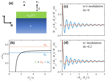
As the model system in this paper, in Fig. 1(a), we consider a time-modulated lossless layer (green region) on top of a semi-infinite substrate composed of a Drude metal (blue region). The permittivity of the Drude metal is assumed to be , with eV and meV, and that of the time-modulated layer is , with the static permittivity, the modulation strength, and the modulation frequency. Here, the modulated layer is assumed be lossless. Thus, all thermal radiation is sourced from the Drude metal. We assume that the top of the modulated layer is at , and the thickness of the time-modulated layer is m. In the frequency domain, the thermally emitted electric fields in the vacuum region () can be obtained from the fluctuating currents residing in the Drude metal as
| (1) |
where is the Green’s function of the time-modulated system. In a static system, we have . In contrast, for the time-modulated system with a single modulation frequency as considered here, the Green’s function is given by with , and Eq. 1 becomes
| (2) |
In this work, the focus is on the spatial coherence of thermally emitted fields. The physical quantity under investigation is the electric-field cross-spectral density tensor , given by Mandel and Wolf (1995); Carminati and Greffet (1999)
| (3) |
which characterizes the spatial correlation of the thermally emitted electric fields at two points and and at two frequencies and , respectively. The superscript * in Eq. 3 denotes the complex conjugate operation. By using the fluctuation-dissipation theorem, from Eqs. 2 and 3, the cross-spectral density tensor of the electric fields in the upper half space can be calculated as
| (4) |
where with . The integration over is carried out inside the substrate (Drude metal here). We assume K throughout this study. As seen in Eq. 2, an important aspect is that the thermal electromagnetic field at a frequency has contributions from sources at all frequencies . Consequently, as shown in Eq. 4, electric fields at two frequencies and can correlate with each other if , with being an integer. Such cross-frequency correlation for arises from the photon frequency conversion as induced by the modulation with a frequency . When Eq. 4 is applied to static systems, only the term contributes and thus .
Because the system displayed in Fig. 1(a) is translationally invariant in plane, Eq. 4 can be written in -space as
| (5) |
where in-plane wave vectors , in-plane coordinates , and represents the Fourier transform of in -space. We have developed a fluctuational electrodynamics formalism for time-modulated systems to calculate and .
In Fig. 1(b), we present the dispersion of the surface plasmon mode, supported in the system. We consider two frequencies THz and THz separated by THz. We use this value of throughout this work unless otherwise specified. The structure supports a surface plasmon mode at but not at , as indicated in Fig. 1(b). Using Eq. 5, we obtain for in a plane at a subwavelength distance m (approximately 1/20 of the wavelength) above the modulated layer, as shown in Fig. 1(a).
We first explore for . In Fig. 1(c), normalized is plotted against the normalized in-plane separation distance for the frequencies and without time modulation (i.e., ). Because the surface plasmon dominates the electromagnetic response in the near-field regime, the correlation length is much larger at where the surface plasmon mode is present (blue curve) than at where no surface plasmon mode is available (red curve). The effect of such enhanced correlation length due to the presence of surface plasmons has been previously reported in Ref. Carminati and Greffet (1999). In contrast, when the time modulation is present [Fig. 1(d)], we find the correlation length at (red curve) is drastically enhanced as compared with the unmodulated case shown in Fig. 1(c). In the meanwhile, a slightly decreased correlation length at (blue curve) is observed [Fig. 1(d)]. The results here indicate that the coherence is transferred from to due to time modulation.
In order to illustrate better the underlining mechanism behind results shown in Fig. 1, based on Eq. 5, we define
| (6) |
is related to as
for . Here, can be associated with a spectrally resolved transition coefficient (in the unit of ) from to for each .
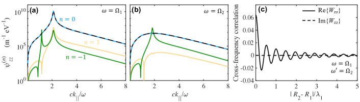
In Fig. 2(a), we plot as a function of for , 0, and 1 at a fixed emitted field frequency under the same type of time modulation as used in Fig. 1(d). The contributions to from higher order () components are negligible. The dominant contribution is from the component (i.e., ). The spectrum of the component for the modulated system [blue curve in Fig. 2(a)] is very similar to that of the unmodulated system [black dashed curve in Fig. 2(a)]. Both spectra peaks at , which corresponds to the wave vector of the surface plasmon mode at , as shown in Fig. 1(b). Thus both spectra are dominated by the contribution from the surface plasmon mode. As a result, in real space, the correlation function oscillates at a period of approximately for both the modulated and unmodulated cases, shown as the blue curve in Fig. 1(c) and (d), respectively. The component represents a transition from (thermal source frequency in the metal) to (emitted field frequency in vacuum). From Fig. 1(b), we observe that the system also supports a surface plasmon mode at with . Thus the spectrum of component features two peaks around and due to contributions from surface plasmon modes at and , respectively. Note that this transition between to is not phase-matched. The modulation is spatially uniform parallel to the surface, and yet the wave vectors of the surface plasmon modes at and are different. Consequently, the strength of the transition is weak and thus the peak value of is much smaller than that of . The spectrum of component features only one peak around instead of two peaks because no surface plasmon mode is available at (i.e., ).
Significant differences in the behaviors of can be found at . For the modulated system, the spectrum of its component [blue curve in Fig. 2(b)] is very similar to that of the unmodulated system [black dashed line in Fig. 2(b)]. Also, both the and components do not exhibit any peaks since there is no surface plasmon mode at either or . On the other hand, the components exhibit one peak around because of the presence of the surface plasmon mode at . Also, because of the presence of the surface plasmon modes, the component dominates over the and components. Consequently, at , the modulated and the unmodulated systems exhibit completely different behavior in their coherence properties. In the unmodulated system, there is no long-range correlation behavior [Fig. 1(c), red curve] since there is no surface plasmon mode at . In the modulated system, there is a distinct long-range correlation behavior [Fig. 1(d), red curve]. As a result, the correlation function exhibits a corresponding oscillation period around in real space [Fig. 1(d), red curve]. The results here indicate that time modulation can transfer coherence from one frequency to the others and hence can be used to drastically enhance the coherence of thermal radiation.
In Fig. 2(c) we plot the cross-frequency correlation , which describes the correlation of the electric fields at two different frequencies and . The existence of such correlation for fields at two different frequencies arises from the photonic transition as induced by dynamic modulation, and is a unique effect in time-modulated systems. Such cross-frequency correlation identically vanishes for passive systems. In Fig. 2(c), a rather long correlation length can be seen, as a consequence of the coherence enhancement as provided by the surface plasmon mode at . Note that is now a complex quantity for , and in Fig. 2(c) both its real and imaginary parts are plotted.
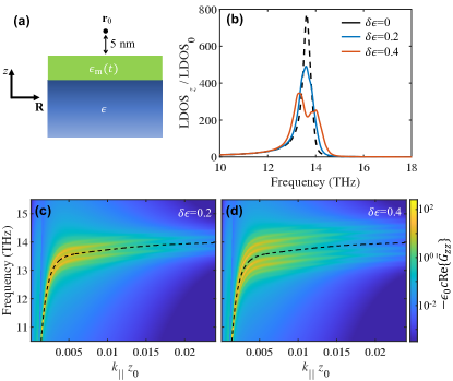
In addition to control the coherence properties, the time modulation can also be used to manipulate the local density of optical states (LDOS). The LDOS is closely related to the energy density of the emitted thermal electromagnetic fields. Moreover, by controlling the LDOS, the decay rate of an emitter in the vicinity of structure can be manipulated Novotny and Hecht (2006); Lu et al. (2014); Yu et al. (2020). As shown in Fig. 3(a), the system under investigation is the same as that used in Fig. 1(a). Here we consider the contribution to the LDOS for the -component of the electric field, at a location which is at nm above the material-vacuum interface. Such a contribution is relevant for the spontaneous emission rate of a -polarized dipole located at . In time-modulated systems considered here, the LDOS can be calculated as
| (7) |
We have normalized the LDOS to its value in free space .
In Fig. 3(b), LDOS spectra for different modulation strengths are plotted. Without time modulation, the spectrum consists of a single peak around 13.6 THz (black dashed curve), as a result of the excitation of the surface plasmon resonance. In the presence of time modulation with , the spectrum consists of one broadened and damped peak (blue curve). With further increasing the modulation strength to , the spectrum further broadens and splits, and its peak amplitude further decreases (red curve).
To analyze the LDOS spectra, we plot , which appears in the integrand of Eq. 7, as a function of frequency and in-plane wave number in Fig. 3(c) and (d). In the absence of modulation, this quantity should peak at the dispersion relation of the surface plasmon, as indicated by the black dashed line in Fig. 3(c) and (d). In the presence of the modulation, this quantity peaks at the Floquet band structure of the system. For the case of , in addition to the band at the dispersion relation of the surface plasmon, we see two prominent bands, with frequencies above and below the surface plasmon band respectively, due to the modulation. For the case of , additional Floquet bands with frequencies above and below the surface plasmon band become visible. The broadening of the peaks of in the LDOS is directly related to the Floquet band structure of the system.
We remark that such time-modulation induced coherence transfer can be also achieved with a lower (sub-terahertz) modulation frequency and a smaller modulation strength (with around 0.01). The state-of-the-art electro-optical modulation with a response bandwidth approaching terahertz Huang et al. (2012); Mercante et al. (2018); Ummethala et al. (2019) can thus be exploited for this purpose. Moreover, in the present work we consider only direct photonic transition since our modulation is spatially uniform along the propagation direction of the surface plasmon. Additional opportunities may occur if one considers an indirect photonic transition Yu and Fan (2009) where the modulation is of the form of with . Such a modulation may significantly enhance the coherence transition by coupling two surface plasmon modes at different frequencies together. Finally, the same concept and mechanism can be used to achieve the coherence transfer in systems based on surface phonon polaritons as well.
In summary, we have shown that the spatial coherence of thermal radiation can be manipulated by temporally modulating the permittivity of the dielectric layer in a polaritonic structure. This is initiated by the time-modulation induced transition of energy and coherence from multiple thermal source frequencies to the emitted thermal radiation frequency. As a result, correlations between two different radiation frequencies become possible in such system. Finally, we have also shown that the LDOS spectra can be controlled in the proximity of the time-modulated structure, due to the creation of the Floquet band structure in this system. Our findings open an exciting route toward coherence control of radiation from nanoscale thermal sources, dynamical thermal imaging, manipulating energy transfer among remotely located thermal or optical emitters, enhanced near-field radiative cooling, and modulating spontaneous emission rates of molecules.
This work has been supported by a MURI program from the U. S. Army Research Office (Grant No. W911NF-19-1-0279).
References
- Raman et al. (2014) A. P. Raman, M. A. Anoma, L. Zhu, E. Rephaeli, and S. Fan, Nature 515, 540 (2014).
- Lenert et al. (2014) A. Lenert, D. M. Bierman, Y. Nam, W. R. Chan, I. Celanović, M. Soljačić, and E. N. Wang, Nature Nanotechnology 9, 126 (2014).
- Liu et al. (2011) X. Liu, T. Tyler, T. Starr, A. F. Starr, N. M. Jokerst, and W. J. Padilla, Phys. Rev. Lett. 107, 045901 (2011).
- Ilic et al. (2016) O. Ilic, P. Bermel, G. Chen, J. D. Joannopoulos, I. Celanovic, and M. Soljačić, Nature Nanotechnology 11, 320 (2016).
- Guha et al. (2012) B. Guha, C. Otey, C. B. Poitras, S. Fan, and M. Lipson, Nano Lett. 12, 4546 (2012).
- Laroche et al. (2006) M. Laroche, R. Carminati, and J.-J. Greffet, Journal of Applied Physics 100, 063704 (2006).
- Mittapally et al. (2021) R. Mittapally, B. Lee, L. Zhu, A. Reihani, J. W. Lim, D. Fan, S. R. Forrest, P. Reddy, and E. Meyhofer, Nature Communications 12, 4364 (2021).
- Basu et al. (2009) S. Basu, Z. M. Zhang, and C. J. Fu, Int. J. Energy Res. 33, 1203 (2009).
- Kittel et al. (2005) A. Kittel, W. Müller-Hirsch, J. Parisi, S. A. Biehs, D. Reddig, and M. Holthaus, Phys. Rev. Lett. 95, 224301 (2005).
- Carminati and Greffet (1999) R. Carminati and J. J. Greffet, Phys. Rev. Lett. 82, 1660 (1999).
- Joulain et al. (2005) K. Joulain, J.-P. Mulet, F. Marquier, R. Carminati, and J.-J. Greffet, Surface Science Reports 57, 59 (2005).
- Polder and Van Hove (1971) D. Polder and M. Van Hove, Phys. Rev. B 4, 3303 (1971).
- Volokitin and Persson (2007) A. I. Volokitin and B. N. J. Persson, Rev. Mod. Phys. 79, 1291 (2007).
- Ben-Abdallah and Biehs (2014) P. Ben-Abdallah and S.-A. Biehs, Phys. Rev. Lett. 112, 044301 (2014).
- Otey et al. (2010) C. R. Otey, W. T. Lau, S. Fan, et al., Physical Review Letters 104, 154301 (2010).
- Kralik et al. (2012) T. Kralik, P. Hanzelka, M. Zobac, V. Musilova, T. Fort, and M. Horak, Physical Review Letters 109, 224302 (2012).
- Rousseau et al. (2009) E. Rousseau, A. Siria, G. Jourdan, S. Volz, F. Comin, J. Chevrier, and J. J. Greffet, Nat. Photon. 3, 514 (2009).
- Kim et al. (2015) K. Kim, B. Song, V. Fernández-Hurtado, W. Lee, W. Jeong, L. Cui, D. Thompson, J. Feist, M. H. Reid, F. J. García-Vidal, et al., Nature 528, 387 (2015).
- Song et al. (2015) B. Song, Y. Ganjeh, S. Sadat, D. Thompson, A. Fiorino, V. Fernández-Hurtado, J. Feist, F. J. Garcia-Vidal, J. C. Cuevas, P. Reddy, et al., Nature Nanotechnology 10, 253 (2015).
- Manjavacas and García de Abajo (2012) A. Manjavacas and F. J. García de Abajo, Phys. Rev. B 86, 075466 (2012).
- Zhao et al. (2017) B. Zhao, B. Guizal, Z. M. Zhang, S. Fan, and M. Antezza, Phys. Rev. B 95, 245437 (2017).
- Shi et al. (2015) J. Shi, B. Liu, P. Li, L. Y. Ng, and S. Shen, Nano Lett. 15, 1217 (2015).
- Narayanaswamy et al. (2008) A. Narayanaswamy, S. Shen, and G. Chen, Phys. Rev. B 78, 115303 (2008).
- Papadakis et al. (2019) G. T. Papadakis, B. Zhao, S. Buddhiraju, and S. Fan, ACS Photonics 6, 709 (2019).
- St-Gelais et al. (2016) R. St-Gelais, L. Zhu, S. Fan, and M. Lipson, Nat. Nanotechn. 11, 515 (2016).
- Bimonte et al. (2017) G. Bimonte, T. Emig, M. Kardar, and M. Krüger, Annual Review of Condensed Matter Physics 8, 119 (2017).
- Sääskilahti et al. (2014) K. Sääskilahti, J. Oksanen, and J. Tulkki, Phys. Rev. B 89, 134301 (2014).
- Ben-Abdallah et al. (2011) P. Ben-Abdallah, S. A. Biehs, and K. Joulain, Phys. Rev. Lett. 107, 114301 (2011).
- Asheichyk and Krüger (2022) K. Asheichyk and M. Krüger, Phys. Rev. Lett. 129, 170605 (2022).
- Manjavacas and García de Abajo (2010) A. Manjavacas and F. J. García de Abajo, Phys. Rev. Lett. 105, 113601 (2010).
- Zhao et al. (2012) R. Zhao, A. Manjavacas, F. J. García de Abajo, and J. B. Pendry, Phys. Rev. Lett. 109, 123604 (2012).
- Zhu and Fan (2016) L. Zhu and S. Fan, Phys. Rev. Lett. 117, 134303 (2016).
- Yu et al. (2017) R. Yu, A. Manjavacas, and F. J. García de Abajo, Nat. Commun. 8, 2 (2017).
- Chen et al. (2015) K. Chen, P. Santhanam, S. Sandhu, L. Zhu, and S. Fan, Physical Review B 91, 134301 (2015).
- Zhu et al. (2019) L. Zhu, A. Fiorino, D. Thompson, R. Mittapally, E. Meyhofer, and P. Reddy, Nature 566, 239 (2019).
- Buddhiraju et al. (2020) S. Buddhiraju, W. Li, and S. Fan, Physical Review Letters 124, 077402 (2020).
- Khandekar et al. (2015a) C. Khandekar, A. Pick, S. G. Johnson, and A. W. Rodriguez, Phys. Rev. B 91, 115406 (2015a).
- Khandekar et al. (2015b) C. Khandekar, Z. Lin, and A. W. Rodriguez, Applied Physics Letters 106, 151109 (2015b).
- Shcherbakov et al. (2019) M. R. Shcherbakov, K. Werner, Z. Fan, N. Talisa, E. Chowdhury, and G. Shvets, Nature Communications 10, 1345 (2019).
- Ramaccia et al. (2019) D. Ramaccia, D. L. Sounas, A. Alu, A. Toscano, and F. Bilotti, IEEE Transactions on Antennas and Propagation 68, 1607 (2019).
- Yu and Fan (2009) Z. Yu and S. Fan, Nature Photonics 3, 91 (2009).
- Sounas and Alu (2017) D. L. Sounas and A. Alu, Nature Photonics 11, 774 (2017).
- Pacheco-Peña and Engheta (2020) V. Pacheco-Peña and N. Engheta, Light: Science & Applications 9, 1 (2020).
- De Wilde et al. (2006) Y. De Wilde, F. Formanek, R. Carminati, B. Gralak, P.-A. Lemoine, K. Joulain, J.-P. Mulet, Y. Chen, and J.-J. Greffet, Nature 444, 740 (2006).
- Greffet et al. (2002) J. J. Greffet, R. Carminati, K. Joulain, J. P. Mulet, S. Mainguy, and Y. Chen, Nature 416, 61 (2002).
- Mandel and Wolf (1995) L. Mandel and E. Wolf, Optical Coherence and Quantum Optics (Cambridge University Press, Cambridge, 1995).
- Novotny and Hecht (2006) L. Novotny and B. Hecht, Principles of Nano-Optics (Cambridge University Press, New York, 2006).
- Lu et al. (2014) D. Lu, J. J. Kan, E. E. Fullerton, and Z. Liu, Nat. Nanotech. 9, 48 (2014).
- Yu et al. (2020) R. Yu, R. Alaee, R. W. Boyd, and F. J. G. de Abajo, Physical Review Letters 125, 037403 (2020).
- Huang et al. (2012) H. Huang, S. Nuccio, Y. Yue, J.-Y. Yang, Y. Ren, C. Wei, G. Yu, R. Dinu, D. Parekh, C. Chang-Hasnain, et al., Journal of Lightwave Technology 30, 3647 (2012).
- Mercante et al. (2018) A. J. Mercante, S. Shi, P. Yao, L. Xie, R. M. Weikle, and D. W. Prather, Opt. Express 26, 14810 (2018).
- Ummethala et al. (2019) S. Ummethala, T. Harter, K. Koehnle, Z. Li, S. Muehlbrandt, Y. Kutuvantavida, J. Kemal, P. Marin-Palomo, J. Schaefer, A. Tessmann, et al., Nature Photonics 13, 519 (2019).