RIS-Assisted Interference Mitigation
for Uplink NOMA
††thanks:
Abstract
Non-orthogonal multiple access (NOMA) has become a promising technology for next-generation wireless communications systems due to its capability to provide access for multiple users on the same resource. In this paper, we consider an uplink power-domain NOMA system aided by a reconfigurable intelligent surface (RIS) in the presence of a jammer that aims to maximize its interference on the base station (BS) uplink receiver. We consider two kinds of RISs, a regular RIS whose elements can only change the phase of the incoming wave, and an RIS whose elements can also attenuate the incoming wave. Our aim is to minimize the total power transmitted by the user terminals under quality-of-service constraints by controlling both the propagation from the users and the jammer to the BS with help of the RIS. The resulting objective function and constraints are both non-linear and non-convex, so we address this problem using numerical optimization. Our numerical results show that the RIS can help to dramatically reduce the per user required transmit power in an interference-limited scenario.
Index Terms:
NOMA, RIS, Phase shift, OptimizationI Introduction
Recently, the rapid development of the internet of things (IoT), multimedia applications, and vehicle-to-everything (V2X) communications have led to an increase in the number of user equipment (UE) and the need for enhanced data-rates for 5G-and-beyond mobile wireless networks [1]. To address these demands, some potential candidate technologies have been proposed including massive multiple-input multiple-output (MIMO) antenna arrays [2], ultra-dense networks [3], millimeter wave communications [4], and non-orthogonal multiple access (NOMA) [5]. All of these techniques are useful for enabling massive connectivity among many wireless devices. NOMA is of particular interest because it allows multiple users to share the same orthogonal time-, frequency-, spatial- and code-domain resource blocks [6]. In [7] NOMA was shown to give an improvement in system throughput and user-fairness for a single-input single-output (SISO) channel compared to OFDMA. Since then, many researchers have investigated the benefits of NOMA for next-generation radio access techniques. However, there is substantially less work on uplink NOMA, and there is a lack of work addressing the reliability of NOMA in the presence of an active jammer. On the other hand, the use of RIS has emerged as a unique technology for improving both spectral and energy efficiency. An RIS consists of an array of elements whose reflective properties can be individually controlled, enabling some degree of control of the wireless propagation environment [9]. In a conventional RIS implementation, it is the phase shift of the reflection coefficient of each element that is adjusted in order to achieve the desired effect on the wireless channels. More recently, researchers have also studied RIS architectures where both the phase shift and the attenuation of the reflection coefficient of each element can be individually controlled, so-called absorptive RIS (A-RIS). In this latter case, the energy absorbed by the A-RIS can be refracted to directions on the other side of the surface [16],[17] or sampled using an active radio frequency (RF) receiver for channel estimation or sensing [18],[20]. RIS technology has been applied in many different types of wireless communications scenarios, including NOMA [8]. However, while the use of conventional phase-shift-only RIS has been proposed for NOMA applications with the goal of improving spectral efficiency, to our knowledge there is no work reported on using A-RIS with NOMA, nor on using RIS to mitigate the impact of external interference (e.g. jamming) on NOMA performance. In this paper, we address these two avenues and show how a regular RIS and an A-RIS can provide improved rejection of a multi-antenna jammer on a simple two-user uplink NOMA system. The paper outline is as follows. In Section II we deepen the analysis of related works on NOMA and RIS. In Section III we detail our targeted scenario, provide our RIS-assisted NOMA system model and define our targeted optimization problem. In Section IV we present our obtained results using numerical optimization on RIS-assisted jammer interference mitigation in uplink NOMA, and we summarize our findings in Section V.
II Overview of NOMA and RIS
II-A Related work
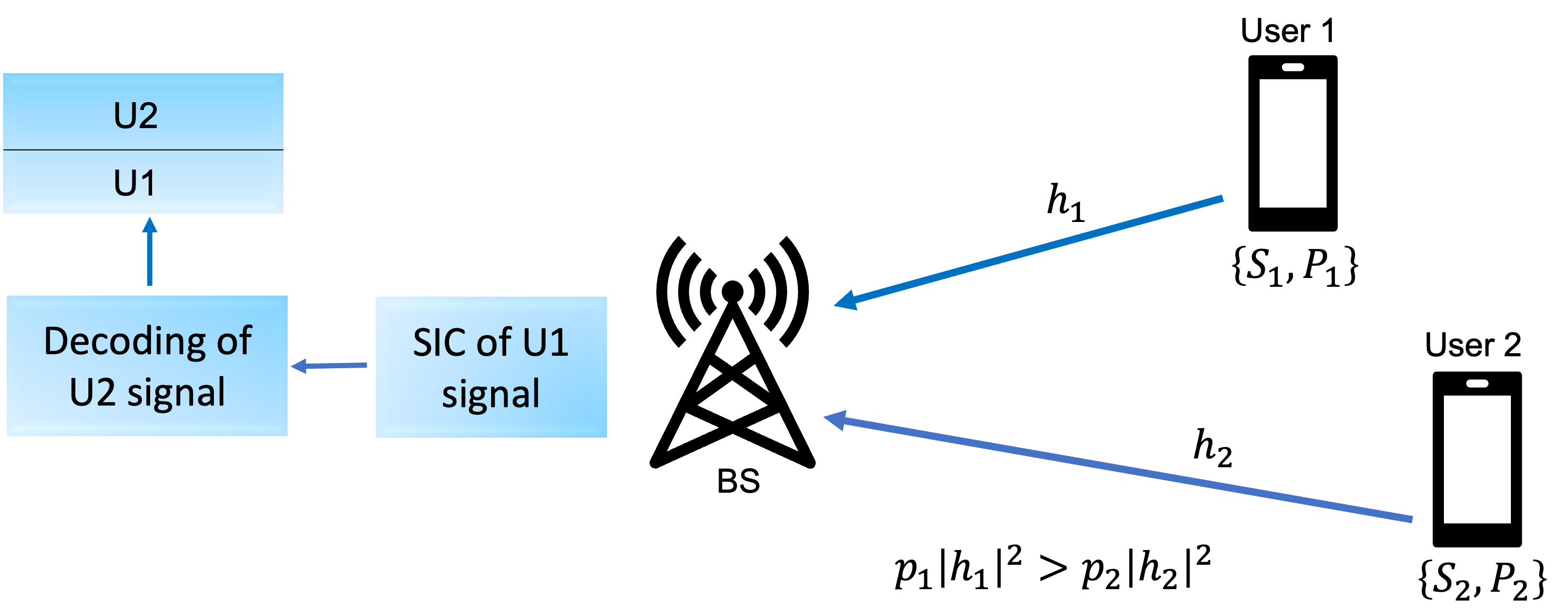
(1) Literature on NOMA: NOMA is an interesting technique since it enables multiple access for users in the same resource. Generally, NOMA is divided into two main classes: power-domain and code-domain [10]. Power-domain NOMA exploits situations where the users have different path loss levels. In downlink NOMA this implies that the users nearer to the base station (BS) typically have better channel conditions compared to distant users, who require higher transmission power to mitigate the higher path loss. The idea behind power-domain NOMA is that the users nearer the BS can employ successive interference cancellation (SIC) to remove the strong signal destined for the remote users before decoding their own signal [11]. In uplink NOMA, which is the focus of this paper, the BS can similarly employ SIC for the nearer users to remove those before decoding the signals for the remote users. However, as illustrated in Fig. 1 for the case of two users, the SIC condition needs to include both the individual users’ transmit power , as well as the channel gain for paired users in the same resource. The superiority of NOMA over conventional OMA is derived from the improved spectral efficiency due to the sharing of time/frequency/space/code resources, its allocation of different quality-of-service (QoS) levels to users based on power level allocation, and the fact that it supports massive connectivity, lower latency and an enhanced cell-edge user experience [12]. NOMA technology has been combined with other technologies such as massive MIMO, cognitive-communication, integrated access and backhaul (IAB), and RIS. (2) Literature on RIS: An RIS is a surface consisting of electromagnetic material. The surface usually consists of a large number of low-cost reflecting elements whose properties can be controlled. In a conventional RIS design, the phase of the reflection coefficient of each element is controlled in order to enable modification of the propagated waves [13]. More recently, RIS designs have been proposed that enable control of both the phase and the attenuation of each element, providing additional degrees of freedom for shaping the resulting wave field [18],[21]. RIS technology has been proposed for many different types of wireless communication scenarios, including NOMA [8],[13]. It has been shown that the performance of NOMA systems can be improved by increasing the number of reflecting elements [14], and the spectral efficiency can be significantly enhanced with RIS-assisted NOMA, compared to NOMA without RIS and traditional OMA [8].
III RIS-NOMA Network: System Model
In this section, we first describe the system and signal model for our considered RIS-NOMA system.
III-A System Model

We consider an uplink transmission RIS-NOMA system where the BS is equipped with a single-antenna, an RIS with elements, a jammer with antennas, and two single antenna users using PD-NOMA, as shown in Fig. 2. The received signal at the BS can be written as
| (1) |
where denotes the direct channels between the users and the BS, is the symbol transmitted by user , denotes the channel vector between the RIS and the BS, is the diagonal matrix containing the RIS phase-shifts, is the phase shift of the -th reflecting element, denotes the channel vector between user and the RIS, denotes the channel vector between the jammer and the BS, denotes the channel matrix between the jammer and RIS, is the signal transmitted by the jammer, and is additive white Gaussian noise (AWGN). We define the transmit power of each user as . Assuming that UE1 has the strongest channel and using a sufficiently large transmit power level fulfilling the condition in Fig. 1, , the BS would first decode the signal for UE1 treating the interference by the signal from UE2 as AWGN, and then subtracting it from the received signal when decoding the signal from UE2. Thus, the signal to interference plus noise ratio (SINR) of UE1 is given by
| (2) |
where we let denote the power of the jammer signal received by the BS. This term will be derived in Subsection III-C. Under the assumption of perfect SIC of the UE1 signal, i.e. no error propagation, the SINR for UE2 can be written as
| (3) |
III-B Absorptive RIS
As mentioned above, recent work has considered RIS implementations in which not all energy is reflected. In prior work, the non-reflected energy is either transmitted or “refracted” to the other side of the RIS, or it is demodulated and sampled for channel estimation or sensing purposes. Here we simply assume that the RIS absorbs an adjustable fraction of the incoming energy at each element, without assuming that the absorbed energy is used for any other purpose. We will see that the ability to adjust the magnitude of the reflected power at each RIS element provides additional degrees of freedom (DoFs) that are particularly useful in situations like the one we consider in this paper where interference mitigation is required. Mathematically, the A-RIS model assumes that the reflection coefficient of each RIS element can be described as , where describes the amplitude of the reflected signal component. Such a constraint has numerical advantages as it is convex. In practice, the value of , like , may have to be quantized, and the two variables are very likely to be coupled, meaning that changes to one will affect the other. For this initial study, we ignore such effects in order to investigate the potential gains in an idealized scenario.
III-C Smart Jammer Modeling
We assume a “smart” jammer that is aware of and the channel state information (CSI) of all the channels used by the jammer, i.e. {, , }, and whose goal is to choose such that the interference power at the BS is maximized. In other words, the jammer designs based on the following problem:
| (4) |
where is the per antenna jammer transmit power. The solution to this problem is simply , where . Thus, the term due to jamming in the denominator of the SINR expressions (2) and (3) becomes:
| (5) |
III-D Optimization Problem
There are a number of ways to illustrate the benefit of the A-RIS in the problem under consideration. Here we study the problem of minimizing the total transmit power of the users such that given SINR quality-of-service constraints of the users are met. The problem can be formulated mathematically as follows.
| (6) | ||||
Constraints C1 and C2 ensure that the transmitted power is non-negative, C3 and C4 correspond to the desired SINR constraints for user 1 () and user 2 (), respectively, and C5 and C6 enforce the properties of the A-RIS. When we consider the performance of a conventional phase-only RIS, constraint is replaced with . As seen in (4), the resulting objective function and constraints are both non-linear and non-convex, so we address this problem using numerical optimization.
IV Simulation Results
In this section, we study the relative performance of the considered system with an A-RIS, with a conventional phase-only RIS, and without any kind of RIS. We assume that all channels in our system model illustrated in Fig. 2 are Rayleigh fading, but with different channel gains, and we solve the optimization problem (6) using the parameters in Table 1. In the results, we present the required total power for the two UEs to meet the target SINRs and normalized with the BS noise, i.e. . In all the presented results, the resulting SINRs and for UE1 and UE2, respectively, are verified to satisfy the targets and , respectively. In fact, and are met with equality, which indicates the optimality of the numerical optimization results.
| Variable | Description | Value |
|---|---|---|
| AWGN power at BS receiver | 1 | |
| Normalized jammer antenna power | 40 | |
| Gain between UE1 & BS | 5 | |
| Gain between UE2 & BS | 2 | |
| Gain between jammer & RIS | 1 | |
| Gain between UE1 & RIS | 1 | |
| Gain between UE2 & RIS | 0.2 | |
| Gain between jammer & RIS | 0.2 | |
| Gain between RIS & BS | 1 | |
| Targeted SINR threshold for UE1 | 5 | |
| Targeted SINR threshold for UE2 | 5 |
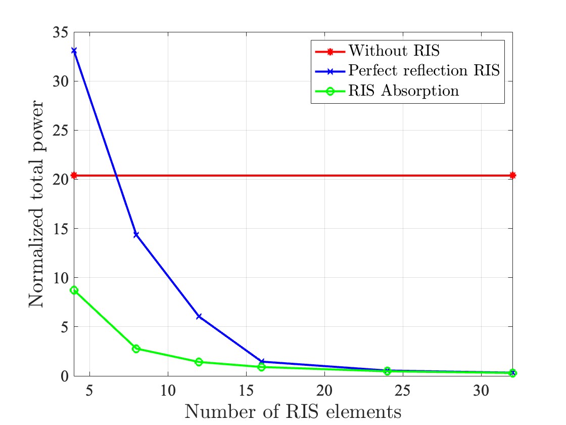
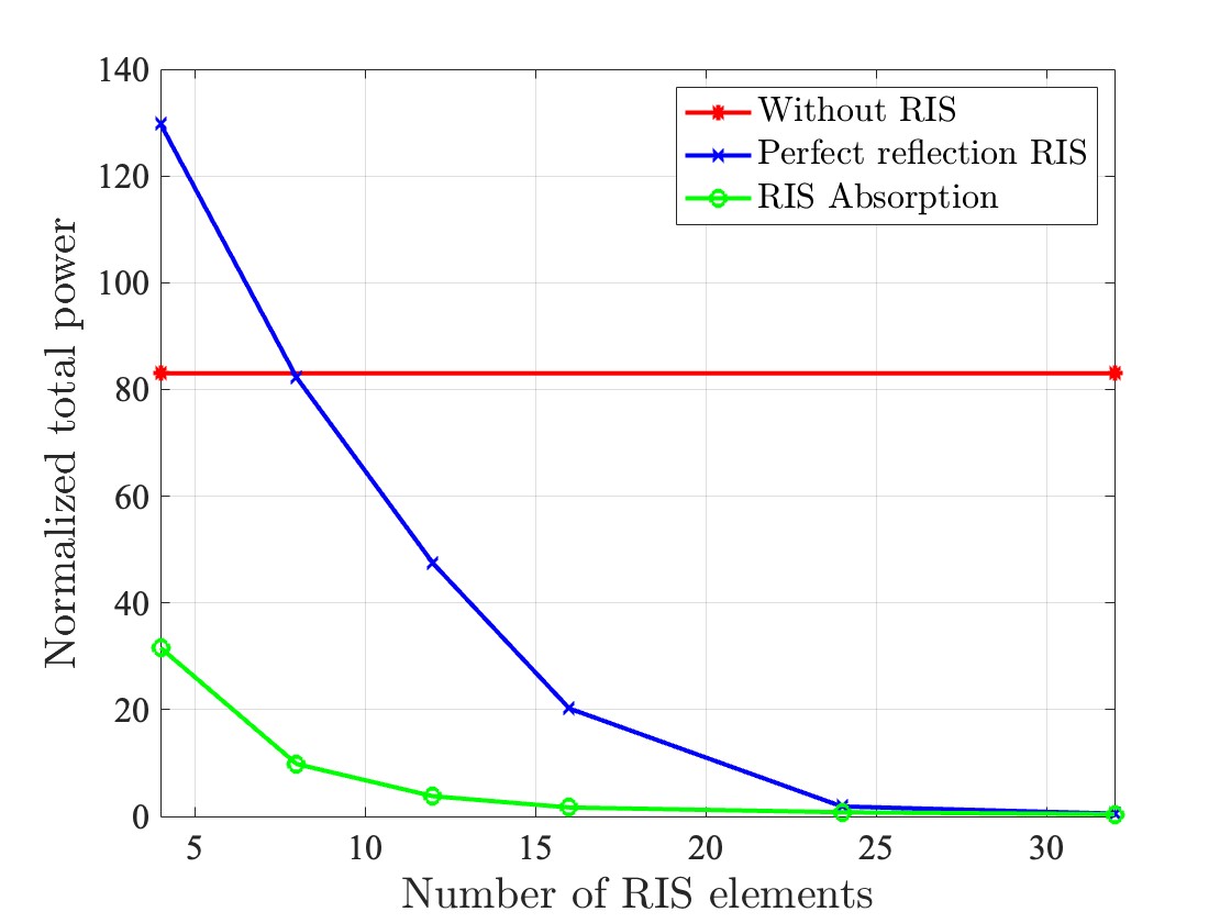
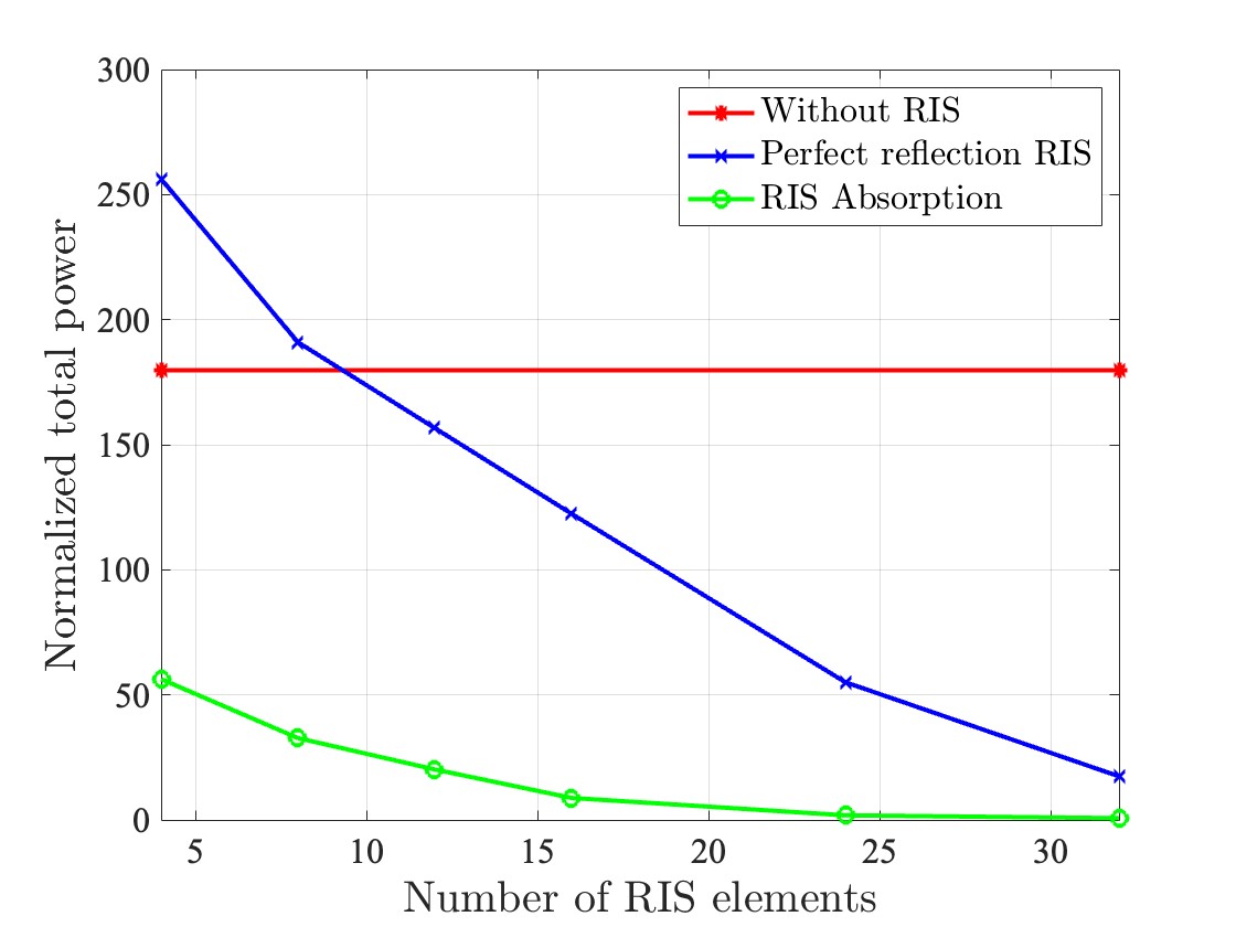
In Fig. 3(a), we show the resulting required total transmit power as a function of the number of RIS elements in the presence of a jammer with antennas. As can be seen, a regular non-absorbing RIS is beneficial compared with no RIS provided the RIS is equipped with more than elements, whereas the A-RIS has a performance gain for all considered . In Fig. 3(b) and Fig. 3(c), we show the corresponding results for a jammer with and elements, respectively. The relative performance for the no RIS, regular RIS, and A-RIS is the same, but due to the stronger jammer, the crossing point for the regular RIS increases with the number of jammer antennas . It is also interesting to note that, compared to the no RIS case, the required total transmit power more than doubles when the number of jammer antennas is increased from to , although the total jammer power is only doubled. That can likely be explained by the additional beamforming gain for the jammer. Increasing the number of jammer antennas from to , however, results in just slightly more than doubled required total transmit power, which can most likely be explained by saturation in the beamforming gain. Another interesting observation is that when the RIS is very small, e.g., with only 4 or 8 elements, the performance with a conventional phase-only RIS is actually worse than if no RIS were present at all. This is because the conventional RIS does not have a sufficient number of degrees of freedom to eliminate the interference, and its presence as a reflector only serves to actually increase the interference seen by the BS. The A-RIS is able to control the amount of reflected energy in addition to the phase shifts and thus does not suffer from this drawback.
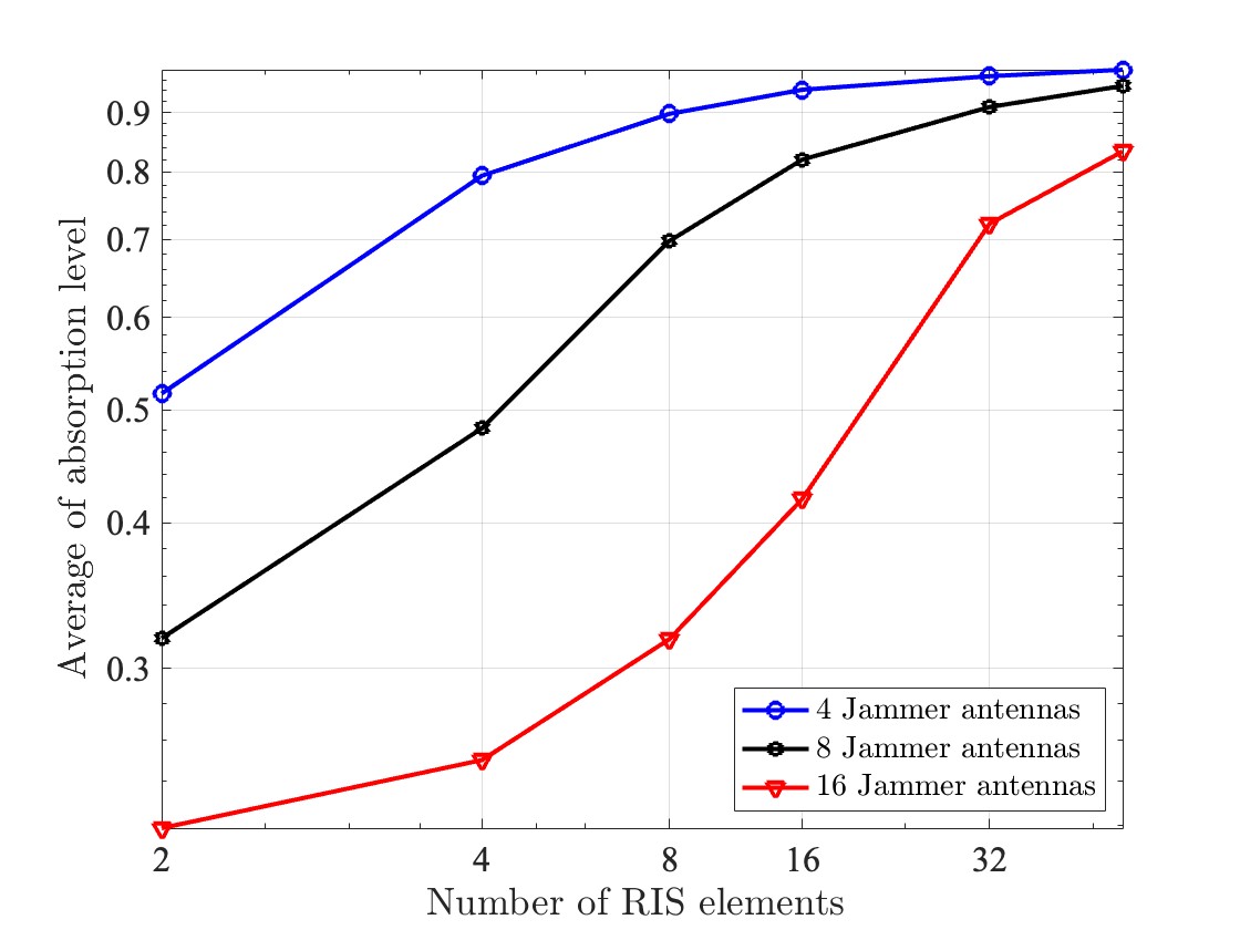
In Fig. 4, we show the resulting average absorption level of the A-RIS as a function of the number of A-RIS elements in the presence of a jammer with antennas. As can be seen, the absorption capability of the A-RIS is very useful when the degrees of freedom required for the A-RIS to mitigate the jammer is low, i.e. when the number of A-RIS elements is small compared to the number of jammer antennas . With increasing , the average absorption level of the A-RIS elements is monotonically decreasing, and thus the operation of the A-RIS approaches that of the regular non-absorbing RIS, which is in line with the results in Figs. 3(a)-3(c) showing that the performance of a conventional RIS is approaching the performance of the A-RIS as the number of elements increases.
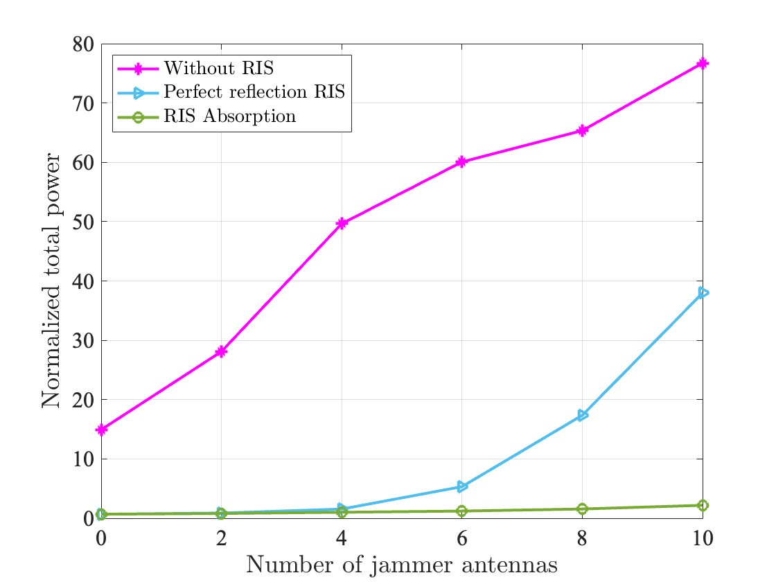
Finally, in Fig. 5, we show the total transmit power required to meet the user quality of service requirements as a function of the number of jammer antennas for the cases of no RIS, a conventional RIS, and an A-RIS, both with elements. As seen, the greater the number of jammer antennas, the more beneficial is the use of RIS technology, and the additional benefits of RIS absorption rapidly increase when the number of jammer antennas is more than .
V Conclusion
In this paper, we considered an uplink power-domain NOMA system assisted by an RIS in the presence of a smart jammer. We considered the performance of both a conventional RIS whose elements adjust only the phase of the incident signals, as well as an A-RIS that can adaptively adjust both the modulus and the phase of the elements. An optimization problem was formulated in which the goal is to minimize the total transmit power of the users under constraints on the SINR that the users achieve at the base station. Our simulation results demonstrate that both the conventional RIS and A-RIS provide dramatic reductions in required total transmit power due to their ability to enhance the signals of interest and cancel the effects of the interference. We also demonstrated that if the number of elements in the intelligent surface is small, the A-RIS can provide additional degrees of freedom that enable increased signal enhancement and interference mitigation.
Acknowledgment
This work has been supported by the project SEMANTIC, funded from EU’s Horizon 2020 research and innovation programme under the Marie Skłodowska-Curie grant agreement No 861165, as well as by the U.S. National Science Foundation under grants CNS-2107182 and ECCS-2030029.
References
- [1] Islam, SM Riazul, et al, ”Nonorthogonal multiple access (noma): How it meets 5g and beyond,” Wiley 5G Ref: The Essential 5G Reference Online, pp. 1-28, 2019.
- [2] Bana, Alexandru-Sabin, et al, ”Massive MIMO for Internet of things (IoT) connectivity,” Physical Communication, vol. 37, p. 100859, December 2019.
- [3] Xiao, H., et al, ”Resource management for multi-user-centric V2X communication in dynamic Virtual-Cell-Based ultra-dense networks,” IEEE Transactions on Communications, vol. 68, no. 10, pp. 6346-6358, 2020.
- [4] Sahoo, B.P., et al, ”Enabling millimeter-wave 5G networks for massive IoT applications: A closer look at the issues impacting millimeter-waves in consumer devices under the 5G framework,” IEEE Consumer Electronics Magazine, vol. 8, no. 1, pp. 49-54, 2018.
- [5] Di, B., et al, ”V2X meets NOMA: Non-orthogonal multiple access for 5G-enabled vehicular networks,” IEEE Wireless Communications, vol. 24, no. 6, pp. 14-21, 2017. capitalized,” J. Name Stand. Abbrev., in press.
- [6] L. Dai, B. Wang, Z. Ding, Z. Wang, S. Chen and L. Hanzo, ”A Survey of Non-Orthogonal Multiple Access for 5G,” in IEEE Communications Surveys & Tutorials, vol. 20, no. 3, pp. 2294-2323, 2018.
- [7] Islam, S.R., et al, ” Power-domain non-orthogonal multiple access (NOMA) in 5G systems: Potentials and challenges.,” IEEE Communications Surveys & Tutorials, vol. 19, no. 2, pp. 721-742, 2016.
- [8] Yang, G., Xu, X., Liang, Y. C., & Di Renzo, M. (2021). Reconfigurable intelligent surface-assisted non-orthogonal multiple access. IEEE Transactions on Wireless Communications, 20(5), 3137-3151.
- [9] Liu, Y., Liu, X., Mu, X., Hou, T., Xu, J., Di Renzo, M., & Al-Dhahir, N. (2021). Reconfigurable intelligent surfaces: Principles and opportunities. IEEE communications surveys & tutorials, 23(3), 1546-1577.
- [10] Sadia, H., M. Zeeshan, and S.A. Sheikh, ”Performance analysis of downlink power domain NOMA under fading channels,” in 2018 ELEKTRO, 2018.
- [11] Thomas M. Cover, Joy A, Elements of information theory, College of New York , 1991.
- [12] Islam, S., M. Zeng, and O.A. Dobre, ”NOMA in 5G systems: Exciting possibilities for enhancing spectral efficiency,” IEEE 5G Tech Focus, vol. 1, no. 2, June 2017.
- [13] Yuan, X., Zhang, Y. J. A., Shi, Y., Yan, W., & Liu, H. (2021). Reconfigurable-intelligent-surface empowered wireless communications: Challenges and opportunities. IEEE wireless communications, 28(2), 136-143.
- [14] Le, C. B., Do, D. T., Li, X., Huang, Y. F., Chen, H. C., & Voznak, M. (2021). Enabling NOMA in backscatter reconfigurable intelligent surfaces-aided systems. IEEE Access, 9, 33782-33795
- [15] Xiao, Liang, et al. ”Reinforcement learning-based NOMA power allocation in the presence of smart jamming.” IEEE Transactions on Vehicular Technology 67.4 (2017): 3377-3389.
- [16] Y. Liu, X. Mu, J. Xu, R. Schober, Y. Hao, H. V. Poor, and L. Hanzo, ”STAR: Simultaneous Transmission and Reflection for coverage by intelligent surfaces,” IEEE Wireless Communications, vol. 28, no. 6, pp. 102–109, 2021.
- [17] S. Zhang, H. Zhang, B. Di, Y. Tan, M. Di Renzo, Z. Han, H. Vincent Poor, and L. Song, “Intelligent Omni-Surfaces: Ubiquitous wireless transmission by reflective-refractive metasurfaces,” IEEE Transactions on Wireless Communications, vol. 21, no. 1, pp. 219–233, 2022.
- [18] X. Hu, R. Zhang, and C. Zhong, “Semi-passive elements assisted channel estimation for intelligent reflecting surface-aided communications,” IEEE Trans. Wireless Commun., vol. 21, no. 2, pp. 1132–1142, Feb. 2022.
- [19] H. Zhang, N. Shlezinger, I. Alamzadeh, G. C. Alexandropoulos, M. F. Imani, and Y. C. Eldar, “Channel estimation with simultaneous reflecting and sensing reconfigurable intelligent metasurfaces,” in 22nd International Workshop on Signal Processing Advances in Wireless Communications (SPAWC), 2021, pp. 536–540.
- [20] A. Albanese, F. Devoti, V. Sciancalepore, M. Di Renzo, and X. Costa-Perez, “MARISA: A self-configuring metasurfaces absorption and reflection solution towards 6G,” in IEEE International Conference on Computer Communications (INFOCOM), 2022, pp. 250–259.
- [21] I. Alamzadeh and M. F. Imani, “Sensing and reconfigurable reflection of electromagnetic waves from a metasurface with sparse sensing elements,” IEEE Access, vol. 10, pp. 105 954–105 965, 2022.