Efficient Multi-Cycle Folded Integer Multipliers
C. Emre Dedeagac
Abstract
Fast combinational multipliers with large bit widths can occupy significant silicon area. Provided the application allows for a multiplication to last two or more clock cycles, the area can be reduced through resource sharing (i.e., folding). This work introduces multiple architectures and parameterized Verilog circuit generators for Multi-Cycle folded Integer Multiplier (MCIM) designs, which are based on Schoolbook and Karatsuba approaches. When implementing an application in hardware, it is possible that a fractional number of multiplications is performed per cycle on average, such as 3.5. In such a case, we can use 3 single-cycle multipliers plus an additional smaller multiplier with a ThroughPut (TP) of 0.5. Our MCIM designs offer customization in terms of TP, latency, and clock frequency. The MCIM idea is for a TP of , where is an integer and . All proposed designs were synthesized and verified for various bit widths using scripts. ASIC synthesis results show that MCIM designs with a TP of 1/2 offer area savings of 21% to 48% for bit widths of 8 to 128, with respect to synthesizing the * operator. Additionally, MCIM designs can offer up to 33% energy savings and 84% average peak power reduction.
Index Terms:
Multi-cycle multiplier, folded multiplier, unsigned integer multiplication, Karatsuba multiplier, computer arithmetic.I Introduction
Integer multipliers are essential building blocks for various ASICs and CPUs. Large integers are used in a wide range of applications, which require high degrees of precision. A 128-bit integer data type was introduced into CUDA [1] in 2021 due to its importance. Multiplying such large integers (hence large bit widths) can get quite expensive in terms of silicon area. For this reason, lowering the area complexity of integer multipliers can be very beneficial. This work addresses unsigned integer multiplication. However, our proposed designs can easily be extended to handle signed integer multiplications.
There are applications that require the execution of multiplication operations every two or more cycles. Such a case is found in low-cost microcontrollers, where area efficiency is vital, even if it comes at the expense of increasing the latency of multiplication.
Applications can contain numerous multiplications in their data flow paths. Due to the area complexity of these multipliers, the same multiplication circuits are used over and over again to minimize the area complexity of the system. ASIC blocks usually implement algorithms that are repeated indefinitely, each time lasting a fixed number of clock cycles (a.k.a., cycle-time). The number of multipliers required in such an algorithm can be calculated by dividing the number of multiplications by the Cycle-Time (CT), a.k.a., Initiation Interval.
The above assumes a use case where there are no critical inter-iteration dependencies, and hence, the multiplications can be equally spread over the cycles of a CT. The number of multiplications per cycle, hence the number of multipliers required is not always an integer number. The conventional approach is to round up this value, which causes one of these multipliers to be underutilized.
This work presents area-efficient Multi-Cycle folded Integer Multipliers (MCIMs). These designs can replace underutilized single-cycle multipliers, thereby offering area savings.
There is also a use case where multiple multipliers are used in parallel while being underutilized. Reusing a single multiplier for multiple operations increases the latency, which is not an option if there are latency constraints. This can be due to inter-iteration dependencies or other application requirements. MCIM designs can be utilized in such cases to offer area savings without violating the latency constraints. The use cases will be discussed in more detail in Subsection V-E.
Multi-cycle multipliers following a divide and conquer approach can implement several levels of recursion, successively decreasing the size of the multiplier. The CT defines the number of times the same hardware can be reused, which is also known as the initiation interval. The CT is the minimum period between consecutive inputs. The ThroughPut (TP) can be calculated as and hence has a unit of .
The rest of the paper is organized as follows. Section II presents the previous work. Section III presents the architectures proposed in this work. Section IV describes the methodology used for design generation, synthesis, and verification. Section V presents the implementation results, while Section VI concludes the paper.
II Previous Work
Whether a multiplier is multi-cycle or single-cycle, its underlying algorithm should be efficient to start with. In [2], C. S. Wallace came up with the carry-save approach for the compression of a sum of 3 or more numbers into 2 numbers. He reduced the time complexity (i.e., the critical path) of multiplication from to . In [3], Dadda presented an improvement over Wallace’s method. This reduced the number of Full Adder and Half Adder cells in some cases. Ugurdag et al. in [4] proposed an efficient carry-save tree structure called Row and Column Compression trees (RoCoCo). This work was later improved on for FPGA targets in [5]. RoCoCo results in a narrower bit width, hence faster Final Adder, which follows the carry-save tree. Considering how RoCoCo can offer improvements over Wallace [2] and Dadda [3] trees, it is also utilized in this work.
As for multi-cycle multipliers and/or large bit widths, a divide and conquer strategy can be used to split a multiplication into smaller multiplications or smaller reusable blocks. Given multiple cycles, these smaller multiplications/blocks can share hardware resources in order to reduce the total hardware area. Any efficient multiplication technique can be at least employed within the reusable small multiplier of a multi-cycle multiplier.
The conventional Schoolbook approach divides a multiplication into multiple smaller parts using the distributive property. Equations 1 and 2 show how a single multiplication can be divided into two or three smaller multiplications using the Schoolbook approach, where N is the bit width of the second multiplicand B.
| (1) |
| (2) |
Such an approach can be utilized for area reduction, where a smaller multiplier is used repeatedly to compute several smaller multiplications (i.e., resource sharing). For CTs that are , it is possible to chop both variables into smaller parts. However, that would increase the critical path without offering additional area savings. In our approach, we only divide one variable into as many parts as CT.
II-A Multi-cycle Multipliers
Multiple works have evaluated multi-cycle multipliers in the past, both for FPGA and ASIC applications. However, most of these works provide multipliers with long latencies and very low TPs. This limits the usability of these in various applications where timing is critical. The authors in [6] extensively studied the topic of large integer multiplication, with a focus on FPGA implementation. They proposed several architectures involving Schoolbook multiplication, Comba multiplication, Karatsuba multiplication, and Number Theoretic Transforms. These architectures are suited for different applications, each having different characteristics. In their architectures, the latency depends on the bit widths of the multiplicands, thus utilizing more resource sharing for large multipliers. Their architectures can only handle a single multiplication at a time, which significantly limits the TP. The latencies of their designs for a 128128 multiplier range from 10 to 4400 cycles, depending on the specific architecture.
In [7], a design implementing the Karatsuba algorithm was proposed. Due to the recursive nature of the Karatsuba Algorithm, they proposed the use of a “Coprocessor,” which was responsible for the sub-functions of the Karatsuba algorithm, such as multiplication, addition, and shifting operations, where the “Coprocessor” has a fixed size. A Block RAM was used to store the intermediate results. Using this approach, they were able to produce a multiplier that could compute multiplications with different bit widths using the same area resources. However, this approach produces very high latencies as the multiplication size increases, requiring 120 cycles to implement a 128128 multiplication. Furthermore, this approach significantly limits the TP since the design can only handle a single multiplication at a time. Their architecture further improved upon other FPGA-based MC multipliers proposed in [8, 9], and [10]. The authors in [11] proposed a design based also based on Karatsuba multiplication; their design achieves significant area reduction for FPGAs, requiring 1/9th of the DSP resources for a conventional 20482048 multiplication. For a 20482048 multiplication, they achieve a latency of 118 cycles and a CT of 9 cycles. However, this design is only feasible for very large multiplications with a more limited number of applications. Kumm et. al. proposed a Karatsuba-based architecture in [12] to improve FPGA-resource utilization for multiplications larger than 64 bits. They propose a modified Karatsuba approach that uses the fixed bit widths of DSP slices as design parameters. Due to this approach, their designs are not useful when targeting ASIC applications, as they themselves mention. The latency of their designs are dependent on a multiplication’s bit width, where larger multiplications increase the latency. Li et al. presented a multi-cycle multiplier in [13] that is similar to a shift and add multiplier. Their designs offer a TP of for an multiplication and a latency of N+1 cycles. All these designs have long latencies and low TPs; therefore, they target a different segment of applications than that of this work.
In [14], an iterative multiplication circuit for 6464 was proposed, having a TP of 1/4 and a latency of 10 cycles. Their design uses an internally generated clock through the usage of NOT gates. The clock generation circuitry requires manual modification to work with different system clocks. Such an approach limits the design’s scalability and usability. Another design was proposed in [15] that implements a multi-cycle multiplication circuit. They use self-timed clocks that do not require manual modification to change the operating frequency, allowing them to work with any system clock. Their architecture offered an area reduction of 86.6% in comparison with an array implementation, coming at the cost of an 18.8% reduction in speed. However, this architecture is considered a combinational circuit with respect to the system clock since the multi-cycle path is expected to be executed within 1 system clock cycle. Thus, the system clock is limited by the maximum frequency of the design.
Molina et al. presented a design technique in [16] that allows for resource sharing in multi-cycle operators. Their technique can be applied as an optimization step at the end of a high-level synthesis process. They present an example of a 2-cycle array multiplier of size 12864. This multiplier can be implemented using one multiplier of size 6464 and two smaller 3264 multipliers. They spread the 6464 multiplier over two cycles by separating it into two parts: “Tup” and “Tdown”, which improves the critical path of the design. Using their techniques, they can apply resource sharing and only require a single 32 64 multiplier, offering an area reduction of 30%. The scheduling for their proposed multiplier can be described by Table IX.
| cycle 0 | cycle 1 | |
|---|---|---|
| 3232 | ||
| Tup | - | |
| TDown | - |
Array multipliers are inefficient in terms of area complexity. Thus, our designs can offer significantly more area reduction with respect to integer multiplications.
II-B Karatsuba Multiplier
Karatsuba’s [17] was one of the first algorithms proposed to reduce the complexity of integer multiplication. Reduction in algorithmic complexity can be exploited to reduce hardware area.
In a conventional divide and conquer approach, i.e., the Schoolbook approach, the total complexity (i.e., number of operations) for an integer multiplication is . Karatsuba [17] proposed an algorithm that decreases the complexity to . The Karatsuba algorithm can be described by equations 3,4, 5, and 6 for a single level of division, where the number of smaller multiplications required is reduced from 4 to 3.
| (3) |
| (4) |
| (5) |
| (6) |
The Karatsuba algorithm can be implemented on hardware for a reduction in area complexity, as previously shown in [6, 7], and many others. The 3 smaller multiplications required for a single level of recursion using the Karatsuba approach can be computed using the same hardware, therefore reducing the area complexity. The Karatsuba approach is best suited for large multiplications.
III Proposed Architectures
Multiplication can be represented as a sum of several smaller multiplications using either the Schoolbook or Karatsuba approach. If the desired TP is 1, the same hardware can be used to compute the smaller multiplications, which is known as “resource sharing”. This can significantly reduce the area complexity of a multiplier. Using regular (single-cycle) multipliers for these smaller multiplications is not very efficient since it will result in a quite longer critical path. A better approach is to use Partial Product Multipliers (PPMs) for these smaller multiplications. PPMs are multipliers that omit the final addition (producing two results). Using a multi-cycle approach, there will be variables that need to be summed for each small multiplication. When resource sharing is applied, using PPMs instead of regular multipliers is more efficient since it allows for a compressor (carry save tree without the final addition) to be used before the final addition.
III-A Building Blocks
Our architectures consist of three core sub-modules: PPM, compressor, and final adder. Several architectures for these submodules were used in this work, each having certain advantages. These submodules are used as building blocks for our designs, creating multiple possible variations for the overall architecture.
DW02_multp is a synthesis-based PPM offered by Synopsys [18], which can produce fast and area-efficient PPMs. Similarly, DW02_tree is a synthesis-based compression tree also offered by Synopsys [18], which can provide fast and area-efficient compressors.
RoCoCo, proposed in [4], presents a row and column compression tree that can be used to create fast and area-efficient integer multipliers and compressors. RoCoCo can provide both PPMs and compressors. RoCoCo maximizes the bit reduction made, where several of the least significant bits of the second output are reduced to 0. This reduces required computations in the following stages, often reducing the overall area complexity.
A custom area-efficient compression tree is proposed in this work as well. This compression tree aims at minimizing the area resources. This compressor is tailored for a feed-forward architecture (which will be discussed in Subsection III-C) utilizing a DW02_multp PPM. Since this compressor is designed to minimize the required hardware resources, it does not achieve identical bit reductions as RoCoCo. This approach can be helpful since the final addition can be spread into multiple cycles through the use of resource sharing or pipelining.
The last stage of our designs is the final adder, which handles the addition of the results produced by the compressor. Multiple designs were implemented and tested for the final adder. A standard 1-cycle adder (1CA) is usually the optimal choice for our designs (which is inferred using a “+” symbol) since it can easily be pipelined. A 2-cycle resource shared adder was implemented. This adder creates a feedback loop around a series of full adder cells reducing the area requirements. However, it was always outperformed by other designs when complete designs were synthesized. The feedback loop limits the critical path and makes it difficult to pipeline the design. A pipelined version of the 2-cycle adder was also implemented to meet strict timing targets, but it increased the area complexity to an undesirable point. Lastly, a 3-Cycle resource shared Adder (3CA) was also implemented. This adder utilizes a feedback loop to reduce the resources required for the addition by up to 66%. 3CA is only usable by designs with a TP , but it often provides additional area savings.
Three architectures are proposed in this work using the previously discussed sub-modules, each having different variations in the sub-modules used. These designs are optimized for specific applications in terms of the target frequency and multiplication sizes, maximizing the area reductions that can be achieved.
III-B Feedback Architecture
This architecture is based on the Schoolbook approach and can be described by equations (1) and (2) for a CT of 2 and 3. For CTs 4, it is possible to separate both multiplicands into smaller parts. However, separating only one variable maintains a lower critical path with no significant effect on the area complexity. In this architecture, all three multiplier stages are resource-shared, which are the PPM, the compressor, and the final adder. These stages are fully utilized under regular operation (when inputs arrive back to back). This is achieved by creating a feedback loop around the compressor and final adder, reducing the bit width of both.
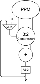
For an multiplication, this architecture uses an PPM and an final adder and 3:2 compressor. The PPM computes all the smaller multiplications. The compressor and final adder sum the results of the PPM and the shifted version of the previous result (which is 0 in the cycle). The least significant bits of the final adder’s result are stored in registers since they are part of the final result. In the last cycle, the final result is a concatenation of the output of the final adder and the values stored in the registers. This design is represented by Fig. 1. Since the final adder is included in a feedback loop, only 1CA can be used. This approach uses the least amount of resources out of our designs. However, it can be outperformed by our other designs for strict timing targets, where the feedback loop can be a limiting factor.
III-C Feed-forward Architecture
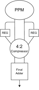
Multipliers are frequently used with high-frequency applications; thus, short critical paths can be very beneficial. The critical path limits the maximum frequency and affects the area complexity. A circuit synthesized using its maximum frequency consumes significantly more area than one synthesized for a relaxed frequency. When operating under strict timing conditions, the synthesis tool instantiates larger library cells with shorter delays to meet timing. In contrast, the synthesis tool can use small library cells with longer propagation delays when dealing with relaxed timing targets. The critical path is caused by the combinational circuit that has to be executed within the same cycle. The critical path is reduced when this combinational logic is divided across multiple cycles. Thus, both speed and area would improve. Having a feedback loop in the design limits the design’s ability to be pipelined. For this reason, we propose a design that contains no feedback loops, allowing it to be pipelined to meet very strict timing targets. This architecture is based on the Schoolbook approach. It first computes all the partial product multiplications using the PPM, storing the results in registers, and then sums the results using the compressor and final adder (while shifting accordingly). This architecture is represented by Fig. 2. Such an architecture, however, is only area-efficient for a CT of 2 (TP of 1/2) because the area complexity increases as CT is further increased. The compressor would have to handle more reductions, and more registers are required to hold the intermediate registers. Thus, the overall area complexity increases as CT is increased beyond 2. For an multiplication and a CT of 2, this design uses an PPM, and an 4:2 compressor and final adder.
III-D Karatsuba Architecture
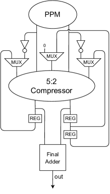
The Karatsuba approach is commonly used to create area-efficient multipliers. Using the Karatsuba approach for our designs allows us to require a much smaller PPM with respect to a Schoolbook approach with the same CT. Fig. 3 represents a Karatsuba design with a CT of 3. This architecture uses a small feedback loop around the compressor, which reduces the compressor’s depth and does not require registers to store intermediate values. For an MN multiplier, this architecture uses an PPM, and an final adder and 5:2 compressor.
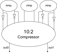
The addition and subtraction operations from the Karatsuba approach are handled by the compressor. Two’s complement is applied for the subtractions by applying a NOT-gate to all the bits and then incrementing the result (which is added using the compressor). Multiple levels of recursion can be applied. We implemented a Karatsuba PPM, which can be described in Fig. 4. This PPM allows us to implement multiple levels of division in a recursive fashion without affecting the latency and TP of the multiplier. The Karatsuba-based PPM is created using three smaller PPMs and a 10:2 compressor. This PPM is efficient for large multiplications. Thus, large multiplications can benefit from greater levels of recursion.
The Feed-Forward and Karatsuba architectures compute the Final Addition separately. Omitting the final addition from these designs presents a new multi-cycle PPM. Multi-cycle PPM can be applied to the Karatsuba and feed-forward architectures in a recursive fashion to achieve TPs that are factors of 2 and 3. However, this approach is not optimal since it increases the design complexity, limiting the area reductions that can be achieved.
IV Implementation
The proposed designs were tested thoroughly, using different bit widths, latencies, and timing targets. This required several steps, including design generation, synthesis, pipelining, simulation, and power reporting. These steps were automated using a series of scripts that handle these tasks accordingly. This automation allows for a greater degree of testing that is required for a complete evaluation of all the proposed designs. The designs are generated using RTL generation scripts written in Python, synthesized using the Synopsys Design Compiler and a TSMC 40 nm technology, and simulated using Synopsys VCS.
In this work, three main architectures are proposed, which can have variations in the TP and type of compressor, PPM, and final adder. Due to this, design generation scripts were used to accommodate these variations easily. All designs are instantiated with a wrapper, which automatically sets the input/output delays and loads. The wrapper applies a register to each of the inputs and outputs of the design except the clock signal. There are three different generators for MCIM designs, one for each architecture. All the generators create both a wrapper and a testbench, allowing for easy and accurate testing for each design.
Retiming is a technique used to optimize digital circuits by moving flip-flops. It can significantly reduce the critical path and improve the area. Since strict timing targets require larger library cells, reducing the critical path can also decrease the area complexity. The Synopsys Design Compiler offers the retiming feature, which is utilized to achieve optimized pipelining in this work automatically. To increase the depth of the pipeline, registers are added at the end of the design, which is handled by the design generators. The synthesis tool can freely move these registers as long as they do not affect a feedback loop in the design. Increasing the pipeline’s depth also increases the latency, but it can reduce both the area complexity and the critical path while maintaining the same TP.
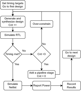
Synthesis is not a linear computation. It has to handle various constraints to meet timing, optimize area, and minimize power consumption. Over-constraining is another technique to meet strict timing targets when the synthesis tool fails to meet timing. This is done by further restricting the timing target, allowing the synthesis tool to make decisions that expect a more strict timing target. This can often allow our designs to meet the required timing target even if the initial synthesis attempt fails to meet timing. Over-constraining is applied by reducing the timing target by 5% and re-attempting synthesis. Over-constraining is attempted three times by the automation scripts before increasing the depth of the pipeline (adding registers to the design and applying retiming).
The synthesis results of all MCIM designs and the standard multiplier generated by Synopsys using the * operator (which will be referred to as Star) are compared. The traditional approach is to set the design parameters, such as the CT and latency, and synthesize a design using the best achievable frequency. However, this approach is not the best representation of the results since the target frequency is usually a design decision or constraint. The area complexity, power consumption, and operating frequency are all interdependent. Thus, the timing target selection significantly affects the results. For this reason, we select the timing target first and then update a design’s latency (pipeline depth) to meet the target timing. The same timing targets are used when comparing different designs.
The initial timing target is set as the maximum frequency achieved by the Star multiplier without adding any additional pipeline stages. Additionally, over-constraining is used to test if a higher maximum frequency can be achieved. Timing is then increased by 15% and 30% to see how the designs perform in more relaxed timing conditions. Lastly, we include two more timing targets to see how these designs perform in very strict and relaxed timing conditions. The strict target is set as a target that cannot be achieved by any design without pipelining. This demonstrates how well these designs can be pipelined. The relaxed timing condition is set as a target that can be met by all the designs with no pipelining. After setting the timing targets, the automation script synthesizes and tests all the designs and reports the results. Additionally, the pipeline depth affects the critical path, which also affects the area complexity. Therefore, all the designs are synthesized with additional pipeline stages until the latency reaches the maximum latency of other designs. The automation script can be described in Fig. 5.
All the designs are simulated using a set of 200 randomly generated inputs using the SDF file generated from synthesis. Self-checking test benches were used, where the output is sampled depending on the latency of the design. The power consumption is analyzed using the Synopsys Design Compiler. It loads the SAIF file generated from the netlist simulation and the previously generated netlist.
V Results
All the proposed designs were tested thoroughly. Each design has advantages under certain conditions, which can maximize the area savings that can be offered by MCIM designs for a given application. The designs were synthesized under a wide range of multiplication sizes and various timing targets. This section will present four tables that can represent strict and relaxed timing conditions for both a small and a large multiplication. The unit for energy (Ener.) can be calculated by multiplying power by CT, which is represented as uWc or mWc in the tables, where c is the unit of time in terms of cycles. This work targets low CTs. Thus the tables presented in Sections V-A and V-B focus on designs with CTs = 2 and 3.
V-A Synthesis Under Relaxed Timing Conditions
Using a relaxed timing target presents the area complexity of each design without being affected by the critical path. The relaxed timing conditions case is represented by a timing target of 10 ns. Such a target allowed all the designs to meet timing without requiring additional pipeline stages while being able to use small library cells. Additional pipeline stages are not required since the timing target is very relaxed. Thus, the latency presented in tables II and III represents these designs’ minimum latency (L). Table II presents the synthesis results of 1616 bit multipliers.
Under Relaxed Timing Conditions (Target = 10 )
| Design | CT | PPM | Comp. | L | Area | Power | Ener. |
|---|---|---|---|---|---|---|---|
| (uW) | (uWc) | ||||||
| Star | 1 | - | - | 1 | 1348 | 170 | 170 |
| FB | 2 | DW02 | FAs | 2 | 942 | 105 | 210 |
| 2 | RoCoCo | FAs | 2 | 960 | 109 | 218 | |
| 3 | DW02 | FAs | 3 | 748 | 78 | 234 | |
| 3 | RoCoCo | FAs | 3 | 757 | 80 | 240 | |
| FF | 2 | DW02 | DW02 | 2 | 1096 | 113 | 226 |
| 2 | DW02 | RoCoCo | 2 | 1145 | 117 | 234 | |
| 2 | DW02 | Custom | 2 | 1105 | 113 | 226 | |
| 2 | RoCoCo | DW02 | 2 | 1051 | 110 | 220 | |
| 2 | RoCoCo | RoCoCo | 2 | 1122 | 112 | 224 |
Karatsuba designs favor larger multiplications and do not provide area savings for small multiplications; therefore, they are omitted from Table II. The FeedBack (FB) designs best suit applications that do not require very strict timing targets. The FB designs can offer around 30% area savings for a TP of 1/2 and around 45% for a TP of 1/3 for the conditions presented in Table II. Although Star consumes less energy in this case, it has a much higher average peak power, which is the average power consumed when inputs arrive back to back. Peak power is an important consideration since it affects the required power supply and thermal performance. Star almost always has a higher average peak power than our designs, which is expected since it can compute a multiplication in every clock cycle.
Area reductions are much more significant for large multipliers due to their large area complexities. The Karatsuba MCIMs were specifically designed for large multiplications. Thus, they have an advantage when it comes to large multiplications. Single-cycle Karatsuba multipliers save area for only very large multiplications (as large as 512512 bits). Such plain integer multiplications (non-crypto) have a limited number of applications. Using a multi-cycle approach, the size at which Karatsuba multipliers become area-efficient becomes much smaller, increasing the number of applications where they can be utilized. The proposed multi-cycle Karatsuba multipliers can offer area savings with respect to Star for any multiplication of size 3232 and greater. However, when compared to our other MCIM designs, Karastuba designs only offer an advantage for multiplications of size 128x128 and greater. The synthesis results of 128128 bit multipliers under relaxed timing targets are presented in Table III.
Under Relaxed Timing Conditions (Target = 10 )
| Design | CT | PPM | Comp. | FA | L | Area | Pow. | Ener. |
|---|---|---|---|---|---|---|---|---|
| (mW) | (mWc) | |||||||
| Star | 1 | - | - | - | 1 | 66319 | 11.38 | 11.38 |
| FF | 2 | RoCoCo | DW02 | 1CA | 2 | 59250 | 4.20 | 8.4 |
| 2 | RoCoCo | RoCoCo | 1CA | 2 | 59774 | 3.89 | 7.78 | |
| 2 | DW02 | DW02 | 1CA | 2 | 37042 | 4.62 | 9.24 | |
| 2 | DW02 | Custom | 1CA | 2 | 37790 | 6.15 | 12.3 | |
| 2 | DW02 | RoCoCo | 1CA | 2 | 38248 | 4.36 | 8.72 | |
| FB | 2 | DW02 | FAs | 1CA | 2 | 42913 | 4.03 | 8.06 |
| 2 | RoCoCo | FAs | 1CA | 2 | 57971 | 3.82 | 7.64 | |
| 3 | DW02 | FAs | 1CA | 2 | 30217 | 3.36 | 10.08 | |
| 3 | RoCoCo | FAs | 1CA | 2 | 38610 | 4.05 | 12.15 | |
| Karat-1 | 3 | DW02 | DW02 | 1CA | 3 | 31743 | 4.25 | 12.75 |
| 3 | DW02 | DW02 | 3CA | 5 | 27929 | 4.38 | 13.14 | |
| Karat-2 | 3 | DW02 | DW02 | 1CA | 3 | 27913 | 4.23 | 12.69 |
| 3 | DW02 | DW02 | 3CA | 5 | 27463 | 5.21 | 15.63 | |
| Karat-3 | 3 | DW02 | DW02 | 1CA | 3 | 30040 | 4.56 | 13.68 |
| 3 | DW02 | DW02 | 3CA | 5 | 29657 | 6.64 | 19.92 |
The Karatsuba architecture can be applied with several levels of recursion. The optimal level of precision is dependent on the multiplication bit width as well as the timing target. Large multiplications can benefit from additional levels of recursion. For the case presented in Table III, 2 levels of recursion can provide the most area savings. Karatsuba designs are represented as Karat-K in the tables, where K is the levels of recursion applied. The Karatsuba design consumed the least area of these designs, offering area savings of up to 58%. Karatsuba designs are affected positively by increasing the multiplication bit width, providing greater area savings. The feed-forward design is very efficient as well, offering area savings of 44% and energy savings of 32%.
V-B Synthesis Under Strict Timing Conditions
An essential aspect of ASICs is their ability to operate at high frequencies. All MCIM designs were tested using strict timing conditions to demonstrate their ability to offer area savings for high-speed applications. The designs are tested using a timing target that cannot be met without pipelining. For 1616 multiplications, this is set as 0.31 ns, which is equal to the clock-to-q + setup + hold delay for 1 FA placed between registers. Table IV presents the synthesis results under such conditions.
Using Strict Timing Conditions (Target = 0.31 )
| Design | CT | PPM | Comp. | L | Area | Timing | Pow. | Ener. |
|---|---|---|---|---|---|---|---|---|
| (ns) | (mW) | (mWc) | ||||||
| Star | - | - | - | 7 | 5178 | 0.31 | 13.34 | 13.34 |
| FF | 2 | RoCoCo | DW02 | 9 | 3963 | 0.31 | 6.58 | 13.16 |
| 2 | DW02 | DW02 | 9 | 3984 | 0.31 | 6.76 | 13.52 | |
| 2 | RoCoCo | RoCoCo | 7 | 4065 | 0.31 | 6.52 | 13.04 | |
| 2 | DW02 | Custom | 9 | 4065 | 0.31 | 7.18 | 14.36 | |
| 2 | DW02 | RoCoCo | 9 | 4200 | 0.31 | 7.25 | 14.5 | |
| FB | 2 | DW02 | FAs | 4 | 3712 | 0.46 | 6.58 | 13.16 |
| 2 | RoCoCo | FAs | 6 | 3554 | 0.49 | 5.78 | 11.54 | |
| 3 | DW02 | FAs | 9 | 3625 | 0.46 | 6.14 | 18.42 | |
| 3 | RoCoCo | FAs | 9 | 3096 | 0.44 | 5.07 | 15.21 |
The feedback (FB) designs are not able to meet the timing target in Table IV, due to the feedback loop. The Karatsuba designs are not suited for such small multiplications. Thus, they are not included in the table. Under these conditions, the feed-forward (FF) designs are the best option, offering up to 23% area savings.
Larger multipliers have longer critical paths. Very strict timing targets such as the one used for Table IV (0.31 ns) is only achievable by feed-forward designs for large multiplications. A more appropriate representation for strict timing conditions is to test the designs them using their maximum frequency. Assuming there are no latency constraints, the maximum frequency is only relevant for designs that cannot be pipelined. Table V presents the maximum frequency that can be achieved by MCIM designs with 6 pipeline stages. The Star and the feed-forward designs can be continuously pipelined to meet very strict timing targets, and therefore they are not included in this table. The designs were synthesized using an impossible target frequency of 0 and using 6 pipeline stages. The area and power results are not included since these achieve different frequencies, which directly affect the area and power consumption.
| Design | CT | PPM | Comp. | FA | L | Timing |
|---|---|---|---|---|---|---|
| FB | 2 | DW02 | FAs | 1CA | 8 | 0.8 |
| 2 | RoCoCo | FAs | 1CA | 8 | 0.78 | |
| 3 | DW02 | FAs | 1CA | 9 | 0.76 | |
| 3 | RoCoCo | FAs | 1CA | 9 | 0.77 | |
| Karat (1) | 3 | DW02 | DW02 | 1CA | 9 | 0.54 |
| 3 | DW02 | DW02 | 3CA | 11 | 0.76 | |
| Karat (2) | 3 | DW02 | DW02 | 1CA | 9 | 0.59 |
| 3 | DW02 | DW02 | 3CA | 11 | 0.74 | |
| Karat (3) | 3 | DW02 | DW02 | 1CA | 9 | 0.65 |
| 3 | DW02 | DW02 | 3CA | 11 | 0.8 |
All the designs are capable of meeting a clock target of 0.8 ns for 128128 multiplications as seen in Table V. Thus, this timing target is used in the strict timing conditions for large multiplications. The synthesis results for these conditions are presented in Table VI.
Using Strict Timing Conditions (Target = 0.8 )
| Design | CT | Comp. | FA | L | Area | Power | Energy |
|---|---|---|---|---|---|---|---|
| (mW) | (mWc) | ||||||
| Star | 1 | - | - | 4 | 121634 | 98.14 | 98.14 |
| FF | 2 | DW02 | 1CA | 4 | 67884 | 33.01 | 66.02 |
| 2 | Custom | 1CA | 4 | 64778 | 31.83 | 63.66 | |
| FB | 2 | FAs | 1CA | 4 | 92240 | 47.47 | 94.94 |
| 3 | FAs | 1CA | 6 | 48068 | 30.45 | 91.35 | |
| Karat-1 | 3 | DW02 | 1CA | 7 | 44888 | 26.95 | 80.85 |
| 3 | DW02 | 3CA | 7 | 57568 | 34.26 | 102.78 | |
| Karat-2 | 3 | DW02 | 1CA | 7 | 47604 | 28.18 | 84.54 |
| 3 | DW02 | 3CA | 7 | 53838 | 36.57 | 109.71 |
For the conditions in Table VI, designs using a RoCoCo compressor/PPM increase the area to an undesirable degree where the designs no longer offer area savings. This shows that the RoCoCo compressor and PPM do not scale very well for large multiplications, increasing the area complexity to an undesirable degree where they offer no area savings. Therefore, designs using RoCoCo PPMs and compressors are omitted from Table VI. Only the DW02 PPM is used for all the designs in the table.
Karatsuba designs are the most efficient multipliers for the conditions in Table VI. They offer the most area savings using 1 level of recursion. The 3CA final adder is not suitable for strict timing conditions due to the feedback loop, which increases the area complexity for such cases. The Karatsuba designs offer area savings of 63% as well as energy savings of 18%. The feed-forward design that uses the DW02 PPM and the Custom compressor offers area savings of 47% and power savings of 33%. When MCIM designs offer such savings, even utilizing two 3-cycle designs becomes viable; such a combination can achieve a TP of 2/3 while offering an area saving of up to 26%. Additionally, a combination of one 2-cycle multiplier and one 3-cycle is also viable, offering a combined TP of 5/6 and an area saving of up to 9%. Depending on the application’s requirements, which include energy consumption, area limitation, and TP requirement, any of these designs or a combination of these designs can be the optimal choice.
V-C Results for Other CTs
The architectures presented in this work are suitable for any CT. However, the feedback design is the most appropriate design of our architectures for CT 3. The feed-forward design is only area-efficient for a CT of 2 since increasing the CT impacts the area negatively. The Karatsuba algorithm gives optimal results for a CT of 3. However, it can be implemented for any CT that is a multiple of 3. This, nevertheless, is only beneficial for very large multiplications. The feedback design scales well as CT increases, offering an increase in area savings. Table VII includes the synthesis results of 32 32 bit multipliers using different CTs (2-8). Feedback designs scale well for greater CTs, offering greater area reductions and reducing the average peak power.
with CTs up to 8 (target = 10 )
| Design | CT | PPM | Area | Area | Power | Energy |
|---|---|---|---|---|---|---|
| Savings | (mW) | (mWc) | ||||
| Star | 1 | - | 4349 | - | 0.74 | - |
| FB | 2 | DW02 | 2624 | 40% | 0.46 | 0.92 |
| RoCoCo | 3469 | 20% | 0.39 | 0.76 | ||
| 3 | DW02 | 2188 | 50% | 0.29 | 0.87 | |
| RoCoCo | 2470 | 43% | 0.25 | 0.75 | ||
| 4 | DW02 | 1876 | 57% | 0.23 | 0.92 | |
| RoCoCo | 1949 | 55% | 0.21 | 0.84 | ||
| 5 | DW02 | 1739 | 60% | 0.17 | 0.85 | |
| RoCoCo | 1750 | 60% | 0.16 | 0.80 | ||
| 6 | DW02 | 1567 | 64% | 0.15 | 0.90 | |
| RoCoCo | 1572 | 64% | 0.14 | 0.84 | ||
| 7 | DW02 | 1385 | 68% | 0.14 | 0.98 | |
| RoCoCo | 1389 | 68% | 0.13 | 0.91 | ||
| 8 | DW02 | 1206 | 72% | 0.12 | 0.96 | |
| RoCoCo | 1208 | 72% | 0.12 | 0.96 |
V-D Discussions
The proposed MCIM designs can offer significant area savings for various applications. Table VIII presents the area savings offered by the best-performing design using CTs of 2 and 3 (since this work targets low CTs) for different bit widths and timing targets. The feed-forward design is best suited for strict timing targets, the feedback design is best suited for more relaxed timing targets, and the Karatsuba design is best suited for multiplications of sizes 128 and greater.
| Design | CT | PPM | Comp. | Timing | L | Area | Savings |
| (ns) | |||||||
| 88 | |||||||
| Star | 1 | N/A | N/A | 0.31 | 4 | 1377 | - |
| FF | 2 | RoCoCo | RoCoCo | 0.31 | 5 | 1088 | 21% |
| Star | 1 | N/A | N/A | 0.57 | 2 | 738 | - |
| FB | 2 | DW02 | FAs | 0.57 | 4 | 600 | 19% |
| 1616 | |||||||
| Star | 1 | N/A | N/A | 0.31 | 7 | 5179 | - |
| FF | 2 | RoCoCo | DW02 | 0.31 | 9 | 3964 | 23% |
| Star | 1 | N/A | N/A | 1.00 | 1 | 2160 | - |
| FB | 2 | DW02 | FAs | 1.00 | 3 | 1255 | 42% |
| 3232 | |||||||
| Star | 1 | N/A | N/A | 0.31 | 10 | 17790 | - |
| FF | 2 | DW02 | Custom | 0.31 | 9 | 13653 | 23% |
| Star | 1 | N/A | N/A | 1.29 | 2 | 6057 | - |
| FB | 2 | DW02 | FAs | 1.29 | 3 | 4093 | 32% |
| 6464 | |||||||
| Star | 1 | N/A | N/A | 0.4 | 7 | 51638 | - |
| FF | 2 | DW02 | Custom | 0.4 | 7 | 47496 | 8% |
| Star | 2 | N/A | N/A | 1.39 | 1 | 22841 | - |
| FB | 3 | DW02 | FAs | 1.39 | 3 | 10061 | 56% |
| 128128 | |||||||
| Star | 1 | N/A | N/A | 0.80 | 4 | 121634 | - |
| Karat-1 | 3 | DW02 | Custom | 0.80 | 7 | 44888 | 63% |
| Star | 2 | N/A | N/A | 1.46 | 1 | 89165 | - |
| FB | 3 | DW02 | FAs | 1.46 | 3 | 33372 | 63% |
MCIM architectures can be categorized using their CT. The CT affects the TP of these designs and, therefore, the possible applications. 2-cycle MCIM designs have a TP of 1/2, i.e., they can compute one multiplication in two cycles, while 3-cycle designs have a TP of 1/3. A combination of two MCIM designs is also possible. A combination of 2- and 3-cycle designs can achieve a TP of 5/6, and a combination of two 3-cycle designs achieves a TP of 2/3. These combinations can still offer area savings for large multipliers since the combined area of these designs is less area than a Star multiplier.
A 2-cycle multiplier was presented in [16] that can offer around 30% area reductions. Their work does not explicitly target integer multiplications. They present an example of a multi-cycle array multiplier and show that their technique can offer around 30% area reductions. However, array multipliers are inefficient in terms of area complexity, and better multipliers can be implemented using different approaches. We implemented and synthesized their architecture to produce comparable results. Table IX presents the synthesis results for the implementation of the design proposed in [16] using a clock target of 10 ns, where [16]-1 represents a 2-cycle custom array multiplier, and [16]-2 represents the resource-shared version. MCIM designs are more area-efficient since their design is based on an array multiplier. The feedback design provides more than double the area savings in comparison with their design. Furthermore, a regular Star multiplier consumes less area than their proposed design since it is not based on an array multiplier.
| Design | CT | Area | Savings |
|---|---|---|---|
| [16]-1 | 1 | 63387 | – |
| [16]-2 | 2 | 45103 | 29% |
| Feedback | 2 | 21886 | 65% |
| Star | 2 | 34317 | – |
Kumm et. al presented a Karatsuba-based multiplier in [12]. Their design is optimized for FPGAs as it utilizes DSP slices efficiently. The designs in [12] have a high throughput of 1, unlike much of previously proposed Karatsuba-based designs. Table X contains the synthesis results of our designs, as well as the design proposed in [12] and Star. MCIM designs do not utilize DSP slices blocks because the PPM is a multiplier without a final adder. However, our designs are relatively competitive (if DSP utilization is disabled). We can approximate the LUT equivalent of DSP blocks using the synthesis results of Star. By comparing the area with and without DSP usage, We calculate that 290 LUTs can do the job of 1 DSP. Using this approximation, the design proposed in [12] would take up 11558 LUTs. This is more efficient than our feed-forward architecture. However, our Karatsuba implementation consumes around 30% less area and with a lower latency, although it comes at the cost of a decreased maximum frequency (Freq.). The area savings are expected since we only offer one third of their throughput. The results in Table X were generated using ISE 14.7 (except for [12], which was generated using ISE 13.5).
on XC6VLX760 FPGA (Post Place & Route)
| Design | CT | L (ns) | LUTs | DSPs | Freq. (MHz) |
|---|---|---|---|---|---|
| [12] | 1 | 77.7 | 3438 | 28 | 193 |
| Star | 1 | 13.7 | 796 | 48 | 73 |
| Star | 1 | 9.4 | 14819 | 0 | 106 |
| Karat-1 | 3 | 17.50 | 8017 | 0 | 171 |
| FF | 2 | 10.47 | 14572 | 0 | 191 |
V-E Use Cases
MCIM designs can be used in two main cases. These cases rely on the required TP, latency constraints, and target timing.
Case 1: Required TP is
When multiplications are required within cycles, and is not an integer. A single MCIM design can be used to offer area savings. For example, if an application requires a TP of 3/2, a single Star multiplier (TP=1) can be used with any of our 2-cycle designs (TP = 1/2), assuming there are no latency constraints. Such cases can be found in applications with inter-operation dependencies and other design specifications. MCIM designs can require longer latencies than Star to be area-efficient, usually 1 or 2 additional cycles. So latency constraints should be evaluated when considering MCIM designs.
Case 2: Latency constraint and strict timing target
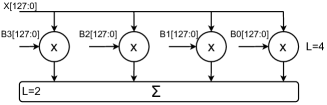
Another case when MCIM designs can be used is when there is a latency constraint. 6 represents a case where a latency constraint might be required. The example given requires 4 multiplications to be executed within 4 cycles since the summation block requires an additional 2 cycles. The only viable options for such a case are the Star multiplier with a latency of 4 (1C4L) and the feed-forward multiplier with a latency of 4 (2C4L). Using a single 1C4L multiplier violates the latency constraint by 3 cycles since it, additionally using 2 1C4L designs violates the latency constraint by 1 cycle, both these cases are more area-efficient than using 4 2C4L multipliers. However, they both violate the latency constraint. The only way to uphold the latency constraint is to use 4 individual multipliers in parallel. The 2C4L multiplier is the most area-efficient solution for this case, offering an area reduction of 47%, which can be very significant since 4 multipliers will be used in parallel (if ).
In Table VI, both the feed-forward design and Star achieve the same latency for a clock target of 0.8. If there is a latency constraint of 4 cycles, and the TP of these multipliers does not exceed 1/2, multiple instances of the feed-forward design can be used to calculate any number of multiplications, therefore providing great area savings. A similar case can be seen in Table VIII for 6464 multiplications. Such cases are only seen for large multiplications targeting a high frequency.
VI Conclusion
Various applications require a fractional number of multiplications per clock cycle, e.g., 3.5, where 7 multiplications are performed per 2 cycles. The conventional way of dealing with such cases is to utilize complete multipliers for these multiplications. This means that one of these multipliers will be underutilized. This approach is not optimal since it requires more area than necessary and does not take full advantage of the allocated resources. This work presents a range of multi-cycle unsigned integer multipliers, which offer an alternative to using single-cycle multipliers, which would be underutilized. The proposed designs provide significant area savings for various applications, as well as some energy savings.
Three main architectures are proposed in this work, each having different variations that can increase the area savings provided. The general approach of all our designs relies on the same concept: separating multiplication into three stages (PPM, compressor, and the final adder) and then applying resource sharing and pipelining to reduce the area complexity. Multiple architectures are used for each of these stages, which contribute to the area efficiency. MCIM designs are designed to maximize the area savings that can be provided for any application. Our architectures target specific types of applications with regard to the multiplication bit width, target frequency, and required TP.
The feedback architecture contains a feedback loop that increases the degree of resource sharing that is applied but limits the maximum frequency. It is often the optimal choice for applications running that do not require very high frequencies. This architecture can be used with any CT 2, making it suitable for a wide range of applications. The feed-forward architecture does not contain any feedback loops, allowing it to achieve very high frequencies while maintaining a lower area complexity than complete multipliers. This architecture is only area-efficient for a CT of 2, and it is the optimal architecture for applications requiring high frequencies. The Karatsuba architecture is optimized for large multiplications. They are often the optimal choice for multiplications with bit widths . The Karatsuba architecture contains a small feedback loop, thus, it is suitable for both low- and high-frequency applications. However, the feed-forward designs will always be faster since it can be continuously pipelined. The Karatsuba designs are optimal for a CT of 3.
MCIM designs with a CT of 2 can offer up to 48% area reductions and 33% energy savings with respect to a standard multiplication using the * operator. And can offer greater area savings for larger CTs. MCIM designs can be used for applications requiring a multiplier with a TP 5/6. Multiple instances of MCIM multipliers can also be used for applications with a latency constraint. Under strict timing conditions, MCIM designs can provide significant area savings while maintaining a latency equal to that of Star. In such cases, multiple MCIM designs can be used, providing great area savings. All MCIM designs use Verilog RTL generators that allow for various variations to be made regarding the latency, TP, and sub-modules. The generators allow MCIM designs to be easily modified according to the application requirements. The designs are thoroughly tested for various multiplication sizes and timing targets using automation scripts. The automation scripts handle design generation, synthesis, simulation, and report the results. Overall, these designs can offer significant area savings for unsigned integer multiplications for various applications. These designs can also be extended to handle unsigned integer multiplication. The designs are synthesized using the Synopsys Design Compiler and a TSMC 40 nm technology and simulated using Synopsys VCS.
References
- [1] C. Hoekstra, K. Shukla, and M. Harris, “Implementing high-precision decimal arithmetic with CUDA int128,” 2022, [Online]. Available: https://developer.nvidia.com/blog/implementing-high-precision-decimal-arithmetic-with-cuda-int128.
- [2] C. S. Wallace, “A suggestion for a fast multiplier,” IEEE Transactions on Electronic Computers, vol. EC-13, pp. 14–17, 1964.
- [3] L. Dadda, “Some schemes for parallel multipliers,” Alta Frequenza, vol. 34, pp. 349–356, 1965.
- [4] F. Ugurdag, O. Keskin, C. Tunc, F. Temizkan, G. Fici, and S. Dedeoglu, “RoCoCo: Row and column compression for high-performance multiplication on FPGAs,” in Proc. East-West Design & Test Symp. (EWDTS), 2011, pp. 98–101.
- [5] A. Kakacak, A. E. Guzel, O. Cihangir, S. Gören, and H. F. Ugurdag, “Fast multiplier generator for FPGAs with LUT based partial product generation and column/row compression,” Integration, vol. 57, pp. 147–157, 2017.
- [6] C. Rafferty, M. O’Neill, and N. Hanley, “Evaluation of large integer multiplication methods on hardware,” IEEE Transactions on Computers, vol. 66, pp. 1369–1382, 2017.
- [7] I. San and N. At, “On increasing the computational efficiency of long integer multiplication on FPGA,” in Proc. IEEE Int. Conf. on Trust, Security and Privacy in Computing and Communications (TrustCom), 2012, pp. 1149–1154.
- [8] J. Von Zur Gathen and J. Shokrollahi, “Efficient FPGA-based karatsuba multipliers for polynomials over F2,” in Proc. Selected Areas in Cryptography (SAC). Springer, 2005, pp. 359–369.
- [9] S. Gao, D. Al-Khalili, and N. Chabini, “Efficient scheme for implementing large size signed multipliers using multigranular embedded DSP blocks in FPGAs,” Int. Journal of Reconfigurable Computing, vol. 2009, 2009.
- [10] F. de Dinechin and B. Pasca, “Large multipliers with fewer DSP blocks,” in Proc. IEEE Int. Conf. on Field Programmable Logic and Applications (FPL), 2009, pp. 250–255.
- [11] M. Langhammer and B. Pasca, “Folded integer multiplication for FPGAs,” in Proc. ACM/SIGDA Int. Symp. on Field-Programmable Gate Arrays (FPGA), 2021, pp. 160–170.
- [12] M. Kumm, O. Gustafsson, F. de Dinechin, J. Kappauf, and P. Zipf, “Karatsuba with rectangular multipliers for FPGAs,” in Proc. IEEE Symp. on Computer Arithmetic (ARITH), 2018, pp. 13–20.
- [13] J. Li, Y. Du, and J. Wang, “Design a pocket multi-bit multiplier in FPGA,” in Proc. IEEE Int. Conf. on ASIC (ASICON), 1996, pp. 275–279.
- [14] M. R. Santoro and M. A. Horowitz, “SPIM: a pipelined 64*64-bit iterative multiplier,” IEEE Journal of Solid-state Circuits, vol. 24, pp. 487–493, 1989.
- [15] M.-C. Shin, S.-H. Kang, and I.-C. Park, “An area-efficient iterative modified-booth multiplier based on self-timed clocking,” in Proc. IEEE Int. Conf. on Computer Design: VLSI in Computers and Processors (ICCD), 2001, pp. 511–512.
- [16] M. C. Molina, R. Ruiz-Sautua, J. M. Mendias, and R. Hermida, “Area optimization of multi-cycle operators in high-level synthesis,” in Proc. IEEE Design, Automation & Test in Europe Conf. & Exhibition (DATE), 2007, pp. 1–6.
- [17] A. A. Karatsuba and Y. P. Ofman, “Multiplication of many-digital numbers by automatic computers,” in Proc. USSR Academy of Sciences (DAN SSSR). Russian Academy of Sciences, 1962, pp. 293–294.
- [18] Synopsys, “DesignWare Library,” available: https://www.synopsys.com/dw/buildingblock.php.
| Ahmad Houraniah received his BS in electrical and electronics engineering from Ozyegin University in 2020. He then completed his MS at Ozyegin University in 2022, majoring in computer science with a focus in computer arithmetic. He is currently working towards his PhD degree in CS. His research is focused on computer arithmetic and embedded systems. |
| H. Fatih Ugurdag is a full professor at Ozyegin University. He received his MS and PhD from Case Western Reserve University in EE in 1989 and 1995, respectively. He received his BS in EE with a double major in Physics from Bogazici University in 1986. He did an MS thesis on machine vision and a PhD dissertation on parallel hardware design automation. He worked in the industry in the USA between 1989-2004 at companies such as GE, GM, Lucent, Juniper, and Nvidia as a machine vision engineer, EDA software developer, and ASIC designer. In the late 2004, he joined academia. His research interests include real-time hardware/software design in the areas of video processing, communications, and automotive systems. |
| C. Emre Dedeagac received his BS in electrical and electronics engineering from Ozyegin University in 2020. He is currently working towards his PhD degree in computer science. His research is focused on neural network accelerators and computer arithmetic. Other topics he previously worked on include computer vision, machine learning, and high-frequency trading. |