Design of bistable soft deployable structures via a Kirigami-inspired planar fabrication approach
Abstract
Fully soft bistable mechanisms have shown extensive applications ranging from soft robotics, wearable devices, and medical tools, to energy harvesting. However, the lack of design and fabrication methods that are easy and potentially scalable limits their further adoption into mainstream applications. Here a top-down planar approach is presented by introducing Kirigami-inspired engineering combined with a pre-stretching process. Using this method, Kirigami-Pre-stretched Substrate-Kirigami trilayered precursors are created in a planar manner; upon release, the strain mismatch—due to the pre-stretching of substrate—between layers would induce an out-of-plane buckling to achieve targeted three dimensional (3D) bistable structures. By combining experimental characterization, analytical modeling, and finite element simulation, the effect of the pattern size of Kirigami layers and pre-stretching on the geometry and stability of resulting 3D composites is explored. In addition, methods to realize soft bistable structures with arbitrary shapes and soft composites with multistable configurations are investigated, which could encourage further applications. Our method is demonstrated by using bistable soft Kirigami composites to construct two soft machines: (i) a bistable soft gripper that can gently grasp delicate objects with different shapes and sizes and (ii) a flytrap-inspired robot that can autonomously detect and capture objects.
pacs:
Valid PACS appear hereI Introduction
The rapid development of soft robotics has recently attracted increasing attention from biology, chemistry, materials science, and engineering [1]. Fully soft machines and robots have shown the capability of outperforming conventional rigid counterparts in terms of adaptability, robustness, and safety [2]. Recently, bistable mechanisms—possess two stable equilibrium states—have been introduced into soft robotics for achieving high-performance and multi-functionalities [3]. They have demonstrated various innovative applications in fast grasping [4, 5, 6], shape reconfiguration [7, 8], information storage [9, 10], high-speed locomotion on ground [11, 12, 13] and water [14, 15], adaptive sensing [16], and mechanical oscillation [17, 18], computation [19, 20], and feedback controls [21] towards achieving autonomy for fully soft machines. Fabrication is non-trivial for fully soft bistable mechanisms, including both pre-shaped and pre-buckled ones [22]. Pre-shaped bistable mechanisms are either accomplished with vacuumed-involved casting procedures with customized molds [23, 24] or with free-form fabrication techniques (i.e., three dimensional printing) [25] with limited scalability and long fabrication times [26]. Likewise, pre-buckled ones often require constrained boundary to precisely impose buckling load [27, 28], which could increase the fabrication difficulty and restrain their applications. Therefore, it is desired to introduce a method for fabrication and programming of fully soft bistable mechanisms that are easy to generate and potentially scalable, which could encourage their further adoption into mainstream applications.
Recently, pre-stretching method on generating three dimensional (3D) structures and mechanisms from planer bilayered precursors (structures before 3D deployment) has drawn increasing attentions thanks to their scalability and ease for fabrication [29, 30, 31]. The planer precursors often consist of a pre-stretched substrate with a bonded top layer; upon released, the substrate imposes compressive load on the top layer to force the bilayered precursor into 3D morphology [32]. However, to introduce bistability or even multistability, a spatial variation of thickness and selected bonding pattern for the top layer are necessary [33]. These two technologies could enable the creation of more delicate 3D configurations while sacrificing the ease of fabrication.
A promising alternative method is to bring in Kirigami-inspired engineering onto the top layer (with uniform thickness); the designated pattern on the top layer could potentially guide the resulting composite to deform into a pre-programmed geometry without requiring neither a spatial variation of thickness of the top layer nor specified bonding pattern [34, 35, 36, 37]. This Kirigami-inspired pre-stretching method has enabled various applications, including deployable 3D shapes [34], self-assembly structures [38], etc. [39]. Yet, the capability of introducing bistability within this design paradigm has not been demonstrated. Specifically, a scalable and simple manufacturing method that enables the usage of the uniform material and bonding could create a pathway for broad adoption of fully soft bistable mechanisms into intelligent soft machines and robots.
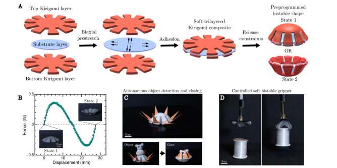
Here we propose an easy and scalable process to create fully soft bistable mechanisms from 2D preprogrammed precursors. This approach introduces the bistability through bonding one central pre-stretched substrate with two identical Kirigami top and bottom layers. Once released, the trilayered composite deforms into a 3D free-buckling configuration with two stable equilibrium, as schematically shown in Figure 1A and B. Our method allows us to only use commercially available soft elastomer sheet materials, which could vastly simplify the fabrication processes. We combine physical experiment, finite element simulation, and composite shell theory to explore and predict the transition from 2D to 3D shapes and the properties of the resulting bistable mechanisms. We show methods to create soft bistable structures with arbitrary shapes and sizes by combining optimal design results from machine learning algorithm with scaling analysis. In addition, we explore the multistability of proposed trilayered composites through experiment and simulation. We demonstrate this generic design and fabrication method by creating (i) an universal, nondestructive soft gripper that allows stable grasping of delicate objects such as a strawberry or a butter packet; and (ii) a flytrap-inspired robot that can autonomously sense and swiftly capture objects (see Figure 1C and D, and Movie S1). This work opens a new avenue to generate fully soft bistable mechanism with potential applications in wearable devices, soft robotics, and multifunctional medical devices.
II Results and Discussion
II.1 Design concept
Figure 1 presents our concept of designing bistable soft composites. We start with a substrate layer and two identical outer layers with the same Kirigami design cutouts (Figure 1A). The Kirigami layers in this example resemble a lotus shape. First, a biaxial stretch is induced on the substrate layer. Then, the two unstretched Kirigami layers are aligned and bonded at the top and the bottom of the pre-stretched substrate layer, generating symmetry to the composite about the substrate (Figure 1). The material removal in the Kirigami layers can help the laminated trilayered structure to achieve targeted global shapes with smooth transition instead of wrinkling in the local regions [40]. Once released, the strain mismatch between the three layers induces out-of-plane buckling since bending is less energetically expensive than compression for thin shells [41].
II.2 Desktop-Scale Physical Experiments
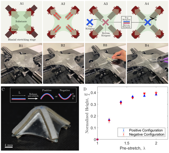
Figure 2 presents the experimental setup for fabricating trilayered bistable structures. The experimental setup consists of four linear translation stages (250 mm travel, Thorlabs, Inc.). The substrate and the Kirigami layers are made of hyper-elastic materials. The material properties are listed in Table LABEL:table:matparam. We fit the experimentally measured stress-strain curve using the Mooney Rivlin material model. The material constants for the Kirigami layer are and , while the constants for the substrate layer are denoted as and . An arbitrarily large substrate layer is fixed with its four corners attached onto the four stages, respectively (Figure 2A1 and B1). Then, to impose the biaxial stretch upon the substrate, we induce the substrate layer with the same amount of stretch in both directions (Figure 2A2 and B2). Once stretching is complete, two Kirigami layers are attached on the top and bottom of the substrate layer directly since both sides of layers already have strong adhesive agent (Figure 2A3 and B3). The excess substrate is cut away along a defined bonding box, which is designed according to the desired resulting shape (Figure 2A4 and B4). Once released, this planar composite structure then morphs to either one of the two possible stable configurations arising due to the strain mismatch within layers.
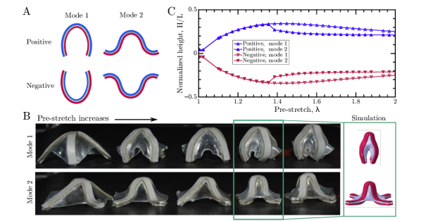
For our experimental study, we chose cross-shaped Kirigami layers and square-shaped substrate layers. With the appropriate value of pre-stretch , these geometric designs of the layers provide a deformed shape that looks like a pyramid. Figure 2C displays one such soft pyramid bistable structure. The length of the 2D precursor is denoted as while the height of the buckled 3D pyramid is as shown in the insert of Figure 2C. We define the configuration it immediately converged to after removing the boundary condition as the “positive” configuration, while the inverted one as the “negative” configuration. Before the measurements were performed, both “positive” and “negative” configurations were given a sufficient period of time to settle down. As the pre-stretch increases, the normalized height (= ) of the pyramid increases in a nonlinear manner, as shown in Figure 2D. The normalized height for the “positive” and “negative” configurations were close to each other for this size of composite structure with mm.
II.3 Finite element-based numerical simulations
The finite element software, Abaqus [42], was used to model the nonlinear large deformation of the hyper-elastic composite structures. In the simulations, we used the same pyramid shape and simulated the hyper-elastic materials of the substrate and the two Kirigami layers using Mooney Rivlin material models. Solid elements (C3D6) were used to model the layers of the composite structure. Each layer of the composite was modelled with multiple sub-layers of elements to accurately predict the deformation of the structure along its thickness. Each sub-layer was meshed with two sets of 4521 nodes, with the substrate and the kirigami having 2198 and 6046-node prismatic elements per sub-layer, respectively. The symmetry of the Kirigami was taken into account for the mesh. Furthermore, the elements at the interface of the material layers shared nodes constraining their deformation in a way similar to the layers being bonded together. The center of the composite structure was set fixed. The pre-stretch was induced by describing an initial stress condition on the substrate layer. This initial stress was calculated as the Cauchy stress () arising in a Mooney-Rivlin hyperelastic material (Parameters: , due to a given equibiaxial stretch ().
| (1) |
A nonlinear quasi-static deformation process was simulated with a very small but non-zero distributed force on the structure to force it into one of the two possible stable configurations, which we termed as the “positive” configuration.
One numerical simulation took about 1-3 minutes wall clock time on a desktop computer (Ryzen 2950wx CPU @ 2.4 GHz). To understand the variation of the final shape with pre-stretch, the simulation was run for multiple values of pre-stretches. The height of the structure was studied by procuring the maximum and minimum values of the out-of-plane nodal coordinates. Further details on this study have been described in Section II.5.
We also study the other stable configuration than the one the simulation initially provides. This is simulated by modelling a force-based actuation on the obtained configuration. Force is applied on four symmetrically placed nodes on the arms of the cross-shaped Kirigami layer, pushing the structure into the other stable configuration. This actuation provides us with details about the “negative” configuration of the structure as well as brings to light the multiple stable modes that a structure could have as further described in Section II.6.
II.4 Analytical derivation
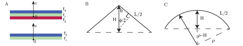
Figure 3A shows the cross-sectional views of the soft Kirigami composite structure before bulking. The thickness of the substrate and Kirigami layers are denoted as and , respectively. We assume that after the free buckling, the initial stretching energy of the substrate layer is transformed into the bending energy of the whole composite structure. This is because that bending energy is less energetically expensive than compression for thin shells [41]. Considering the hyperelastic property of the system, the stretching-induced energy is,
| (2) |
where is the pre-stretch, which is the ratio of the stretched substrate size over the unstretched size . is the area of the unstretched substrate. For the square-like substrate, .
For small strain, we can approximate the stretching-induced energy for the substrate layer as,
| (3) |
where . and are the Young’s modulus and Poisson’s ratio of the substrate layer, respectively.
Meanwhile, the bending energy can be calculated as,
| (4) |
where is the equivalent bending stiffness of the trilayer, which is derived in the supplementary material. From the observation of the deformed 3D shapes, we further assume that the deformed shape is close to a pyramid shape, with the side view sketched in Figure 3B. For the pyramid like shape, the curvature is related by the angle , the half-length of the cross shape , and the height of the pyramid via the equations as follows,
| (5) |
| (6) |
Hence, equalizing the bending energy and stretching energy, and combining equation 5 and 6 gives,
| (7) |
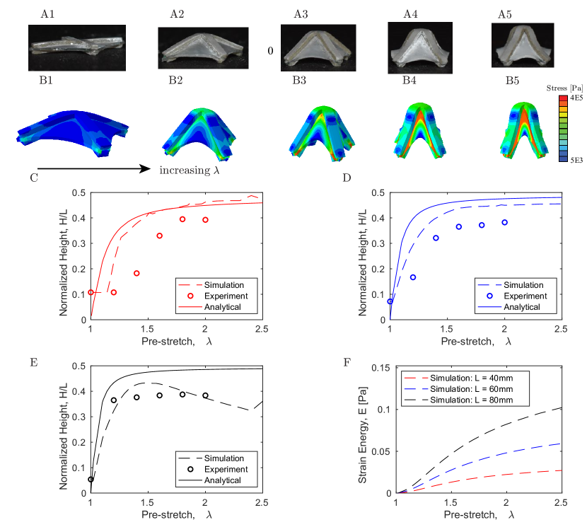
Since function is bounded between 0 and , the normalized height, , is bounded between 0 and 0.5. This helps explain why in both simulations and experiments, the normalized heights plateau at very large amount of pre-stretches in in Figure 4. It can be found that the simplified analytical model agrees well with the experiments and simulations, which further verifies the concept of shape-forming trilayer structures.
II.5 Effect of size and pre-stretch on free buckling shapes
In this section, we focus on the cross-shaped Kirigami layers with square-shaped substrate as shown in Figure 2. The thickness of the material is denoted as (including and for the substrate and Kirigami layer, respectively), the length and width of the kirigami are denoted as and , respectively.
For a fixed size of kirigami composite structure, we first investigate the effect of prestretch on the buckling shapes. A few examples of Kirigami composites with different amount of pre-stretches are presented in Figure 4 A and B. The geometry in simulations agrees well with the results of experiments. The height of the composite structure increases with the amount of pre-stretch, as shown in Figure 4C to E. This is because with the increase in strain energy in Figure 4F, the converted shell bending energy becomes larger. There exists a certain threshold, below which the composite structure hardly buckles. Despite the assumptions introduced in the analytical model, the experiment, simulation and analytical model exhibit similar trend. As pre-stretch increases, the maximum heights of these pyramid-like 3D shapes are bounded by a certain maximum.
We further increase the length , but fix the length/width ratio, , and the thickness of the composite structure . This means that the ratio of length/thickness, , is increased. Figure 4C, D and E present the variation of normalized height at different . At the same level of pre-stretch, the maximum normalized height for the pyramid tends to be larger for thinner composite structures (with larger ). Such a behavior can be understood from the scaling relationship in Equation 7.
II.6 Multistability
As increases to mm, we find there could be multiple free-buckling mode shapes in the positive and negative configurations, as shown in Figure 5 A and B. This behavior is not observed for thicker composite structures with larger in Figure 4. For the kirigami composite of mm, a systematic variation finds that, at a small pre-stretch, the free buckling shape is dominated by the mode 1 defined in Figure 5A. As the amount of pre-stretch increases, the mode 2 type emerges. The four edges of the cross-sections start to buckle locally. In the two modes, the cross shapes buckle in different directions. This leads to the difference in the height of the two modes presented in Figure 5C. Considering the symmetry of the trilayered structure, the soft structures in this case have four stable configurations. Such a multistable behavior further functionalizes the structure to possess more mechanical properties. This also opens the door of conducting systematic analytical research to understand the mechanism behind the multi-stability phenomena in the future.
II.7 Creating the trilayer bistable structures that achieve target 3D shape
Based on the same design concept of combining Kirigami structures and strain mismatch, Miha et al. and Ma et al. [36] for the first time demonstrated that the planar bilayered composite can be deformed to 3D soft structures. Ma et al. [37] further developed a machine learning-aided approach to explore the optimal Kirigami cuts, pre-stretch and Kirigami size that achieves targeted 3D shapes, such as peanuts and flowers. The previous research enables rapid prototyping of soft Kirigami structures through a Kirigami bilayered composite structure. If we continue to add more Kirigami layers in the system, we can introduce bistability for these soft kirigami structures, which can be used for wider applications, such as biomimetics [34] and soft actuators [23].
Even though the proposed machine learning approach by Ma et al. [37] reduces the number of searches from millions of designs to order of hundreds, it still takes about 6 hours of computational time on a desktop computer (Ryzen 2950wx CPU @ 2.4 GHz). In this section, we want to test whether we can achieve similar targeted 3D bistable structures just by modifiying the size and the amount of pre-stretch while keeping the optimized Kirigami patterns the same as the bilayered counterparts. To achieve this goal, we make use of the scaling analysis derived from the energy conservation.
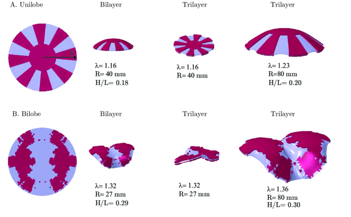
The 3D shapes we focus on in this section are the unilobe shape and the bilobe shape (Figure 6). For these 3D shapes, we can assume the curvature is approximately the same everywhere. In this case, the relationship between the curvature and height is derived in the supplementary information. Then, equalizing the bending energy and stretching energy, the normalized height can be approximated by
| (9) |
For the structure of a certain radius , the bending stiffness for the trilayer is about 3 times of the bilayer counterpart. Figure 6 shows two examples where the Kirigami patterns in the first column can be used to create a target unilobe and a bilobe bilayer structures in the second column [36, 37]. The material properties for the substrate and Kirigami layers are shown in Table LABEL:table:matparam. The material constants for the Kirigami layer leading to unilobe structures are and . While the constants for kirigami that creates the bilobe shape are and . If we apply the same amount of pre-stretch to the trilayer structure of the same size as the bilayer counterpart, then the free-buckling shape is still flat in the plane. This is due to the increased stiffness in the system. To create the targeted 3D shapes of similar height ratio , the pre-stretch and size need to be adjusted according to Equation 9. The last column in Figure 6 shows some examples when the pre-stretch varies near the value for the bilayer counterpart but the radius of the structure is increased, we can still fabricate unilobe and bilobe shapes of similar using these trilayer composite structures.
There also exists a limiting condition when the scaling relationship can be further simplified. When the thickness of the substrate is very thin, and the bending stiffness of the substrate is negligible, the equivalent bending stiffness of the trilayer is about 8 times of the bilayer counterpart with the same size. Hence the or size needs to be increased to approximately of the bilayer structure.
II.8 Applications of bistable, soft Kirigami composites
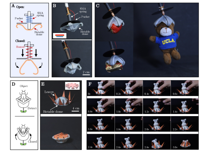
To show the potential applications, we used bistable soft Kirigami composites to realize two soft machines: (i) A bistable soft gripper that can grasp delicate objects with different shape and size (see Figure 7A-C); (ii) A flytrap-inspired robot that can autonomously and passively sense and capture objects (see Figure 7D-F).
The soft gripper is mainly composed of a bistable dome ( gram, with cross-shaped Kirigami layers), an extending shape memory alloy (SMA) spring, and a mechanical pusher (see Figure 7A). The center of the bistable dome is attached on the end of a rail. One end of the SMA spring is fixed on the rail while the other is joined with the pusher. The spring can be activated by Joule heating through electrical power. Thus, the bistable dome stays at the upward stable equilibrium when unactuated; the pusher can glide along the rail when the SMA spring is powered and eventually causes the dome to snap-through to the other stable state. To facilitate the grasping, we modified the original Kirigami pattern by extending the top Kirigami and substrate layers on the edges so that the added parts of the dome can form hook-shaped structures locally as shown in Figure 7(B). This shows the potential of our method to generate more sophisticated 3D structures to enable more functionalities through a monolithic planar process. We show the ability of our gripper by grasping various fragile objects, including a strawberry (15 gram), a butter packet (9.7 gram), and an UCLA plush bear (12.6 gram) as shown in Figure 7C. We also demonstrate sturdy grasping of a cable spool (25.3 gram, Figure 1D, see supplementary video for details) under moderate disturbance. It is worth noting that we only need energy during the transition phase while no energy is required to keep the gripper closed, which could save considerable amount of energy for applications where long grasping time is necessary.
The flytrap-inspired robot consists of a bistable trilayered dome (with lobe-shaped Kirigami layers) with triangular leaves (see Figure 7E). The transition of the robot from the open state to the closed one happens by applying a minimum loading force. This snap-through transition with the intrinsic energy barrier can function as embedded sensing and fast actuation to autonomously capture object. We demonstrate this by placing a self-made toy (made from Plasticine) on the center of the robot; the loading causes the bistable dome to snap through and thus quickly close leaves to trap the object. The closing happened within 0.4 s (see Figure 7 F, see supplementary video for details) while the toy maintains intact thanks to the softness of the trap. To facilitate the transition, we harnessed magnetic force by attaching a magnetic bead on the bottom of the toy with another magnetic bead underneath the robot. Although this is out of scope of this paper, we could lower the energy barrier by using thinner sheet materials or reduce pre-stretch to further release the requirement for magnetic beads. This embedded sensing and actuation into soft material could reduce the complexity and weight, and increase the adaptability of resulting devices; without requiring external electronic control and actuation could also make our robots applicable for cases where conventional electronics can not survive.
III Concluding Remarks
In this paper, we numerically and experimentally studied the influential parameters on how an initially planar substrate layer and two Kirigami layers can be used to fabricate bistable soft 3D structures. The structure size and applied pre-stretch are found to be very critical in affecting the geometry and the stablility of the free-buckling shapes. By introducing analytical analysis to the optimized kirigami patterns for bilayer counterparts, we found that by carefully adjusting the pre-stretch and structural size, we are able to directly extending the 3D shapes designed for bilayers to trilayer structures. This combined approach provides a rapid way of designing and fabricating soft, bistable composite structures of different targeted 3D shapes. The proposed fabrication techniques, systematic parametric analysis, and mathematical modelings can lay a foundation in applications in soft robotics, and wearable devices etc. We demonstrate the advantage of using these soft bistable structures in engineering tasks that requires fast grasping and stable manipulation for delicate objects, and autonomous object detection and fast object capturing.
IV Source code
The source code for Finite Element Simulation for all conducted simulation tests can be found at https://github.com/StructuresComp/bistable-kirigami.
V Supplementary
V.1 Relationship between the curvature and the maximum height for spherical cap shapes
We further assume that the deformed shape is close to a spherical cap shape with maximum height , and has approximately constant curvature everywhere, as shown in Figure 3C. The length of the curve can be approximated as,
| (10) |
where is the radius of the hemisphere, which is related to the curvature via . Hence,
| (11) |
V.2 Equivalent bending stiffness for composite shells
Figure 3A shows the cross-sectional view of the bilayer and trilayer composite structures. The neutral axis of the trilayer is in the center of the substrate. Hence, the equivalent bending stiffness is,
| (12) |
where is the fraction of the area covered by the kirigami layer. and is the thickness of the substrate and kirigami layer, respectively. and is the approximated Young’s modulus of the substrate and kirigami layer, respectively.
While the z position of the neutral axis for the bilayer is calculated as,
| (13) |
For the bilayer structures, the equivalent bending stiffness is,
| (14) |
| Parameter | Value | Unit |
|---|---|---|
| Material constant | 22.1 | KPa |
| Material constant | 1.7 | KPa |
| Thickness | 1.1 | mm |
| Material constant | 17.9 | KPa |
| Material constant | 84.5 | KPa |
| Thickness | 1.6 | mm |
| Material constant | -2.6 | KPa |
| Material constant | 185.8 | KPa |
| Thickness | 1.4 | mm |
Supporting Information
Supporting Information is available from the Wiley Online Library or from the author.
Acknowledgements
We thank Shyan Shokrzadeh and Vishal Kackar for their assistance on experiments. Following research grants are gratefully acknowledged: NSF (CMMI-2053971) for L.M., M.M., and M.K.J.; and NSF (CAREER-2047663, CMMI-2101751, OAC-2209782) for M.K.J.
References
- [1] Daniela Rus and Michael T Tolley. Design, fabrication and control of soft robots. Nature, 521(7553):467–475, 2015.
- [2] George M Whitesides. Soft robotics. Angewandte Chemie International Edition, 57(16):4258–4273, 2018.
- [3] Yinding Chi, Yanbin Li, Yao Zhao, Yaoye Hong, Yichao Tang, and Jie Yin. Bistable and multistable actuators for soft robots: Structures, materials, and functionalities. Advanced Materials, 34(19):2110384, 2022.
- [4] Richard Baumgartner, Alexander Kogler, Josef M Stadlbauer, Choon Chiang Foo, Rainer Kaltseis, Melanie Baumgartner, Guoyong Mao, Christoph Keplinger, Soo Jin Adrian Koh, Nikita Arnold, et al. A lesson from plants: high-speed soft robotic actuators. Advanced Science, 7(5):1903391, 2020.
- [5] Elisha Lerner, Haijie Zhang, and Jianguo Zhao. Design and experimentation of a variable stiffness bistable gripper. In 2020 IEEE/RSJ International Conference on Intelligent Robots and Systems (IROS), pages 9925–9931. IEEE, 2020.
- [6] Jiefeng Sun, Brandon Tighe, and Jianguo Zhao. Tuning the energy landscape of soft robots for fast and strong motion. In 2020 IEEE International Conference on Robotics and Automation (ICRA), pages 10082–10088. IEEE, 2020.
- [7] Yuzhen Chen, Tianzhen Liu, and Lihua Jin. Spatiotemporally programmable surfaces via viscoelastic shell snapping. Advanced Intelligent Systems, page 2100270, 2022.
- [8] Jakob A Faber, Janav P Udani, Katherine S Riley, André R Studart, and Andres F Arrieta. Dome-patterned metamaterial sheets. Advanced Science, 7(22):2001955, 2020.
- [9] Tian Chen, Mark Pauly, and Pedro M Reis. A reprogrammable mechanical metamaterial with stable memory. Nature, 589(7842):386–390, 2021.
- [10] Hiromi Yasuda, Tomohiro Tachi, Mia Lee, and Jinkyu Yang. Origami-based tunable truss structures for non-volatile mechanical memory operation. Nature communications, 8(1):1–7, 2017.
- [11] Benjamin Gorissen, David Melancon, Nikolaos Vasios, Mehdi Torbati, and Katia Bertoldi. Inflatable soft jumper inspired by shell snapping. Science Robotics, 5(42):eabb1967, 2020.
- [12] Yongjin Kim, Jay van den Berg, and Alfred J Crosby. Autonomous snapping and jumping polymer gels. Nature Materials, 20(12):1695–1701, 2021.
- [13] Zechen Xiong, Yufeng Su, and Hod Lipson. Fast untethered soft robotic crawler with elastic instability. arXiv preprint arXiv:2210.02352, 2022.
- [14] Yinding Chi, Yaoye Hong, Yao Zhao, Yanbin Li, and Jie Yin. Snapping for high-speed and high-efficient, butterfly swimming-like soft flapping-wing robot. arXiv preprint arXiv:2204.05987, 2022.
- [15] Tian Chen, Osama R Bilal, Kristina Shea, and Chiara Daraio. Harnessing bistability for directional propulsion of soft, untethered robots. Proceedings of the National Academy of Sciences, 115(22):5698–5702, 2018.
- [16] Katherine S Riley, Subhadeep Koner, Juan C Osorio, Yongchao Yu, Harith Morgan, Janav P Udani, Stephen A Sarles, and Andres F Arrieta. Neuromorphic metamaterials for mechanosensing and perceptual associative learning. arXiv preprint arXiv:2203.10171, 2022.
- [17] Philipp Rothemund, Alar Ainla, Lee Belding, Daniel J Preston, Sarah Kurihara, Zhigang Suo, and George M Whitesides. A soft, bistable valve for autonomous control of soft actuators. Science Robotics, 3(16):eaar7986, 2018.
- [18] Wenzhong Yan and Ankur Mehta. A cut-and-fold self-sustained compliant oscillator for autonomous actuation of origami-inspired robots. Soft Robotics, 2021.
- [19] Daniel J Preston, Philipp Rothemund, Haihui Joy Jiang, Markus P Nemitz, Jeff Rawson, Zhigang Suo, and George M Whitesides. Digital logic for soft devices. Proceedings of the National Academy of Sciences, 116(16):7750–7759, 2019.
- [20] Wenzhong Yan, Chang Liu, and Ankur Mehta. Origami logic gates for printable robots. In 2021 IEEE/RSJ International Conference on Intelligent Robots and Systems (IROS), pages 6084–6089. IEEE, 2021.
- [21] Dylan Drotman, Saurabh Jadhav, David Sharp, Christian Chan, and Michael T Tolley. Electronics-free pneumatic circuits for controlling soft-legged robots. Science Robotics, 6(51):eaay2627, 2021.
- [22] Aniket Pal, Vanessa Restrepo, Debkalpa Goswami, and Ramses V Martinez. Exploiting mechanical instabilities in soft robotics: control, sensing, and actuation. Advanced Materials, 33(19):2006939, 2021.
- [23] Yuhang Liu, Kai Luo, Shuai Wang, Xiaodong Song, Zhijuan Zhang, Qiang Tian, and Haiyan Hu. A soft and bistable gripper with adjustable energy barrier for fast capture in space. Soft Robotics, 2022.
- [24] Xing Wang, Aarjav Khara, and Chao Chen. A soft pneumatic bistable reinforced actuator bioinspired by venus flytrap with enhanced grasping capability. Bioinspiration & Biomimetics, 15(5):056017, 2020.
- [25] Hong Kai Yap, Hui Yong Ng, and Chen-Hua Yeow. High-force soft printable pneumatics for soft robotic applications. Soft Robotics, 3(3):144–158, 2016.
- [26] Trevor J Jones, Etienne Jambon-Puillet, Joel Marthelot, and P-T Brun. Bubble casting soft robotics. Nature, 599(7884):229–233, 2021.
- [27] Thomas George Thuruthel, Syed Haider Abidi, Matteo Cianchetti, Cecilia Laschi, and Egidio Falotico. A bistable soft gripper with mechanically embedded sensing and actuation for fast grasping. In 2020 29th IEEE International Conference on Robot and Human Interactive Communication (RO-MAN), pages 1049–1054. IEEE, 2020.
- [28] Shuang Wu, Gregory Langston Baker, Jie Yin, and Yong Zhu. Fast thermal actuators for soft robotics. Soft Robotics, 2021.
- [29] Sheng Xu, Zheng Yan, Kyung-In Jang, Wen Huang, Haoran Fu, Jeonghyun Kim, Zijun Wei, Matthew Flavin, Joselle McCracken, Renhan Wang, et al. Assembly of micro/nanomaterials into complex, three-dimensional architectures by compressive buckling. Science, 347(6218):154–159, 2015.
- [30] Zhichao Fan, Yiyuan Yang, Fan Zhang, Zheng Xu, Hangbo Zhao, Taoyi Wang, Honglie Song, Yonggang Huang, John A Rogers, and Yihui Zhang. Inverse design strategies for 3d surfaces formed by mechanically guided assembly. Advanced Materials, 32(14):1908424, 2020.
- [31] Mingchao Liu, Lucie Domino, and Dominic Vella. Tapered elasticæ as a route for axisymmetric morphing structures. Soft Matter, 16(33):7739–7750, 2020.
- [32] Zheng Yan, Fan Zhang, Jiechen Wang, Fei Liu, Xuelin Guo, Kewang Nan, Qing Lin, Mingye Gao, Dongqing Xiao, Yan Shi, et al. Controlled mechanical buckling for origami-inspired construction of 3d microstructures in advanced materials. Advanced functional materials, 26(16):2629–2639, 2016.
- [33] Guoquan Luo, Haoran Fu, Xu Cheng, Ke Bai, Liping Shi, Xiaodong He, John A Rogers, Yonggang Huang, and Yihui Zhang. Mechanics of bistable cross-shaped structures through loading-path controlled 3d assembly. Journal of the Mechanics and Physics of Solids, 129:261–277, 2019.
- [34] Jianxun Cui, Felipe R Poblete, and Yong Zhu. Origami/kirigami-guided morphing of composite sheets. Advanced Functional Materials, 28(44):1802768, 2018.
- [35] Yunlan Zhang, Jingyi Yang, Mingchao Liu, and Dominic Vella. Shape-morphing structures based on perforated kirigami. Extreme Mechanics Letters, 56:101857, 2022.
- [36] Jan Zavodnik, Yunbo Wang, Wenzhong Yan, Miha Brojan, and M. Khalid Jawed. Soft kirigami composites for form-finding of fully flexible deployables. arXiv preprint, 2023.
- [37] Leixin Ma, Mrunmayi Mungekar, Vwani Roychowdhury, and Mohammad Khalid Jawed. Rapid design of fully soft deployable structures via kirigami cuts and active learning. arXiv preprint, 2023.
- [38] Teunis van Manen, Shahram Janbaz, Mahya Ganjian, and Amir A Zadpoor. Kirigami-enabled self-folding origami. Materials Today, 32:59–67, 2020.
- [39] Yihui Zhang, Fan Zhang, Zheng Yan, Qiang Ma, Xiuling Li, Yonggang Huang, and John A Rogers. Printing, folding and assembly methods for forming 3d mesostructures in advanced materials. Nature Reviews Materials, 2(4):1–17, 2017.
- [40] Joseph D Paulsen, Evan Hohlfeld, Hunter King, Jiangshui Huang, Zhanlong Qiu, Thomas P Russell, Narayanan Menon, Dominic Vella, and Benny Davidovitch. Curvature-induced stiffness and the spatial variation of wavelength in wrinkled sheets. Proceedings of the National Academy of Sciences, 113(5):1144–1149, 2016.
- [41] Matteo Pezzulla, Gabriel P Smith, Paola Nardinocchi, and Douglas P Holmes. Geometry and mechanics of thin growing bilayers. Soft matter, 12(19):4435–4442, 2016.
- [42] Michael Smith. ABAQUS/Standard User’s Manual, Version 6.9. Dassault Systèmes Simulia Corp, United States, 2009.