Is Boeing 737-MAX Still Safe?
Analysis and Prevention of MCAS-Induced Crashes
Abstract
Semi-autonomous (SA) systems face the problem of deciding whether to select control input from the human operator or autonomous controller when they conflict with each other. While one may design an SA system to default to accepting control from one or the other, such design choices can have catastrophic consequences in safety-critical settings. For instance, the sensors an autonomous controller relies upon may provide incorrect information about the environment due to tampering or natural wear. On the other hand, the human operator may also provide dangerous input. This begs an important question: Can we convert an existing SA system to make dynamic real-time control decisions that are tolerant of erroneous/malicious input?
To explore this question in this paper, we investigate a specific application of an SA system that failed due to a static assignment of control authority. Namely, the well-publicized failure of the Boeing 737-MAX Maneuvering Characteristics Augmentation System (MCAS) that caused the crashes of Lion Air Flight 610 and Ethiopian Airlines Flight 302. First, through in-depth real-time simulation, we analyze and demonstrate the ease by which the original MCAS design could fail. Our analysis reveals several novel vectors of failure that were not present in the original crashes. We also analyze Boeing’s revised MCAS and show how it falls short of its intended goals. Using these insights, we present Semi-Autonomous MCAS (SA-MCAS), a new MCAS that both meets the intended goals of MCAS and avoids the failure cases that plagued the original MCAS design. We demonstrate SA-MCAS’s ability to make correct control decisions of the aircraft, even when the human and autonomous operators provide conflicting control inputs.
1 Introduction
Semi-autonomous (SA) systems—those that take both autonomous and manual inputs to control their actions—are ubiquitous in the modern world, presenting applications in factories, hospitals, transportation, and more. Often, the purpose of these systems is to improve the safety and efficiency of tasks that take substantial manual effort. Airplanes, for example, use SA control to maintain safe flight while pilots perform other tasks. As a consequence of SA systems’ close coupling with safety-critical applications, there is a complicated trade-off between trusting human and autonomous inputs. SA functionality is often included in a system because humans are prone to making mistakes, but autonomous systems are also imperfect, leading to distrust from human operators.
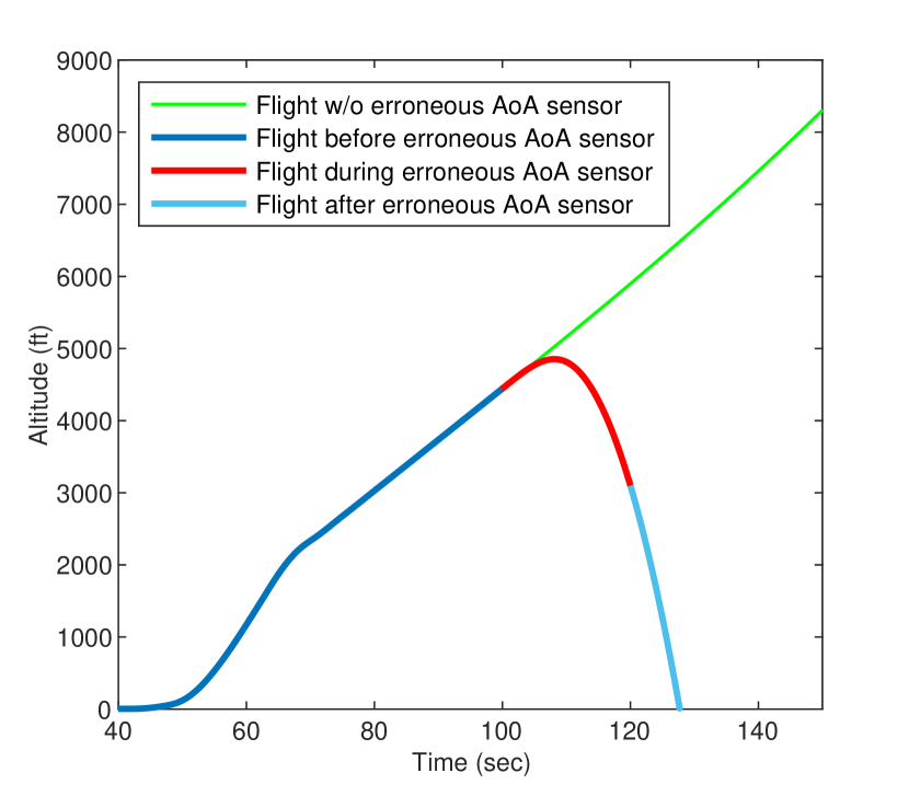
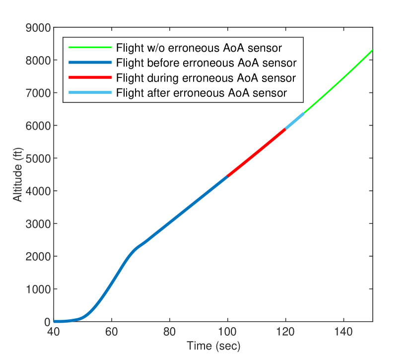
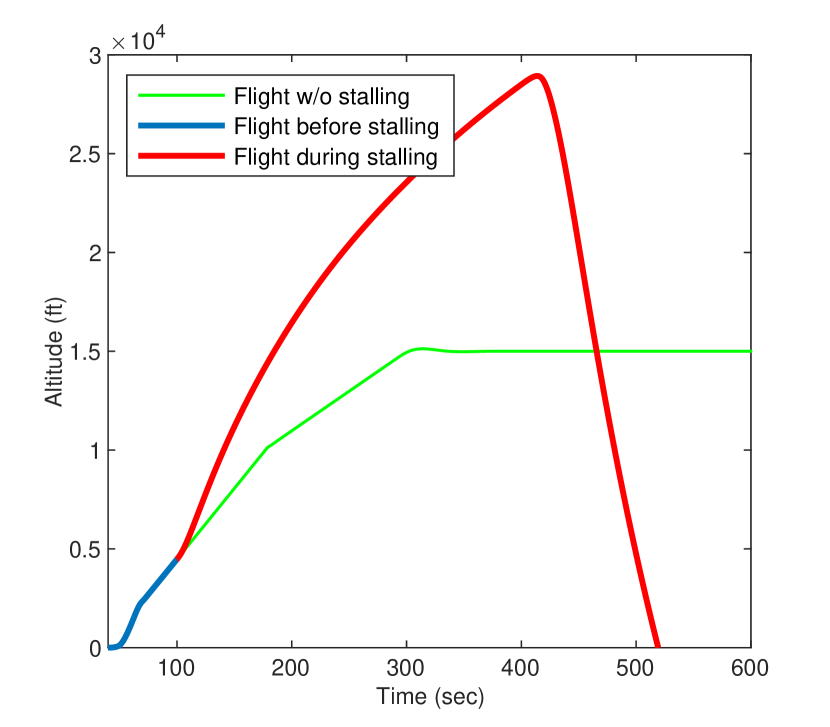
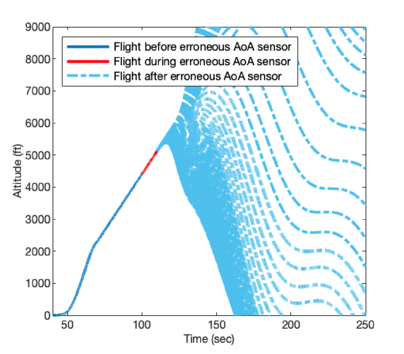
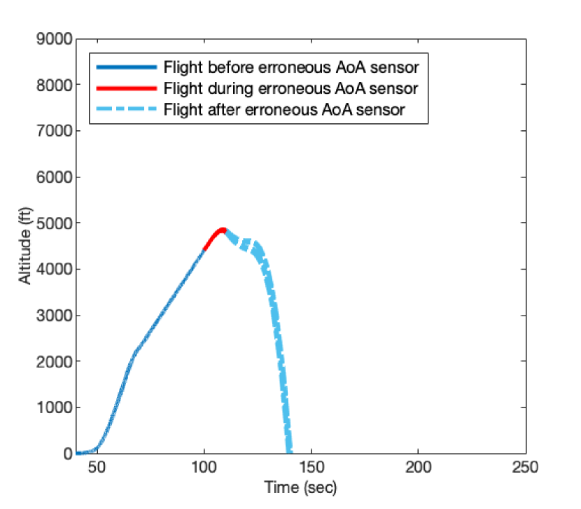
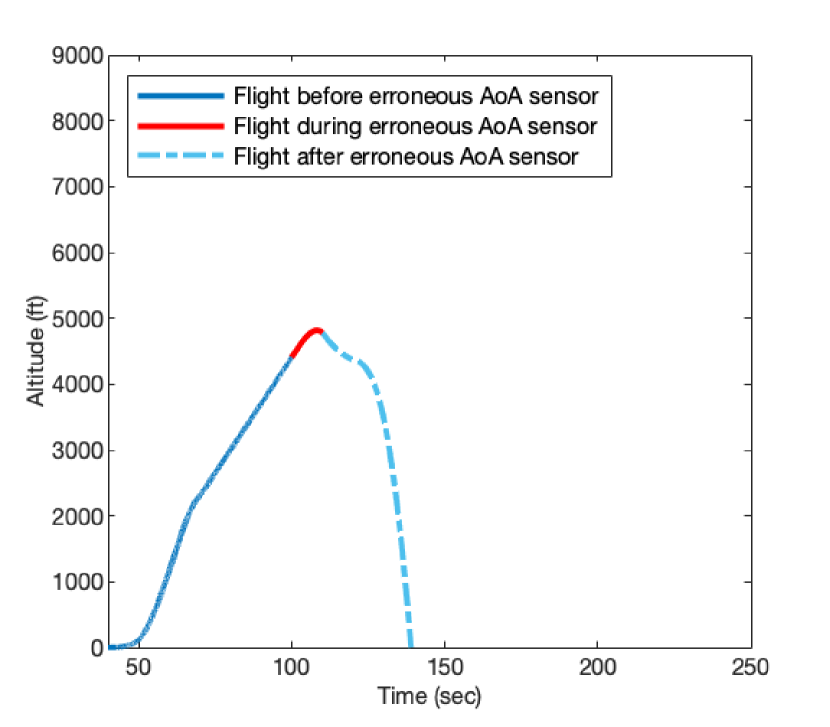
SA systems have a tendency to be hard-coded to “trust” the input from one entity over the other. For instance, an autonomous system in the Boeing 737-MAX, the Maneuvering Characteristics Augmentation System (MCAS), was originally given immense authority over the control of the pitch of the aircraft during aircraft stall events. This decision was motivated by a lack of trust in pilot control during these safety-critical stall events, and it had dire consequences: In 2019, the MCAS played a devil’s role in the crash of two Boeing 737-MAX aircraft—Lion Air Flight 610 (JT610) and Ethiopian Arlines Flight 302 (ET302). These crashes led to a redesign of the MCAS that greatly shifted the balance of control away from the MCAS, and towards the pilots. To motivate this work, we hypothesize that the MCAS redesign abandons its original responsibility of avoiding stalls due to dangerous pilot pitch control. To test this simple hypothesis, we conduct a preliminary analysis and demonstrate that Boeing’s revised MCAS fixes the problems of the original MCAS in exchange for our hypothesized new issues related to pitch control (see Fig. 2).
From a security and reliability perspective, we argue that this is the wrong solution to the MCAS problem. Giving one entity full authority to control a safety-critical application without considering other conflicting control inputs creates the possibility of a single point-of-failure. We assert that rather than defaulting the control to one entity, the control should be dynamically chosen based on the vehicle’s situation. By moving the target, MCAS is more tolerant of erroneous/malicious input from either autonomous or manual control.
Following this design philosophy and using the Boeing 737-MAX case study, we propose Semi-Autonomous MCAS (SA-MCAS). Unlike the existing implementations of MCAS, SA-MCAS is capable of providing safer control of the aircraft’s pitch in the presence of erroneous input from either autonomous or manual control.
Prior work on SA vehicle control often considers this problem of reliability as a question of safety rather than security. However, the problem space is just as important for security, as guarantee of safe control is unlikely without some security guarantees. The prior work for improving the safety of a vehicle through SA control often relies on the autonomous system without considering the validity of sensor data [1, 2, 3, 4, 5, 6]. Likewise, prior work that investigates competing control between the human and autonomous operators also fails to examine sensor data correctness [7, 8, 9, 10, 11]. On the contrary, SA-MCAS investigates how to select which operator to allow control of the vehicle, even in the presence of erroneous sensor readings, which may be due to a malfunctioning sensor or due to an adversary. We discuss the threat model in § 3.
With SA-MCAS, we make the following contributions:
-
1.
Build a MATLAB/Simulink template for simulating control input for aircraft modeled in JSBSim [12]. We provide the building blocks for easily creating and evaluating new aircraft control systems.111Available on GitHub: Anonymized for the required blind review.
-
2.
Model novel attacks on both MCAS versions in the Boeing 737-MAX. Our analysis uncovers novel attack scenarios resulting from erroneous control input, in addition to the scenarios that occurred in the original Boeing 737-MAX crashes.
-
3.
Propose the SA-MCAS arbiter, a control decision-maker that is capable of accounting for erroneous control inputs from the pilot or autonomous system. The arbiter uses linear regression models to determine the correct sensor input, and our evaluation demonstrates that SA-MCAS maintains safe control of the aircraft in more flights that have erroneous/normal control than other MCAS implementations.
2 Background & Motivation
Before introducing the problem, we provide a refresher on the Boeing 737-MAX, its MCAS system, the issues MCAS introduced, and Boeing’s redesign of MCAS. We simulate the original and redesigned MCAS modules to demonstrate remaining safety concerns, and use this demonstration to motivate the remainder of this work.
2.1 Maneuvering Characteristics Augmentation System (MCAS)
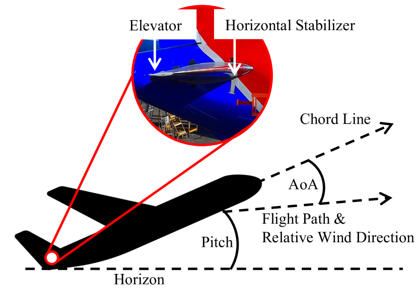
During the design of the 737-MAX line of aircraft, Boeing sought to certify it as a 737 variant to streamline the aircraft’s certification and to minimize the pilot training for airline companies. Compared to the 737-NG, the 737-MAX made a notable change from the CFM56 engine to the LEAP-1B engine, which is larger and placed farther forward. Testing revealed that in specific scenarios, the new engines could push the nose of the 737-MAX upward and cause the aircraft to stall due to a high Angle-of-Attack (AoA) (18∘). To address this issue, Boeing introduced MCAS, a flight stabilization program that automatically pitches the aircraft down to prevent a stall during high-AoA maneuvering.
In general, MCAS operates as follows. It first observes the AoA of the aircraft (see Fig. 1) through a sensor. In response to a high AoA, MCAS provides a 2.5∘ nose-down control input to the horizontal stabilizer (HS) to push the nose of the aircraft back down and avoid stall [14].
While initial disclosures to the FAA demonstrated an MCAS that was less intrusive to the flight controls (and deemed a low risk), Boeing failed to notify the FAA of substantial changes to MCAS and made no mention of MCAS in the 737-MAX’s pilot manuals. Because pilots were ill-prepared to handle an erroneously engaged MCAS, two deadly crashes followed: ET302 and JT610. While the 737-MAX is equipped with redundant AoA sensors, MCAS was designed to check only the AoA sensor located on the pilot-side. During these flights, the AoA sensor delivered faulty readings that made MCAS believe the airplane’s AoA was too high. Consequently, the nose of the aircraft was pushed down by MCAS. To counteract MCAS, the pilot manually trimmed the HS and pulled back on the column to actuate the elevator (see Fig. 1) to raise the nose back up. MCAS again displaced the HS due to the sensor’s incorrect readings. After back-and-forth between MCAS and the pilot, the HS was eventually displaced so much that elevator deflection could not counter the effects of the much larger HS. Also, due to aerodynamic factors, the manual HS hand-crank available in the cockpit eventually would not budge. In both catastrophic cases, the aircraft entered a steep nosedive and crashed. The two crashes killed all 346 people onboard and resulted in the grounding of all Boeing 737-MAX aircraft globally. While skilled pilots were sometimes capable of landing aircraft that MCAS negatively impacted, these instances were not reported to any regulatory agencies until after the deadly crashes [15].
In response to these crashes, Boeing proposed a redesigned MCAS with several changes [16]. First, MCAS will now check both AoA sensors. If the AoA sensors disagree when the flaps are not up, MCAS will not activate. Second, MCAS will only activate once per sensed event rather than an unconstrained number of times. Lastly, when MCAS does engage, pilots can now override MCAS and perform manual flight at any time since MCAS will not provide more input on the HS than the pilot can put on the elevator. The final revision approved by the FAA included a few additional requirements to the flight control computer, including integrity monitoring in order to stop erroneously generated trim commands from MCAS [17].
2.2 Boeing’s Inconsistent MCAS Design
There is an inconsistency in Boeing’s revisions:
-
•
Boeing originally designed MCAS due to a lack of trust for the pilot, defaulting to trusting the autonomous control of the aircraft through MCAS;
-
•
Boeing revised MCAS due to a lack of trust for autonomous control, defaulting to trusting the pilot control of the aircraft.
Such scenarios where both the autonomous entity and a human compete for control of a vehicle is called a semi-autonomous (SA) system. Defaulting control to one input in the case of disagreement is a common trend in SA system design. While Boeing designed both versions of MCAS with this default behavior, one can see cases where the pilot is more trustworthy and others where the MCAS is: there are instances in flight where either the pilot or the autonomous system could be incorrect. Thus, we argue that neither the original design nor the redesign is the right choice. To back this claim, we reconstruct the behavior of the pre- and post-crash MCAS using information The Seattle Times [14] and the FAA [17] reported to the public and conduct a preliminary analysis (Fig. 2). We find that the redesign, which fully trusts the pilot, introduces similar hazard as the original MCAS, which fully trusted the autonomous system, supporting our claim that neither design choice is the right one. We conclude that our preliminary result calls for a deeper analysis of scenarios that threaten either MCAS version.
A well-designed SA system should not default control to one input in the face of conflicting inputs. We use this initial insight to motivate the following research question:
In the remainder of this paper, we explore this question in the specific case of the MCAS in the Boeing 737-MAX.
3 Threat Model
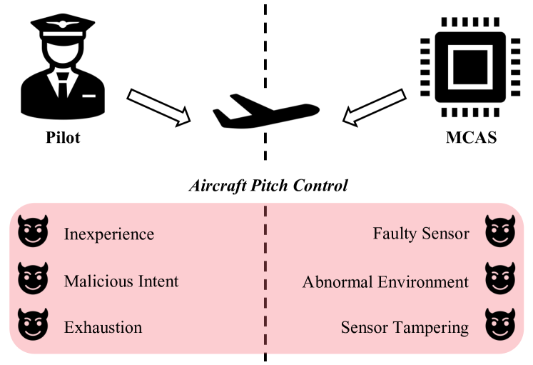
As demonstrated in § 2.2, pitch control of the aircraft is fallible through the input of either the autonomous MCAS or the human pilot. We provide an overview of this threat model in Fig. 3.
It is evident from the crashes of the 737-MAX aircraft that erroneous (or compromised) sensor readings are capable of eliciting behavior from the MCAS module that may put the vehicle into a dangerous state. In the case of the prior crashes, this is due to broken or damaged AoA sensors. However, erroneous sensor readings can also be caused by abnormal environmental conditions or intentional physical or digital tampering of the sensor values by an adversary. More recently, the cybersecurity of aircraft against remote adversaries has been questioned due to a takeover of the internal PA system on some American Airlines aircraft [18, 19]. Irrespective of the reason for erroneous sensor readings, they will cause the autonomous system to misunderstand the physical state of the vehicle, leading to incorrect and dangerous control decisions.
Likewise, human factors also provide possibility for dangerous control of SA systems. For instance, pilots with malicious intent can intentionally change the pitch of an aircraft to send it into a nosedive and crash, like the crash of Germanwings Flight 9525 [20]. There are reasons other than malicious intent for why a pilot could dangerously control the pitch of an aircraft, including inexperience and exhaustion.
Thus, when evaluating the threats to MCAS, four scenarios must be considered. In the first scenario, neither MCAS nor pilot input are providing dangerous control to the aircraft. For the second and third scenarios, either MCAS or pilot input are providing dangerous aircraft control. In the final case, both MCAS and pilot input are dangerously controlling the aircraft. In this paper, we focus on the first three scenarios, but discuss how we can leverage prior work to handle the last case in § 8.
Recall that MCAS was originally included in the 737-MAX to counter the inexperience of pilots who were trained to fly the 737-NG line of aircraft. While quick remedial action from an experienced pilot was possible [15], MCAS took an extreme form of distrust of pilot control, effectively ignoring the pilot’s attempt to undo the erroneous MCAS control. Conversely, the redesign of MCAS takes an extreme form of distrust of autonomous control, enabling the pilot to easily override MCAS.
4 Semi-Autonomous MCAS (SA-MCAS)
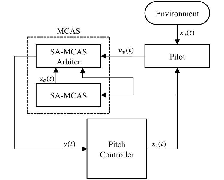
Following our preliminary analysis of the Boeing MCAS design before and after the 737-MAX crashes (Fig. 2), we propose Semi-Autonomous MCAS (SA-MCAS), an MCAS that does not give bias to one control input over the other. SA-MCAS uses an arbiter to cross-validate the sensor readings to first determine whether the pilot or autonomous control input is correct and then decide which to allow authority to control the pitch of the aircraft.
We provide an overview of the SA-MCAS control-loop in Fig. 4. During each iteration () of the control-loop, airplane sensor data () is delivered to SA-MCAS and indicators in the cockpit. Additionally, pilots use intuition and vision to infer additional information about their environment (). Using the available data, the pilot and SA-MCAS decide on their control input ( and , respectively). Then, the SA-MCAS arbiter determines which of the control input to be used to control the pitch of the aircraft. Finally, the resulting behavior () informs the pitch controller of a new state.
Challenges. To the best of our knowledge, SA-MCAS is the first to explore the consequences of the designs of the various 737-MAX MCAS revisions. As a result, during the development of SA-MCAS we encountered several challenges that lead to the primary contributions of this paper. Therefore, before returning to the research question posed in § 2.2, we first raise the following technical questions:
-
❶
How can we streamline the design and evaluation of MCAS programs? (§ 5)
-
❷
Which control inputs from MCAS and the human pilot threaten the safety of the aircraft? (§ 6)
-
❸
How can we detect incorrect/dangerous control input and subsequently mitigate it by changing the authority of control? (§ 7)
We answer these questions and evaluate the respective solutions in the following sections.
5 MCAS Simulation
In this section, we address Challenge❶. Using a real airplane as a testbed for evaluation of SA-MCAS is unrealistic/infeasible due to the high cost of purchasing the aircraft, renting or building a storage facility, and hiring pilots. Thus, the natural solution is to employ a widely-used flight simulation engine. Aerospace companies have custom flight simulators for testing their internal products, but they are often unavailable to researchers. As a result, open-source flight simulators, such as JSBSim [12], are popular among academic researchers. Such simulation tools have been vetted by NASA, validating their accuracy of modeling real flight maneuvers [21]. The JSBSim flight simulator gives us the ability to accurately model the Boeing 737 MAX’s flight and control dynamics. Furthermore, because of the ease of modeling control loops in MATLAB Simulink, an integration of JSBSim to MATLAB was developed for this purpose [22]. However, its functionality was limited to just a few hard-coded control inputs and no account for pilot control.
To overcome this issue of inflexibility, we introduce an extension to the JSBSim Simulink module, which includes several user-definable features. Our extension enables the user to select any flight sensor input/output to/from JSBSim, provides a pilot simulation module with customizable scripts for controlling the aircraft, and an MCAS module for easily integrating new MCAS designs. Furthermore, switching between scripts and different MCAS designs is programmable, allowing for automated simulation runs without any additional manual effort.
In addition to these features, we provide a module for injecting erroneous sensor readings into the JSBSim sensor data. This module is capable of injecting three different classes of erroneous data. First, sudden injection data, where the sensor data is set to a constant value. Second, delta injection data, where the sensor data is offset with a constant value. Third, gradual injection data, where the sensor data offset is determined by a function of time. A more rigorous definition for the erroneous data is available in § 6.1.
5.1 Simulation Creation Process
| Maneuver | Performed in Crash | Ref. |
| Accelerate | N/A | |
| Climb | [23] | |
| Descend | [23] | |
| Level-Turn | [24] | |
| Climb-Turn | [23, 24] | |
| Descend-Turn | [23, 24] | |
| Holding Pattern | [25] | |
| Takeoff | [26, 23] | |
| Landing | [23] |
We provide a tutorial on creating simulations in our toolkit. The process is split into three stages (Fig. 5).
-
1.
Initialize the input/output parameters. Before designing the rest of the simulation, you must define the data available. Our toolkit enables a user to define the flight sensor data s/he wants to have on each iteration of the simulation for use in other simulation components. This information is provided as part of an XML file. Also part of this step is defining the time ranges that erroneous input occurs and the characteristics of the erroneous input. This data is to be defined within a JSON file. We show code snippets of these in 5(a).
-
2.
Building the MCAS module. We next integrate a specified MCAS design into the simulation. Using output parameters from the previous step (which also may have been altered by the error injection portion), we define MCAS activation behavior when specific conditions are met. In 5(b) is a demonstration of an implementation of the pre-crash MCAS activation conditions.
-
3.
Scripting the pilot behavior. Finally, we provide several pilot flight maneuvers as part of the toolkit, such as takeoff, landing, and turning, and adding a new maneuver is straightforward (5(c)). Again, this requires output from the first step in order to activate behavior based on specific conditions. A limitation of this simulated approach is the simulated pilot lacks some of the finer feel and touch of a real-world pilot. However, we design these simulations using aircraft manuals that make suggestions for typical choices in flight (see the references in Tbl. I). Therefore, our simulation of pilot behavior is sufficient for investigating error injections and defense.
5.2 Example Simulation Scenarios
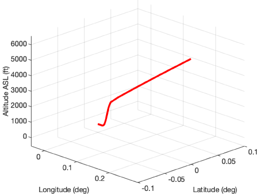
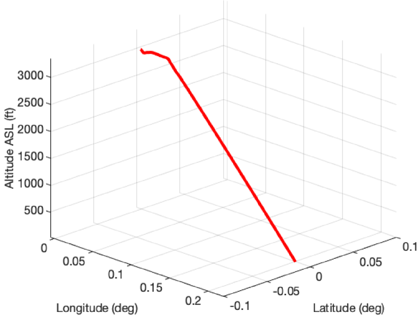
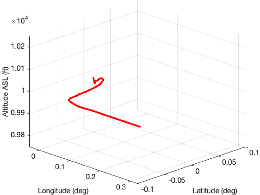
Using our toolkit, we present the simulation results for a few standard flight scenarios. A summary of the flight scenarios is available in Tbl. I. To validate our simulation accuracy, we graph the 3D trace of the aircraft, such as in Fig. 6.
The flying traces are shown to accurately draw the path of the desired maneuver. For the purpose of evaluating MCAS, the takeoff and landing maneuvers are the most important, as they are the intended scenarios for MCAS activation. However, we simulate other maneuvers to verify that MCAS will not activate when it is unneeded.
Furthermore, we demonstrate the effect of injected errors to the AoA sensor on the flight path, as seen in the preliminary study presented in Fig. 2. This result also demonstrates the Boeing’s implementation of MCAS pre- and post-crash. In the next section, we will detail novel MCAS failures.
6 Launching Attacks on MCAS
Using the erroneous sensor injection tool included as part of our simulation toolkit presented in § 5, we launch attacks on MCAS to reveal novel vectors for causing dangerous control of the aircraft. Doing so leads to a conclusion for Challenge❷. To lay the groundwork for the remainder of this section, we provide definitions for each of our injection methods. Then, before performing a more rigorous analysis of possible injection scenarios, we demonstrate the case study crash of JT610.
6.1 Methodology for Launching an Attack
We describe the methodology for launching our attacks which are divided into two categories: injected sensor values and dangerous pilot behavior. While our threat model in Fig. 3 is more abstract in its representation of these attacks, we showcase a more specific example of sensor anomalies through our simulations called sensor error injections. Injecting simulated errors into the sensor data streams is similar to how either natural sensor failures or adversarial attacks would occur.
6.1.1 Sensor Error Injection
Each erroneous data is injected in a unique way and thus requires its own evaluation criterion. We use to denote the airplane sensor data at time in a time series, and to denote the erroneous airplane sensor data at the same time . Since we are considering the particular case of MCAS, we can further simplify to include the left and right AoA sensor readings.
Sudden Injection
A sudden injection is defined as
| (1) |
where is a predefined constant value. This injection is agnostic of the current sensor value, making it the most simple sensor injection. For our evaluation, we seek to determine the values of that are capable of causing dangerous flight behavior. The erroneous data from the AoA sensor in ET302 was due to a sudden injection.
Delta Injection
For a delta injection, we again assume a predefined constant value , characterizing the injection as
| (2) |
The delta injection is one step from the sudden injection, adding the constant value to the existing sensor data. The evaluation of the delta injection must consider the combinations of airplane state and values of that are capable of eliciting a dangerous mode of flight. The erroneous data from the AoA sensor in JT610 was due to a delta injection.
Gradual Injection
The gradual injection is the most sophisticated of the three, using a function to launch the erroneous injection. Taking a final step from the delta injection, a gradual injection replaces with :
| (3) |
Furthermore, compared to the delta injection, the -intercept of the function is replaced with the sensor value at the start of the injection, . While the function can be any function, we choose a few standard functions: the linear (), quadratic (), and logarithmic () functions, where and are predefined coefficients. This error injection mirrors how a drifting sensor failure may occur over time, or how a stealthy adversary may inject error into a sensor data stream.
A gradual injection has an additional component just before the injection concludes. The injection gradually recovers to the original sensor value by a two-stage process. First, we move the injected value by 5% in the direction of the real sensor value at each time step. Then, once we are within 10% of the original difference of the injected sensor at the start of recovery and the original sensor at that same point in time, we move on to the second stage where we use a Kalman filter to ease into the real sensor value. More details of this algorithm can be found in Alg. 1.
6.1.2 Dangerous Pilot Behavior
The scope of MCAS’s authority for counteracting pilot control is exclusively within the pitch axis of the aircraft in the downward direction. The pilot controls the pitch by either manually cranking the HS or pulling up or pushing down on the control column to adjust the elevator. The longitudinal flight dynamics equation using the short period approximation is [27]:
| (4) |
where is the rate of change in altitude, is the rate of change of the pitch, and are flight system transition and control distribution matrices, respectively, and is the elevator input.
To provide dangerous control input to the aircraft within the range of command of MCAS, the pilot would need to continuously pitch the aircraft up. They do so by pulling back the control column, which in turn commands a consistent input to . Eventually, the AoA of the aircraft will exceed 18∘, causing the aircraft to stall and experience a significant decline in altitude before entering a nosedive.
6.2 Case Study: Simulation of JT610
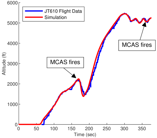
In order to understand how injections impacted the real flight on JT610, we model the delta injection that impacted the MCAS decision-making. The flight-data recorder (black box) for JT610 was successfully found by the Indonesian government, and while the raw data was never publicly released, detailed graphs of the data are available for analysis [28, 15]. We use the pilot simulation framework described in § 5 to model the decisions made by the pilots in JT610, following the same takeoff procedure. Likewise, we modeled the same AoA delta injection that the left AoA sensor faced, which had for the entire flight from takeoff until crash. Before takeoff, the injection in the left AoA sensor was more variable, but because it was before takeoff it did not impact the operation of the airplane. Thus, we do not model this in our simulation.
As mentioned before, the black box data from JT610 was never publicly released, but we were able to acquire the flight path of JT610 from Flightradar24 [29]. We overlay this recovered data with our simulation of JT610 in Fig. 7. The overlay on the simulation demonstrates the capability of our toolkit to accurately model MCAS misfires in the presence of incorrect sensor values. The simulation is shown to closely overlap with the true flight path of JT610. Since we are capable of providing an accurate simulation of real piloting of aircraft experiencing injection attacks, we provide a deeper investigation of how our proposed injection attacks impact the simulated aircraft in the following section.
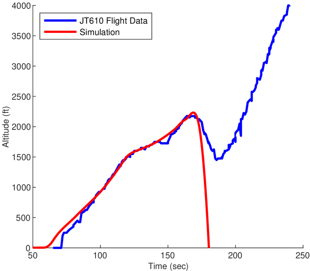
Before conducting this deeper investigation, our case study reveals a more interesting pattern that warrants a closer inspection. The pilot of JT610 was capable of maintaining an altitude of 5250 ft. for 7 mins. If an immediate action was not taken by the pilot, JT610 would have entered a nosedive almost immediately (simulated in Fig. 8). In fact, the pilot recovered the aircraft 21 times in a row before becoming overwhelmed and handing off responsibility to the co-pilot, who ultimately failed to recover the aircraft after the hand-off. Ultimately, the crash of JT610 was a combination of MCAS repeatedly activating and the pilot becoming too tired to manually fight against MCAS automatically trimming the HS. In other words, this case study underscores the pilot’s capability of manually recovering an aircraft from rare false-positive activation of MCAS.
6.3 Evaluation of Proposed Attacks
To conduct experiments on the different types of sensor threats, we perform a parametric analysis using the sensor error injection format in 5(a). For a given injection type, we keep all inputs to the injection format constant except one, which is the value we target for each analysis.
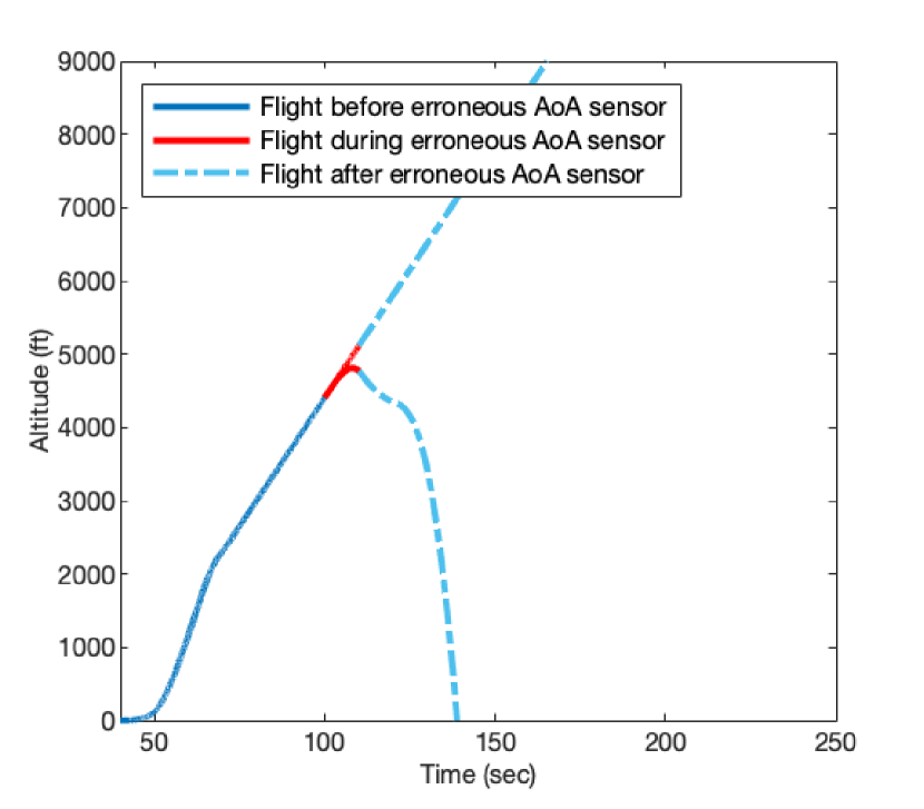
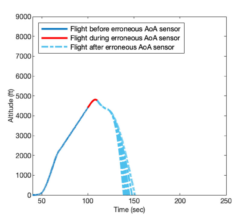
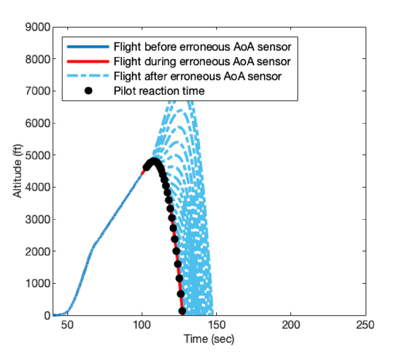
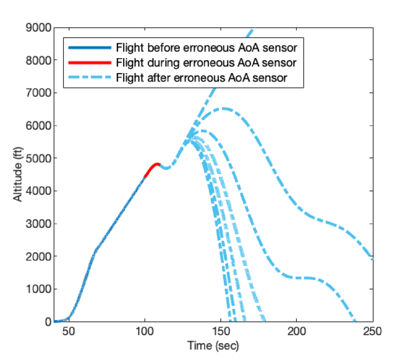
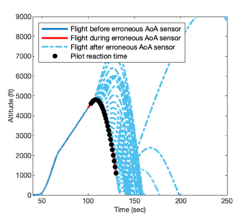
6.3.1 Sudden & Delta Injections
For the sudden and delta injections, we conduct three experiments for each injection: (1) StartTime=100, EndTime=130, and Val set from 0 to 30; (2) StartTime=100, Val=18, and EndTime set from 110 to 180. In experiments (1) and (2), the pilot reacts after 10 secs; (3) StartTime=100, EndTime=130, and Val=18, and the pilot’s reaction set from 3 to 30 secs. The pilot’s reaction is a normalized elevator input of -0.3, followed by a normalized elevator input of -0.15 after 10 more secs. In each of the three experiments, the original MCAS is used, and the range of values for the variable has an increment of 1. The results of these simulations for the sudden and delta injections are summarized in Fig. 9 and Fig. 10, respectively.
The results for the sudden injection demonstrate that even just exceeding the threshold of MCAS is enough to trigger devastating impact. This is especially apparent in 9(a), which has two distinct outcomes for the plane. The parametric analyses of EndTime and pilot reaction time show that these variables impact the time-to-crash (Figs. 9(b) and 9(c)).
On the contrary, the results for the delta injection show something more interesting, especially around the threshold of MCAS activation. For instance, the analysis of Val in 10(a) shows that there are some recoverable scenarios of an MCAS misfire. In the case of 10(b), a smaller EndTime can illicit either a recoverable flight or a slower descent after an MCAS misfire. Finally, the pilot reaction time analysis demonstrates an interesting pattern. As shown in 10(c), a later reaction can allow the pilot to deflect the aircraft’s decent into a more graceful crash of the aircraft, whereas an earlier reaction time may trigger an additional MCAS misfire and quickly push the aircraft back into a quick decent.
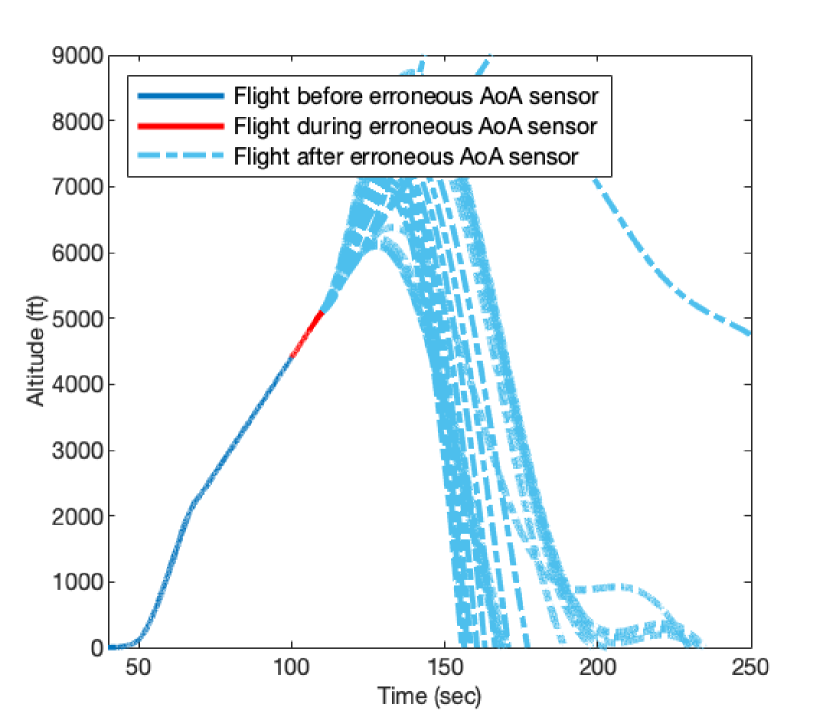
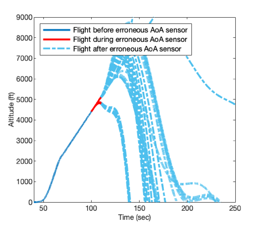

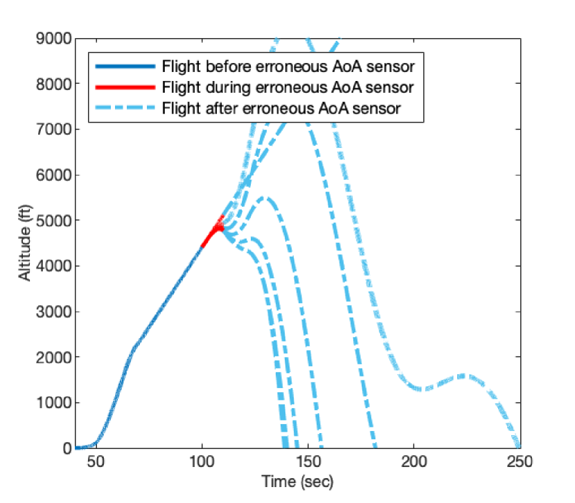
6.3.2 Gradual Injections
For the gradual injections, we conduct three experiments, one for each of linear, quadratic, and logarithmic functions. The controlled settings for these experiments are StartTime=100, EndTime=130, and pilot reaction time of 10 secs for the linear and quadratic simulations, and 22.5 secs for the logarithmic simulations. Coef1 is the coefficient in each of the three functions, and Coef2 is the coefficient in the quadratic function. For the linear function, we run simulations with Coef1=0 to 3 with a step size of 0.1. For the quadratic function, Coef1=0 to 1 and Coef2=0 to 3, both with step sizes of 0.1. And for the logarithmic function, Coef1=0 to 200 with a step size of 1. The pilot reaction works the same as in § 6.3.1, and the original MCAS is used. The results of simulations are summarized in Fig. 11.
The gradual linear injections lead to three behaviors that we notice (11(a)). For the smaller values of Coef1, the impact is marginal or causes a very slow descent. As Coef1>1, we see the flight trajectory either nosedive completely or nosedive into a last second nose up before ultimately crashing. In the latter, it appears that a more graceful landing is possible in comparison to a nosedive.
In the case of the gradual logarithmic injection (11(c)), the flight descends quicker for larger values of Coef1. In the case of smaller values, the descent is more gradual, whereas larger values lead to a nose dive.
We break down the gradual quadratic injection simulations based on Coef1, shown in Fig. 12. The breakdown shows that starting from Coef1=0 (12(a)), the gradual quadratic injection starts with the behavior of the linear function (11(a)). With progressive increases in Coef1 (Figs. 12(b) and 12(c)), the gradual quadratic injections converge toward the behavior of a sudden injection (9(a)). An adversary may benefit from a gradual quadratic injection in order to achieve similar results as the sudden injection without exhibiting an immediate “sudden” jump to the target value.
| Maneuver | Parameter(s) Adjusted | # Collected | Mission Success Metric(s) |
| Accelerate | Initial airspeed (kts) Final airspeed (kts) | 121 | Maintain level altitude ( ft) |
| Climb | Initial altitude (ft) Final altitude (ft) | 100 | Maintain acceptable g-force ( and ) Maintain level altitude along expected route ( ft) |
| Descend | Initial altitude (ft) Final altitude (ft) | 100 | Maintain acceptable g-force ( and ) Maintain level altitude along expected route ( ft) |
| Level-Turn | Initial heading (∘) Turn amount (∘) | 101 | Maintain level altitude ( ft) |
| Climb-Turn | Turn amount (∘) Climb amount (ft) | 121 | Maintain acceptable g-force ( and ) Maintain level altitude along expected route ( ft) |
| Descend-Turn | Turn amount (∘) Climb amount (ft) | 121 | Maintain acceptable g-force ( and ) Maintain level altitude along expected route ( ft) |
| Holding Pattern | Initial heading (∘) Inbound/outbound leg time (s) | 169 | Maintain level altitude ( ft) |
| Takeoff | Initial climb airspeed (kt) Climb phase transition altitude (ft) Final climb airspeed (kt) Final altitude (ft) | 225 | Maintain an altitude Continue to increase in altitude |
| Landing | Initial altitude (ft) Vertical descent rate (ft/s) Approach airspeed (kt) | 100 | Reaches ft with safe landing conditions (pitch ; airspeed 120 kt) |
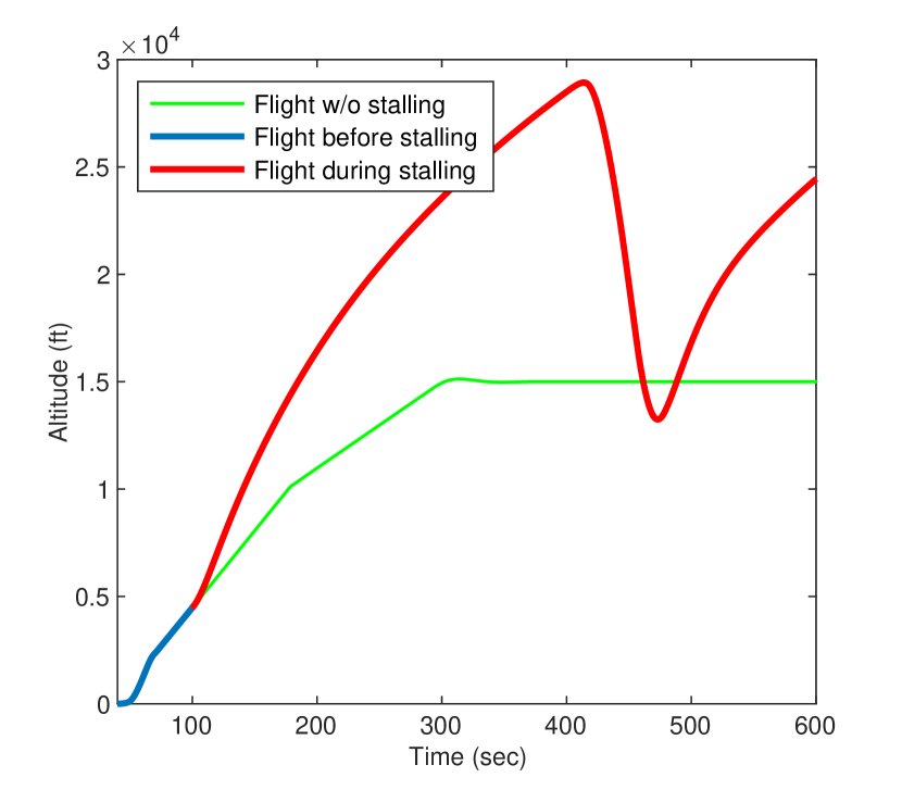
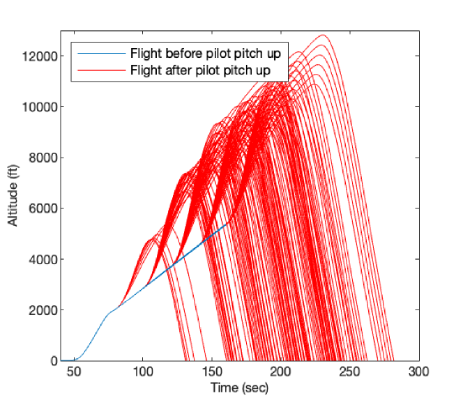
6.3.3 Pilot Dangerously Stalls Aircraft
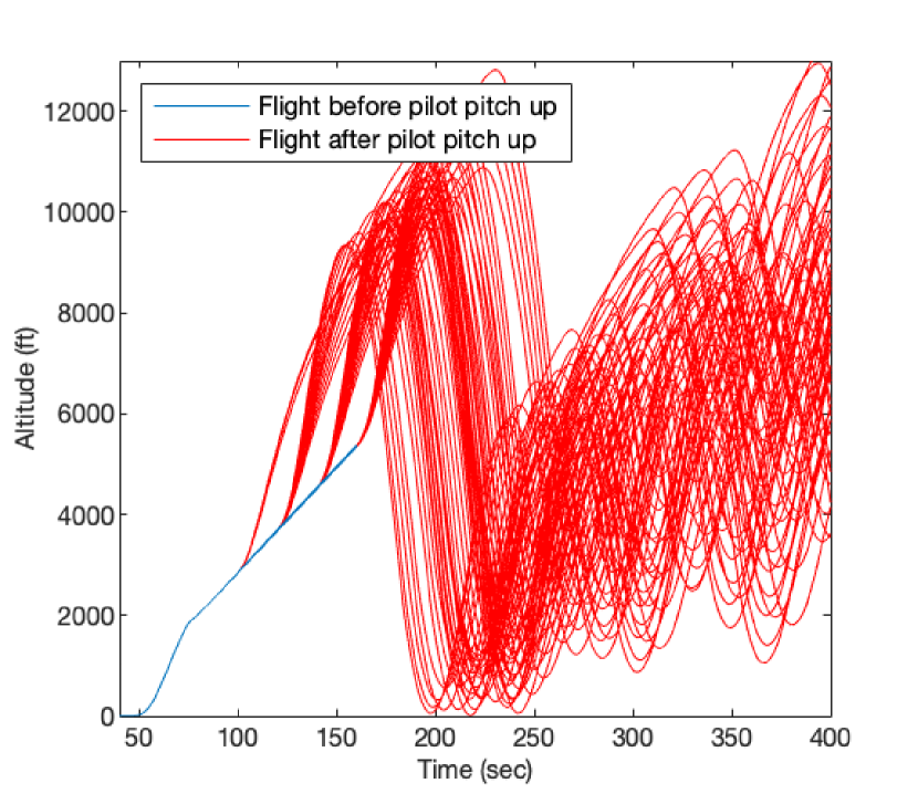
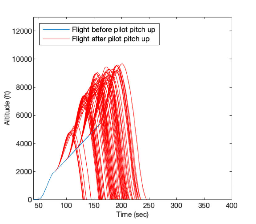
In our final experiment on launching attacks on the MCAS, we take the other side and simulate a pilot attempting to dangerously stall out the aircraft equipped with the post-crash MCAS. Our findings are summarized in Fig. 13. In our simulations, we control three parts of the pilot: the pitch the pilot targets (from 25∘ to 50∘ in increments of 5), the final climb airspeed (from 225kt to 275kt in increments of 10), and the pitch up start time (from 80 sec. to 160 sec. in increments of 20). As is clear in Fig. 13, all simulations lead to a stall and ultimately crash the aircraft through the subsequent nosedive.
7 SA-MCAS Arbiter
With an available simulator for streamlining the design and evaluation of MCAS programs (§ 5) and well-defined threat scenarios (§ 6), we must consider a defense for preventing dangerous control input. Here, we discuss and evaluate our implementation of the control arbiter in Fig. 4. In doing so, we seek a conclusive answer to Challenge❸.
7.1 Training & Testing Dataset
To our knowledge, there is no dataset robust enough for the purpose of our evaluation. Specifically, we require a dataset that not only includes flight sensor data for all of the standard flight maneuvers in Tbl. I, but also maneuvers that experience dangerous control.
The dataset our toolkit produced is summarized in Tbl. II. Because MCAS is activated during stall conditions, which are most likely to occur during takeoff and landing, we focus much of our attention on takeoff and landing maneuvers. We generated takeoff maneuvers where the aircraft first ascends rapidly during initial climb, then climbs more gradually after reaching a specified altitude. The aircraft continues to climb until it arrives at a final cruising altitude, where it remains at level flight. As for landing maneuvers, the aircraft starts at an initial altitude and begins descending at a consistent vertical speed. The aircraft reduces its speed to a target speed, and maintains steady descent. Actual touchdown of the aircraft is unnecessary since MCAS plays no role at this point, so simulations are terminated upon reaching a very low altitude. These takeoff and landing procedures are performed many times, with several key parameters modified (Tbl. II).
In total, we simulated and collected data from 1158 flights, totaling 133 simulated flight hours.
7.2 Model Architecture
For the SA-MCAS arbiter, we opt to use a series of trained linear regression models, each representing a correlated sensor pair. Then, the estimated value from each regression model is compared against the actual measured value. For each comparison, if the difference between the two values is within a trained , then we deem the sensor measurement to accurately measure the environment. Otherwise, the pair is flagged for additional inspection. For the regression estimates that do not match the measured value, we use several correlated sensor pairs to pin down exactly which sensor of the flagged pair is causing the inaccurate estimate.
To determine the correlated sensor pairs and train the linear regression model, we use the dataset described in Tbl. II. During the training, we exclude the data with sensor injections and dangerous pilot control that we generated in § 6. This is because the goal for the regression models is to understand normal control input for correlated sensor pairs in order to later infer when a particular control decision is normal. Of the data in Tbl. II, we split 30% for training and 70% for testing, where we split randomly between each maneuver type in order to have equal representation.
7.2.1 Correlated Sensor Pairs
Using our dataset summarized in Tbl. II, we determine correlated pairs of sensed data across each flight maneuver as well as all maneuvers as a whole. Our findings for all maneuvers as a whole are summarized in Tbl. III. We automatically drop pairs of sensors that have an absolute correlation 0.8. We additionally use a relationship between the AoA and pitch due to their values being closely coupled with one another.
| Sensor #1 | Sensor #2 | Corr. Val. |
| Altitude | Temperature | -0.85 |
| Altitude | Air pressure | -0.99 |
| Altitude | Pitch | -0.98 |
| Altitude | acceleration | 0.81 |
| Pitch | acceleration | 0.86 |
| Roll | Heading | 0.95 |
| Roll | Yaw acceleration | 0.94 |
| acceleration | Engine % | 0.87 |
| acceleration | Throttle | 0.86 |
| acceleration | Roll acceleration | -0.80 |
| Engine % | Throttle | 0.95 |
| Temperature | Air pressure | 0.91 |
7.3 Metrics for Evaluation
During the evaluation of the SA-MCAS arbiter, our metric of concern is primarily of overall flight safety. In other words, after injecting erroneous data or commanding the pilot to perform a dangerous control input, we are most concerned with whether SA-MCAS intervenes to prevent the simulated flight from crashing. As we show in our preliminary study in Fig. 2, the individual MCAS versions are capable of preventing separate dangerous control, but our evaluation seeks to prevent both.
Thus, an important aspect to our evaluation is whether, ultimately, the aircraft safely finishes its mission. Here, we define “mission” to mean the duration of any particular maneuver, but a more precise definition would mean the journey of an airplane from takeoff to landing. Since the latter definition is too general, we use the former definition to provide a more fine-grained assessment of each type of dangerous control that we studied in § 6. In doing so, we provide a rigorous argument for the success of SA-MCAS. To clarify what it means for a mission to finish successfully, we provide metrics for distinguishing success from failure for each maneuver, included in Tbl. II.
7.4 Evaluation of SA-MCAS Arbiter’s Prevention of Dangerous Control
We evaluate the SA-MCAS arbiter. Using our design (§ 7.2), we train linear regression models for each sensor pair in Tbl. III, as well as a linear regression for the relationship between the pitch and the AoA of the aircraft. During simulation of flights, we use these regression models to take one value of a correlated sensor pair to estimate the other value. Then, we determine the validity of the measured sensors using the estimated sensors.
To validate the AoA sensors for use by MCAS, we specifically estimate the pitch of the aircraft with the change in altitude of the aircraft to verify if the pitch is normal. We use the pitch to estimate the AoA of the aircraft to verify if the AoA is normal. Additional sensor pairs can be leveraged to increase the trust in our estimations.
7.4.1 Sensor Error Injection
For sensor error injections of any type (i.e., sudden, delta, or gradual injections), the SA-MCAS arbiter delivers the correct control of the aircraft’s HS in every single modeled injection scenario that we report in § 6.3.1 and § 6.3.2. In other words, SA-MCAS arbiter is able to perfectly account for when the AoA sensor is exhibiting behavior that would lead to dangerous control of the aircraft and prevents it from doing so.
| Pitch Up Time | # Success / # Total |
| 80 sec. | 0/36 |
| 100 sec. | 5/36 |
| 120 sec. | 14/36 |
| 140 sec. | 21/36 |
| 160 sec. | 28/36 |
7.4.2 Dangerous Pilot Behavior
To evaluate the SA-MCAS arbiter on dangerous pilot behavior, we reuse our simulated pilot maneuvers from § 6.3.3. In this case, not all simulated flights were recoverable. We separate the flights based on whether they were recovered in Fig. 14. While overall just 68/180 flights were recovered, a breakdown of the pilot behavior scenarios reveals the shortcomings of the SA-MCAS arbiter. If we break down the 180 simulated flights based on when the pilot starts to pitch up the aircraft into a stall (Tbl. IV), the odds of flight recovery increase as the pitch up time increases. This is primarily because the aircraft gains more altitude with more time before the pitch up into a stall. A common mantra in the aeronautics industry is that “altitude is life insurance,” and this certainly holds here.
While their impact is less than the pitch up time, the target pitch and final climb airspeed also both impact SA-MCAS’s ability to recover the aircraft from dangerous flight behavior. For instance, a large target pitch may put the aircraft into such an extreme stall that the aircraft is doomed from the start. Since MCAS only controls the HS and has no authority over the elevator, there is nothing the SA-MCAS arbiter can do to stop the pilot from dangerously pulling back the column to control the elevator.
8 Discussion
8.1 Other Attacks
There are a few additional attacks that we would like to discuss further.
8.1.1 Instantaneous Injection of Incorrect Sensor Values
The instantaneous injection creates incorrect values at singular points in a sensor’s readings. These sort of injections can either be periodic or random in their behavior. While we do not evaluate these here, SA-MCAS assess each individual sensor value. During our evaluation of the three main injections in this paper, no singular erroneous sensor value was missed by SA-MCAS.
8.1.2 Pilot Provides Dangerous Nosedive Input
Our evaluation of dangerous pilot input only assesses a pilot attempting to stall the aircraft, as this is the intended scenario for MCAS to activate. In other words, MCAS is not equipped to detect dangerous nose-down events and mitigate them. Thus, our evaluation did not cover this dangerous input. However, given that MCAS does have the ability to control the HS of an aircraft, it is possible that it could be given the authority to control the HS for dangerous nose-down events. In such a case, SA-MCAS arbiter may be used to counteract such an event and in order to stop the aircraft from entering a nosedive.
8.1.3 Both Control Inputs are Erroneous
We evaluated the cases where either the pilot delivers dangerous manual control to the aircraft or the MCAS delivers unsafe autonomous control to the aircraft. What we did not evaluate is what happens when both of these inputs are unsafe. A limitation to the current version of SA-MCAS is that at least one of the control modes must be delivering safe control input. The problem of delivering safe control to an SA system where all actors/operators are attempting dangerous control has been studied in other, simpler domains. For instance, one can design an SA system where we have full knowledge of its state-space. Then, we may only allow control of the SA system along state-space paths that guarantee its safety [30]. However, for more sophisticated systems such as aircraft, providing a complete state-space is intractable due to the exploding number of states one can generate. To alleviate this issue, the prior work loosened the guarantees provided to the safety of the system in favor of a probabilistic approach to safe operation [31, 32, 33]. Rather than generating the entire state-space, just a few important sections of the state-space are generated. During operation, the paths with the highest probability of safe operation are favored over those with lower probabilities of safe operation.
In our case, these solutions are complimentary to the desired objective of SA-MCAS. To extend them to our work, we may define a set of safe states for the airplane to wait (such as the holding pattern) while the SA-MCAS arbiter determines the correct course of action. Then, in order to make the correct, safe control decision, we may use prior work on local view reconstruction to rebuild the erroneous sensor data into the form that is most probably correct [34]. This option is the last resort and undesirable if we are capable of using a safe control decision that is directly from either the pilot or MCAS.
8.2 Limitations
Below we discuss limitations to our work and potential directions for addressing them. We also discuss the trade-offs and provide alternative choices for when SA-MCAS’s trade-offs are insufficient for a certain user. For the cases where iterative improvements may be available, we leave these possible extensions to SA-MCAS as future work.
Dangerous Pilot Input Prevention is Effective in a Limited Scope of Conditions. As we briefly allude to in § 7.4.2, there are a limited scope of conditions that SA-MCAS arbiter is incapable of recovering an aircraft from dangerous input. Generally, these simulations occur at a much lower altitude. While one solution would be to prevent the pilot from providing a dangerous control input on the elevator in addition to the HS, the MCAS is not given authority over the elevator. To do this would require FAA approval. Thus, a limitation of SA-MCAS is that these dangerous pilot controls are out of the scope of its capabilities.
Passenger Trust. In the aftermath of the Boeing 737-MAX crashes, passenger trust towards the 737-MAX aircraft has slowly recovered. The main contributor to this revival of faith has been from dropping MCAS as a tool that is capable of having authority to autonomously control the pitch of the aircraft. One drawback to our work is that it assumes that we can regain the trust of such passengers with a dynamic authority SA-MCAS. However, we note that the airline industry is not the only one facing this challenge—the autonomous vehicle industry has faced several controversies due to issues in the self-driving algorithms that lead to deadly accidents [35, 36].
While restoring public trust in autonomous systems is outside the scope of this paper, we acknowledge the drawback that this issue presents to SA-MCAS. In order to regain this trust, we propose that a system such as SA-MCAS should be introduced in such a way that would (1) educate the pilot on its autonomous functions and limitations so the pilot will not over-trust the SA system, and (2) give the pilot the capability to disable SA-MCAS in the event that issues with the algorithm arise. Before ever being put into the air, SA-MCAS should also go through hundreds of simulated flight hours with real pilots in order to establish faith with regulation agencies such as the FAA.
9 Conclusion
In this paper, we introduced SA-MCAS arbiter, a system for deciding who to trust when a human pilot and the autonomous MCAS module of the Boeing 737-MAX are in disagreement. Our analysis of the control threats of the post- and pre-crash MCAS version motivate the need for an MCAS that can make such dynamic control arbitration. We demonstrate SA-MCAS arbiter is capable of providing the correct control input in all cases of injected erroneous sensor values as well as many instances of dangerous pilot behavior, especially at a high altitude. Our results encourage recommendations toward Boeing to include a system such as SA-MCAS as an integrity checker in the flight control computer of the Boeing 737-MAX and other aircraft in order to achieve the FAA’s flight directive in [17].
References
- [1] V. A. Shia, Y. Gao, R. Vasudevan, K. D. Campbell, T. Lin, F. Borrelli, and R. Bajcsy, “Semiautonomous vehicular control using driver modeling,” IEEE Transactions on Intelligent Transportation Systems, vol. 15, no. 6, pp. 2696–2709, 2014.
- [2] A. Gray, Y. Gao, J. K. Hedrick, and F. Borrelli, “Robust predictive control for semi-autonomous vehicles with an uncertain driver model,” in 2013 IEEE Intelligent Vehicles Symposium, ser. IV ’13. Gold Coast, Australia: IEEE, 2013, pp. 208–213.
- [3] T. Weiskircher, Q. Wang, and B. Ayalew, “Predictive guidance and control framework for (semi-)autonomous vehicles in public traffic,” IEEE Transactions on Control Systems Technology, vol. 25, no. 6, pp. 2034–2046, 2017.
- [4] R. Rajamani and C. Zhu, “Semi-autonomous adaptive cruise control systems,” IEEE Transactions on Vehicular Technology, vol. 51, no. 5, pp. 1186–1192, 2002.
- [5] F. Altché, X. Qian, and A. de La Fortelle, “An algorithm for supervised driving of cooperative semi-autonomous vehicles,” IEEE Transactions on Intelligent Transportation Systems, vol. 18, no. 12, pp. 3527–3539, 2017.
- [6] R. Vasudevan, V. Shia, Y. Gao, R. Cervera-Navarro, R. Bajcsy, and F. Borrelli, “Safe semi-autonomous control with enhanced driver modeling,” in 2012 American Control Conference, ser. ACC ’12. Montréal, Canada: IEEE, 2012, pp. 2896–2903.
- [7] M. Huang, W. Gao, Y. Wang, and Z.-P. Jiang, “Data-driven shared steering control of semi-autonomous vehicles,” IEEE Transactions on Human-Machine Systems, vol. 49, no. 4, pp. 350–361, 2019.
- [8] A.-T. Nguyen, J. J. Rath, C. Lv, T.-M. Guerra, and J. Lauber, “Human-machine shared driving control for semi-autonomous vehicles using level of cooperativeness,” Sensors, vol. 21, no. 14, pp. 1–20, 2021.
- [9] S. J. Anderson, S. B. Karumanchi, , and K. Iagnemma, “Constraint-based planning and control for safe, semi-autonomous operation of vehicles,” in 2012 IEEE Intelligent Vehicles Symposium, ser. IV ’12. Alcalá de Henares, Spain: IEEE, 2012, pp. 383–388.
- [10] K. H. Wray, L. Pineda, and S. Zilberstein, “Hierarchical approach to transfer of control in semi-autonomous systems,” in Proceedings of the 15th International Conference on Autonomous Agents and Multiagent Systems, ser. AAMAS ’16. Singapore, Singapore: ACM, 2016, pp. 1285–1286.
- [11] F. van Wyk, A. Khojandi, and N. Masoud, “Optimal switching policy between driving entities in semi-autonomous vehicles,” Transportation Research Part C: Emerging Technologies, vol. 114, no. 2020, pp. 517–531, 2020.
- [12] J. Berndt, “Jsbsim: An open source flight dynamics model in c++,” in AIAA Modeling and Simulation Technologies Conference and Exhibit, ser. MMST ’05. Providence, Rhode Island: AIAA, 2004, pp. 1–27.
- [13] J. Crowley, “New southwest 737-800 without company name on the tail,” 2017. [Online]. Available: https://web.archive.org/web/20190117044404/https://www.flickr.com/photos/archivist/32413717542/
- [14] D. Gates and M. Baker, “The inside story of mcas: How boeing’s 737 max system gained power and lost safeguards,” The Seattle Times, 2019. [Online]. Available: https://www.seattletimes.com/seattle-news/times-watchdog/the-inside-story-of-mcas-how-boeings-737-max-system-gained-power-and-lost-safeguards/
- [15] S. Tjahjono, “Preliminary KNKT.18.10.35.04 aircraft accident investigation report,” National Transportation Safety Committee of Indonesia, Tech. Rep., 2018. [Online]. Available: http://knkt.dephub.go.id/knkt/ntsc_aviation/baru/pre/2018/2018%20-%20035%20-%20PK-LQP%20Preliminary%20Report.pdf
- [16] Boeing. (2019) 737 max software update. The Boeing Company. [Online]. Available: https://www.boeing.com/commercial/737max/737-max-software-updates.page
- [17] Federal Aviation Administration, “Airworthiness directives; the boeing company airplanes,” Federal Register, vol. 85, no. 225, pp. 74 560–74 593, 2020. [Online]. Available: https://www.federalregister.gov/d/2020-25844
- [18] A. Baio, “A mysterious voice is haunting american airlines’ in-flight announcements and nobody knows how,” Waxy.org, 2022. [Online]. Available: https://waxy.org/2022/09/a-mysterious-voice-is-haunting-american-airlines-in-flight-announcements-and-nobody-knows-how/
- [19] A. E. Petri, “This is not your captain speaking: Moans and groans are taking over some flights’ p.a. systems,” Los Angeles Times, 2022. [Online]. Available: https://www.latimes.com/california/story/2022-09-24/moans-groans-taking-over-some-american-airlines-flight-intercoms
- [20] Bureau of Enquiry and Analysis for Civil Aviation Safety, “Accident to the airbus a320-211, registered d-aipx and operated by germanwings, flight gwi18g, on 03/24/15 at prads-haute-bléone: Final report,” BEA Safety Investigations, Tech. Rep., 2015. [Online]. Available: https://bea.aero/fileadmin/uploads/tx_elyextendttnews/BEA2015-0125.en-LR_10.pdf
- [21] E. B. Jackson, M. M. Madden, R. Shelton, A. A. Jackson, M. P. Castro, D. M. Noble, C. J. Zimmerman, J. D. Shidner, J. P. White, S. Dutta, E. M. Queen, R. W. Powell, W. A. Sellers, S. A. Striepe, J. Aguirre, N. Vuong, S. E. Reardon, M. J. Weinstein, W. Chung, and J. S. Berndt, “Further development of verification check-cases for six-degree-of-freedom flight vehicle simulations,” in AIAA Modeling and Simulation Technologies Conference, ser. MMST ’15. Kissimmee, Florida: AIAA, 2015, pp. 1–34.
- [22] T. Sikström, “Flight simulator integration in test rig,” Master’s thesis, Royal Institute of Technology, 2021.
- [23] M. Křepelka. (2022) Boeing 737–800 flight notes. Krepelka.com. [Online]. Available: https://krepelka.com/fsweb/learningcenter/aircraft/flightnotesboeing737-800.htm
- [24] Professional Pilots Rumor Network. (2010) Built-in bank angle limits. Professional Pilots Rumor Network. [Online]. Available: https://www.pprune.org/tech-log/416502-built-bank-angle-limits.html
- [25] Federal Aviation Administration. (2022) Enr 1.5 holding, approach, and departure procedures. Federal Aviation Administration. [Online]. Available: https://www.faa.gov/air_traffic/publications/atpubs/aip_html/part2_enr_section_1.5.html
- [26] I. D. Williams. (2021) Boeing 737-800 takeoff procedure (simplified). FLAPS 2 APPROACH. [Online]. Available: https://www.flaps2approach.com/journal/2014/8/4/boeing-737-800-takeoff-procedure-simplified.html
- [27] J. P. How, “Lecture notes in 16.333: Aircraft stability and control,” Fall 2004.
- [28] National Transportation Safety Committee of Indonesia, “Accident boeing 737 max 8, pk-lqp (lni610),” 2018. [Online]. Available: https://ngamotu.nz/images/20181122-jt610-knkt.pdf
- [29] I. Petchenik. (2018) Jt610 granular ads-b data. Flightradar24. [Online]. Available: https://www.flightradar24.com/blog/wp-content/uploads/2018/10/JT610_Granular_ADSB_Data.csv
- [30] D. J. Musliner, E. H. Durfee, and K. G. Shin, “World modeling for the dynamic construction of real-time control plans,” Artificial Intelligence, vol. 76, no. 1, pp. 83–127, 1995.
- [31] E. M. Atkins, T. F. Abdelzaher, K. G. Shin, and E. H. Durfee, “Planning and resource allocation for hard real-time, fault-tolerant plan execution,” in Proceedings of the Third Annual Conference on Autonomous Agents, ser. AGENTS ’99. Seattle, Washington: ACM, 1999, pp. 244–251.
- [32] E. M. Atkins, E. H. Durfee, and K. G. Shin, “Detecting and reacting to unplanned-for world states,” in 1996 Fall AAAI Symposium on Plan Execution, Problems and Issues. Portland, Oregon: AAAI, 1996, pp. 571–576.
- [33] ——, “Plan development using local probabilistic models,” in Proceedings of the 12th Conference on Uncertainty in Artificial Intelligence, ser. UAI ’96. Portland, Oregon: AAAI, 1996, pp. 49–56.
- [34] C.-Y. Chen, “Context-aware detection and resolution of data anomalies for semi-autonomous cyber-physical systems,” Ph.D. dissertation, University of Michigan, 2022.
- [35] National Highway Traffic Safety Administration. (2021) Nhtsa orders crash reporting for vehicles equipped with advanced driver assistance systems and automated driving systems. National Highway Traffic Safety Administration. [Online]. Available: https://www.nhtsa.gov/press-releases/nhtsa-orders-crash-reporting-vehicles-equipped-advanced-driver-assistance-systems
- [36] ——, “Incident reporting for automated driving systems (ads) and level 2 advanced driver assistance systems (adas),” National Highway Traffic Safety Administration, Tech. Rep., 2022. [Online]. Available: https://www.nhtsa.gov/sites/nhtsa.gov/files/2021-08/First_Amended_SGO_2021_01_Final.pdf