An NDN-Enabled Fog Radio Access Network Architecture With Distributed In-Network Caching
Abstract
To meet the increasing demands of next-generation cellular networks (e.g., 6G), advanced networking technologies must be incorporated. On one hand, the Fog Radio Access Network (F-RAN), has been proposed as an enhancement to the Cloud Radio Access Network (C-RAN). On the other hand, efficient network architectures, such as Named Data Networking (NDN), have been recognized as prominent Future Internet candidates. Nevertheless, the interplay between F-RAN and NDN warrants further investigation. In this paper, we propose an NDN-enabled F-RAN architecture featuring a strategy for distributed in-network caching. Through a simulation study, we demonstrate the superiority of the proposed in-network caching strategy in comparison with baseline caching strategies in terms of network resource utilization, cache hits, and fronthaul channel usage.
Index Terms:
Fog radio access network, Named Data Networking, 6G, in-network caching.I Introduction
I-A Background
The number of mobile devices that connect to the Internet grows year by year. To prepare for upcoming surges in Internet usage, it is crucial to realize robust Internet architectures for the next generations of cellular networks, such as 6G [1]. To address this challenge, architectures, such as the Cloud Radio Access Network (C-RAN), have been proposed [2]. Such architectures combine cloud computing with Radio Access Networks (RANs). C-RAN’s fundamental idea is to transfer the functionality of radio resources management and signal processing from a base station to a Base Band Unit (BBU) pool on the cloud. The task of the BBU pool in C-RAN is to provide spectral and energy efficiency by utilizing cloud computing [3]. C-RAN aims to decouple the functionality of base stations into a centralized BBU pool and several remote radio heads, so that more remote radio heads can be deployed in areas with high demand. Nevertheless, a major limitation of the C-RAN architecture is the delay in the fronthaul link: the communication channel between the BBU pool and the remote radio heads. This delay can make the efficiency gained from collaborative processing and cooperative radio resource allocation insignificant [4].
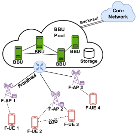
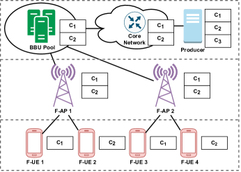
As a solution to this limitation, Fog Radio Access Network (F-RAN) was proposed as an evolution of C-RAN, which features an integration of fog computation with radio access networks [5]. In the context of an F-RAN, a Fog Access Point (F-AP) and Fog User Equipment (F-UE) provide functionality equivalent to the functionality of a base station and user equipment with additional features, such as edge caching and Artificial Intelligence [6], as we illustrate in Figure 1. F-RAN incorporates a number of cache-aided fog nodes in order to bring contents physically closer to users by offloading them to both F-APs and F-UEs. The main motivation behind the F-RAN architecture is to enable the BBU pool to serve more users by offloading popular contents to its F-APs and F-UEs. As a result, during the peak hours, the F-UEs can retrieve requested data from nearby F-APs or other F-UEs via Device-to-Device (D2D) communication when possible.
At the same time, NDN is the most mature information-centric networking architecture [7]. NDN is destined to replace the current IP-based Internet architecture with a data-centric communication model. In a traditional IP network, a user’s request contains the information of the desired host, and a connection is established between the host and the user for data exchange. Contrary to that, a user directly requests the desired data in NDN. In NDN, each piece of data is identified through a name and carries a cryptographic signature generated by the producer of the data. Each NDN router stores the information necessary to forward requests for data in its Forward Information Base (FIB). NDN routers also cache copies of requested data in their Content Store (CS). Requested data can be satisfied with data cached in CS, reducing the incurred latency and increasing efficiency. Finally, NDN routers aggregate requests for the same data in their Pending Interest Table (PIT), which prevents overloading the network with multiple requests for the same data.
I-B Related Work
F-RAN has attracted a lot of attention in recent years. Since the key feature of F-RAN is edge caching, most of prior works are focused on optimized content placement and delivery scheduling. Kavena et al. proposed an optimal energy-aware scheduling algorithm using network coding to offload popular contents from the BBU to F-UEs [8]. Shnaiwer et al. proposed a cache offloading scheme based on opportunistic network coding for macrocell base stations using femtocache in F-RAN [9]. The combination of F-RAN with heteregeneous wireless technologies, such as LTE and WiFi, was also explored to increase throughput [10]. Hu et al. reduced content response latency by adopting a caching design for enhanced remote radio heads based on a geographic distribution [11].
Several applications have shown improved performance with the help of NDN [12]. Lei et al. proposed a probability-based multipath forwarding using NDN for 5G [13]. Liao et al. , motivated by the upcoming surge in virtual and augmented reality, proposed a large-scale content distribution model for 6G using NDN [14]. The application of NDN in fog networks have been also investigated. Hua et al. presented a fog caching design scheme in NDN [15]. Liang et al. explored the possibility of combining NDN and wireless network virtualization [16]. The work by Zhang et al. presented a NDN-enabled 5G architecture based on the 3GPP standards [17].
Furthermore, approaches to optimize in-network data caching in NDN have been explored. ProbCache in [18] was introduced as a probability-based in-network caching algorithm. Zhang et al. in [17] employed an auction-based caching strategy to reduce data access delay and increase efficiency in content delivery. H2NDN in [19] was proposed with a frequency-based cache allocation scheme in order to move popular cached data closer and less popular data further from users. Finally, an optimal cache budget distribution for NDN networks was proposed by Montazeri and Makaroff [20].
I-C Our Motivation and Contributions
In this paper, our motivation is to study the interplay between NDN and F-RAN. This can be advantageous, as we further discuss below. A key feature of the F-RAN edge devices is that they can have individual storage capabilities to cache data. Since F-RAN reduces latency and fronthaul usage by bringing popular data closer to users, it is crucial to have strategies and algorithms to identify popular data and place it on edge devices. These are challenging tasks that we need to carry out in order to have a feasible system. Incorporating NDN into the F-RAN architecture allows us to take advantage of the existing cache resources available on edge devices to realize NDN in-network caching. At the same time, F-RAN will no longer need to perform data caching at the application layer–caching will be performed by NDN directly at the network layer.
To realize an NDN-enabled F-RAN architecture, in this paper, we augment the protocol stack of the F-UE and F-AP, so that they are able to understand the semantics of NDN packet. In addition, we propose a data caching strategy to improve cache usage. Our contributions are the following:
-
•
We propose an NDN-enabled F-RAN architecture through modified designs of the F-UE and F-AP protocol stack to incorporate NDN into F-RAN.
-
•
We present a cache distribution problem along with an optimization function to effectively utilize the available cache resources in the network. Additionally, we propose a cache replacement algorithm for the NDN-enabled F-RAN components to improve cache usage.
-
•
Through a simulation study, we compare our data caching strategy with baseline strategies in terms of resource utilization, cache hits, and fronthaul channel usage.
II Enabling NDN in F-RAN
Modifications are needed for the F-RAN architecture to support NDN. These modifications are discussed in this section.
II-A NDN Principles
There are two types of packets in NDN: Interest packets and Data packets. An Interest packet contains the name of the Data requested by a consumer (user), and a Data packet contains the requested content along with some meta information and a signature. In NDN, data names are hierarchical, which allow routers to forward packets to their next hop(s) accordingly. Each NDN router maintains three data structures for its operation: FIB, PIT, and CS.
When an Interest packet arrives at a router, the router first checks if the requested Data packet is available in CS. If it is available, the router satisfies the Interest with the data from its CS. Otherwise, the router checks if the requested Data packet has already been requested by another consumer. If an Interest for the requested data is already in PIT, the router aggregates the new Interest. Otherwise, the router forwards the Interest packet to its next hop based on the name-based routing information available in FIB and creates a new PIT entry (stateful forwarding plane) [21]. When the requested data is received by a router as a Data packet, it is cached in its CS for future requests, and all the aggregated Interests in PIT are satisfied with the Data packet.
II-B NDN-Enabled F-AP
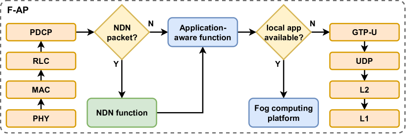
The original design of an F-AP for F-RAN has been proposed by Peng et al. [22]. The F-AP is based on a four layer protocol stack with additional functions for fog computation. 3GPP standards are preserved in the design. The physical (PHY), Medium Access Control (MAC), and Radio Link Control (RLC) layers are the same as C-RAN with the functionality of coding/modulation, mapping logical/transport channel, and segmentation/reassembly respectively. The Packet Data Convergence Protocol (PDCP) layer (responsible for IP header compression) sends packets to an application-aware function. The function extracts the IP address and port number of the requested application. A table of IP addresses and ports of the available fog applications is maintained, where the extracted IP and port number is matched. If the requested application is available, the function notifies the fog computing platform, initiating the requested application. The newly created application’s IP address and port number are forwarded to the user. If the application is not available, the packet is forwarded to the GPRS Tunneling Protocol (GTP-U) layer.
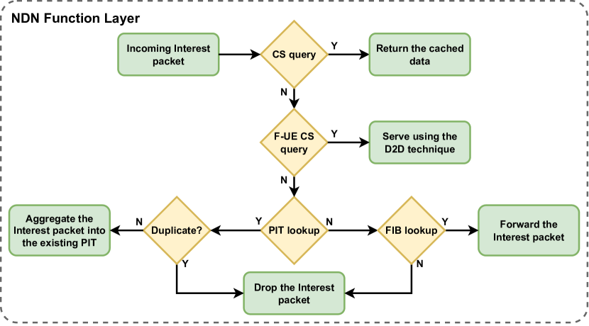
To enable NDN support for the F-AP design, an NDN function layer supporting the NDN protocol is proposed in Figure 2. The PHY, MAC, and RLC layers do not need modifications as these layer do not deal with the IP addresses. However, the PDCP layer needs to be updated to support both IP and NDN packets. When the PDCP layer forwards an NDN packet, it will be processed at the NDN function layer. The CS in the F-AP maintains the original cache and the information of the cache of its F-UEs. The function looks at the name of an Interest packet processed by the PDCP. If the requested data is available in the F-AP’s CS, it is returned right away. Otherwise, the function will check if one of the nearby F-UEs (within the consumer’s D2D communication region) has the requested data. If an F-UE has the data cached in its CS, D2D communication is established, allowing the F-UE to serve the data. The functionalities of PIT and FIB remain the same. The application-aware function needs to be updated as well to support NDN packets. The updated function will maintain an additional table with the names of the locally available applications. If an Interest packet’s name is found in the table, the fog computing platform will be notified. An NDN packet can be forwarded to the serving gateway using GTP-U and UDP/IP without modifications. Our proposed NDN-enabled F-AP design is able to handle both IP and NDN traffic.
II-C NDN-Enabled F-UE and BBU Pool
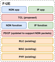
To enable NDN support for F-UEs, we present a dual stack protocol design (Figure 3). This protocol design ensures support for both NDN and IP. It will be up to the application to use either NDN or IP as the communication protocol. We propose an additional Transport Convergence Layer (TCL), which is responsible for sending NDN packets over an IP network if a radio access network does not support native NDN. The NDN packets can also be tunneled through IP over a network that does not have native NDN support using the NDN forwarding daemon [23].
The design of the BBU pool also requires changes to incorporate NDN. Our design of the BBU pool incorporates a core NDN component, which realizes the NDN protocol stack and is responsible for handling NDN traffic. Our design also incorporates a protocol conversion component, so that the BBU pool can communicate with the core network in cases that NDN is not supported by the core network. This is achieved by encapsulating NDN packets into IP packets.
III System Model
NDN allows F-RAN to store data directly at the network layer. The CS of each network node is automatically populated based on the data requested by users. In this section, we elaborate on the data caching problem and we present a cache replacement strategy to improve caching effectiveness.
III-A Data Caching Problem
In NDN, data caching strategies, such as Leave Copy Everywhere (LCE) for cache placement and First-In-First-Out (FIFO) for cache replacement, have been commonly used. Such strategies may not be suitable for F-RAN as every node in the network may cache the same data. To demonstrate the problem, a simple scenario is presented in Figure 4. In this scenario, there is a producer generating contents: , , and . A BBU from the BBU pool is serving F-AP 1 and F-AP 2. F-UE 1 and F-UE 2 are served by F-AP 1, and F-UE 3 and F-UE 4 are served by F-AP 2. Initially, every node’s CS is empty. In this scenario, both the BBU pool and F-APs can cache two contents, and each F-UE can cache one content in CS. The contents are requested in phases as described below.
First, F-UE 1 requests from the producer. F-AP 1 forwards the Interest packet to the serving BBU pool through the fronthaul channel and the BBU forwards the Interest packet to the core network via the backhaul channel, which eventually reaches the producer, and the requested Data packet is sent. Because of the LCE placement policy, the BBU, F-AP 1, and F-UE 1 will all store a copy of in their CS. Next, F-UE 2 requests . As a result, the CS in the BBU pool and F-AP 1 is now filled with and . Subsequently, F-UE 3 and F-UE 4 request and respectively. The BBU pool has both and available in its CS and it will serve both. However, F-AP 2 also has and in its CS. The BBU pool and the F-APs store the same content, which underutilizes the total available caching resources. Next, F-UE 1 and F-UE 2 request from the producer. Since every CS in the network is full, cache replacement is necessary to incorporate . If FIFO is used, will be replaced by in the BBU pool, F-AP 1, F-UE 1, and F-UE 2. Instead of replacing in the CS of both the BBU pool and F-AP 1, we could replace only F-AP 1’s cache with . This would have utilized cache resources more effectively, since if F-UE 1 or F-UE 2 were to request again, the BBU pool could serve it.
| Notation | Definition |
|---|---|
| Set of all Data packets. | |
| Set of all nodes (BBUs, F-APs, and F-UEs). | |
| Set of all F-UEs where | |
| Set of all F-APs and BBUs where . | |
| Set of all children of . | |
| Request rate of at . | |
| Binary decision variable for cache availability | |
| of at . | |
| Hop distance from the core network to . | |
| CS size of . |
III-B Proposed Caching Strategy
First of all, popular cached contents need to be identified, which can be done by analyzing the request rate of a content piece at a particular node. In other words, if the rate of requesting a specific Data packet is higher at a node, the node should hold on to that cached content for a longer period of time. For example, more popular contents based on the request rate will be served by the F-AP and less popular contents will be served from the BBU pool. Since the BBU pool will only receive the Interest packets not satisfied by F-APs, requests for less popular caches should aggregate there. Subsequently, the cache will be distributed among the nodes in the network based on the request rate of the Data packets at each node. To improve cache distribution efficiency, cached contents with a high request rate should be cached further away from the core network (i.e, closer to users). This can be achieved by optimizing the following objective function (notations are defined in Table I):
| (1) | ||||
| s.t. | (2) |
This indicates that caching data with greater request rates () further away from the core network based on number of hops () should be maximized within the limit of at each node (). At an F-UE, the request rate of a data piece is defined as the number of Data packets not satisfied by the consumer F-UE; whereas the request rates at the F-APs and BBU pool are the total number of unsatisfied Interest packets coming from its children within a given period of time. The request rate for each Data packet is calculated using the following equation:
| (3) |
where is a binary decision variable, which indicates the availability of data at node . As such, it can be defined as follows:
| (4) |
The problem in (1) is NP-hard as it can be reduced to a zero-one linear programming problem. The proof is presented in Appendix A.
III-C Data Caching Algorithm
The request rate for each Data packet is calculated using (3). However, the request rate is subject to change at any time; thus, a node should update the request rates after seconds. To make the changes in a more granular rate, a weighted average approach is taken into account based on the following equation:
| (5) |
where is the weight of the newly calculated request rate after seconds, and is the weight of the existing request rate. Algorithm 1 presents the cache distribution algorithm, which runs on each individual node in F-RAN. The algorithm is based on the principals of NDN along with our proposed caching strategy. When a node receives Interest packets from a child node (line 4), it checks , and to forward the Interest packet according to the NDN protocol. When the algorithm receives the corresponding Data packet, it satisfies the pending requests (line 11). To cache the Data packet, it first checks if there is any space available in (line 14). Otherwise, it finds the Data packet with minimal and hops and compares it with the received Data packet (line 17). If the existing Data packet has lower and hops, it is replaced by the new Data packet (line 21). After seconds the algorithm updates the request rates () of each Data packet using (5) (line 24). The complexity of the algorithm is , where is the size of the and is the size of .
IV Simulation Results and Discussion
We conduct a simulation study to evaluate the the proposed caching strategy, which we compare with two baseline caching algorithms, FIFO and Least Recently Used (LRU). Our simulation topology contained a central BBU pool, five F-APs, and a range of F-UEs (ranging from five to thirty). The central BBU pool served five F-APs, and each F-AP served one to six F-UEs. Each F-UE generated Interest packets following a Zipf distribution. Simulations were done with D2D communication enabled and disabled, assuming that each F-UE under an F-AP was within the range of D2D communication.
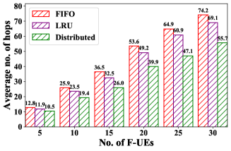
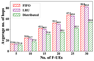
Average number of hops: Figures 5a and 5b present the average number of hops used by F-UEs without and with using D2D communication respectively. As the number of F-UEs increases, the number of requests and the required hops increase as well. Fewer hops indicate that an Interest was satisfied by a nearby node with lower latency. With the increasing number of users, the proposed caching strategy was able to utilize more cache resources in the network for data distribution, decreasing the overall latency with and without D2D communication.
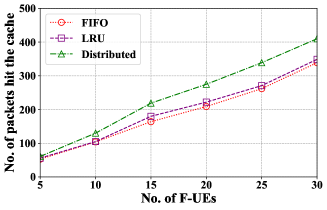
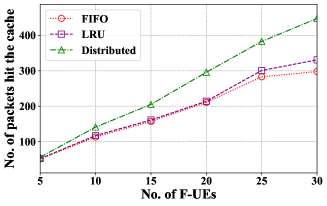
Cache hits: Figures 5c and 5d present the number of Interests packets that were served by in-network caches without and with D2D communication respectively. As the number of F-UEs increases, the proposed caching strategy served more packets from in-network caches compared to other strategies. Furthermore, the proposed caching strategy benefits from increasing the number of F-UEs in both cases (with and without D2D communication).
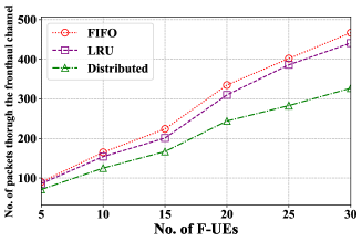
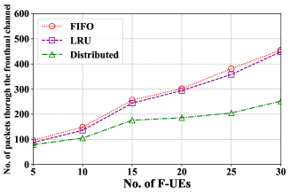
Fronthaul channel usage: We measured the number of packets that used the fronthaul channel to reach the central BBU pool. As shown in Figures 5e and 5f, the fronthaul channel usage decreased the most when D2D was enabled. As the number of F-UEs increases, more cache resources become available and the fronthaul usage decreases.
V Conclusion
In this paper, we presented a design to incorporate NDN into the F-RAN architecture. Our main motivation was to reduce the burden on the fronthaul channel by allowing edge nodes to cache popular data. We proposed a caching strategy to achieve that and presented NDN-enabled designs for F-APs and F-UEs. Our simulation study showed that the proposed caching strategy can reduce the usage of the fronthaul channel, reduce the number of hops required for data retrieval, and increase cache hits as compared to baseline caching strategies.
Appendix A Proof of NP-Hardness of the Caching Problem
To prove that the problem in (1) is NP-hard, an F-RAN topology is considered that includes a central BBU pool , two F-APs (), and two F-UEs (). and are served by and respectively. Interest packets for content and are generated by and respectively.
Request rates at and are:
| (A.1) |
Request rates at are:
| (A.2) | |||
| (A.3) |
We need to optimize the following:
| (A.4) | ||||
| s. t. | ||||
| (A.5) |
By rearranging (A), we have:
| (A.6) |
where is a binary decision variable, which means some multiplications can be be replaced with the following variables given they satisfy the constrains:
| (A.7) |
| (A.8) |
With the replacement of variables from (A.7) and (A.8), (A.6) can be rewritten as a zero-one linear programming problem, which is NP-hard:
| (A.9) |
Acknowledgements
This work is partially supported by the National Science Foundation through awards CNS-2104700, CNS-2016714, and CBET-2124918, as well as the National Institutes of Health through award NIGMS/P20GM109090.
References
- [1] Amin Shahraki et al. A Comprehensive Survey on 6G Networks: Applications, Core Services, Enabling Technologies, and Future Challenges. arXiv preprint arXiv:2101.12475, Jan. 2021.
- [2] M. Peng, Y. Li, Z. Zhao, and C. Wang. System architecture and key technologies for 5G heterogeneous cloud radio access networks. IEEE Network, 29(2):6–14, Mar. 2015.
- [3] M. Peng et al. Recent advances in cloud radio access networks: system architectures, key techniques, and open issues. IEEE Communications Surveys Tutorials, 18(3):2282–2308, Mar. 2016.
- [4] M. Labana and W. Hamouda. Advances in CRAN performance optimization. IEEE Network, pages 1–7, Sep. 2020.
- [5] H. Zhang et al. Fog radio access networks: mobility management, interference mitigation, and resource optimization. IEEE Wireless Communications, 24(6):120–127, Dec. 2017.
- [6] Mugen Peng, Zhongyuan Zhao, and Yaohua Sun. System Architecture of Fog Radio Access Networks, pages 21–40. Springer International Publishing, Cham, 2020.
- [7] Lixia Zhang et al. Named data networking. ACM SIGCOMM Computer Communication Review, 44(3):66–73, 2014.
- [8] K. Kaneva, N. Aboutorab, S. Sorour, and M. C. Reed. Energy-aware cross-layer offloading in fog-RANs using network coded device cooperation. IEEE Access, 8:169930–169943, 2020.
- [9] Y. N. Shnaiwer et al. Network-coded macrocell offloading in femtocaching-assisted cellular networks. IEEE Transactions on Vehicular Technology, 67(3):2644–2659, Mar. 2018.
- [10] Y. N. Shnaiwer, S. Sorour, T. Y. Al-Naffouri, and S. N. Al-Ghadhban. Opportunistic network coding-assisted cloud offloading in heterogeneous fog radio access networks. IEEE Access, 7:56147–56162, Apr. 2019.
- [11] J. Hu et al. Simultaneous wireless content and power transfer in F-RAN: caching, eRRH classification and beamforming. IEEE Transactions on Vehicular Technology, 69(11):12992–13004, Nov. 2020.
- [12] G. Mauri, M. Gerla, F. Bruno, M. Cesana, and G. Verticale. Optimal content prefetching in NDN vehicle-to-infrastructure scenario. IEEE Transactions on Vehicular Technology, 66(3):2513–2525, Mar. 2017.
- [13] K. Lei et al. An NDN IoT content distribution model with network coding enhanced forwarding strategy for 5G. IEEE Transactions on Industrial Informatics, 14(6):2725–2735, Jun. 2018.
- [14] S. Liao, J. Wu, J. Li, and K. Konstantin. Information-centric massive IoT based ubiquitous connected VR/AR in 6G: a proposed caching consensus approach. IEEE Internet of Things Journal, Oct. 2020.
- [15] Yining Hua, Lin Guan, and Konstantinos G. Kyriakopoulos. A fog caching scheme enabled by ICN for IoT environments. Future Generation Computer Systems, 111:82–95, Oct. 2020.
- [16] C. Liang, F. R. Yu, and X. Zhang. Information-centric network function virtualization over 5G mobile wireless networks. IEEE Network, 29(3):68–74, May 2015.
- [17] T. Zhang, X. Fang, Y. Liu, and A. Nallanathan. Content-centric mobile edge caching. IEEE Access, 8:11722–11731, Dec. 2020.
- [18] Ioannis Psaras, Wei Koong Chai, and George Pavlou. Probabilistic in-Network caching for information-centric networks. In Proc. of the Second Edition of the ICN Workshop on Information-Centric Networking, ICN ’12, page 55–60. Association for Computing Machinery, 2012.
- [19] N. Yang, K. Chen, and Y. Liu. Towards efficient NDN framework for connected vehicle applications. IEEE Access, 8:60850–60866, 2020.
- [20] A. Montazeri and D. Makaroff. Optimal cache budget distribution for hierarchical ICN networks. In Proc. of the 22nd Conference on Innovation in Clouds, Internet and Networks and Workshops (ICIN), pages 336–343, Paris, France, Feb. 2019.
- [21] Md Washik Al Azad and Spyridon Mastorakis. Reservoir: Named data for pervasive computation reuse at the network edge. In 2022 IEEE International Conference on Pervasive Computing and Communications (PerCom), pages 141–151. IEEE, 2022.
- [22] Mugen Peng, Zhongyuan Zhao, and Yaohua Sun. Prototype Design of Fog Radio Access Networks, pages 179–201. Springer International Publishing, Cham, 2020.
- [23] Alexander Afanasyev, Junxiao Shi, et al. NFD developer’s Guide. Technical Report NDN-0021, NDN, 2015.