001 11institutetext: Helmholtz-Zentrum Dresden-Rossendorf, Institute of Fluid Dynamics, Bautzner Landstrasse 400, D-01328 Dresden, Germany 22institutetext: Department of Aerodynamics and Fluid Mechanics, Brandenburg University of Technology, Cottbus-Senftenberg, 03046 Cottbus, Germany 33institutetext: Institute of Geophysics of the Czech Academy of Sciences, Boční II/1401, 141 31 Praha 4 – Spořilov, Czech Republic
Numerical and theoretical framework for the DRESDYN precession dynamo experiment
Abstract
The upcoming DRESDYN (DREsden Sodium facility for DYNnamo and thermohydraulic studies) precession experiment will test the possibility to achieve magnetohydrodynamic dynamo action solely driven by precession. Here, after the description of the experimental facility, we present the results from direct numerical simulations with the aim to understand the flow behavior and its dynamo capability. The main conclusion is that in the nonlinear regime the nutation angle is an essential governing parameter which determines the flow structures and the possibility of dynamo action. We obtain clear indications about the optimum configuration for the future experimental runs.
Introduction.
Precession is believed to be a complementary energy source for
the geodynamo [1] or the ancient lunar dynamo [2].
Several laboratory experiments [3, 4, 5]
and numerical simulations [6, 7, 8, 9]
have challenged the corresponding flow problem in cylindrical geometry (which
shows commonalities with spheroidal topology) in order to understand the
basic hydrodynamic mechanisms. One of the main motivations in selecting
cylindrical geometry to achieve a precession driven dynamo was the experimental
work by Gans [10] who had observed an amplification of an imposed
magnetic field by factor 3.
The DRESDYN precession experiment at HZDR (Helmholtz-Zentrum Dresden-Rossendorf)
consists of a cylinder with radius 1 m and height 2 m which will rotate at up
to 10 Hz and precess at up to 1 Hz (Fig. 1) [11, 12].
The experimental studies so far were performed in a down-scaled cylinidrical
container (R=H/2=0.163 m) filled with water in order to provide detailed
measurements of the flow structure [5]. At the same time
non-linear hydrodynamic simulations were carried out and compared with
the experimental results [8]. In this paper we present
results from DNS (direct numerical simulations) performed at several
precession angles in order to find the dynamical characteristics to be
expected in the future experiments. These hydrodynamic simulations provide
the flow structures which are used as input for kinematic dynamo simulations
with the goal to assess in which parameter ranges the occurrence of dynamo
action is most likely.
1 The DRESDYN precession experiment.
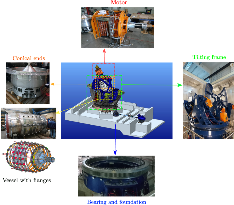
As shown in Fig. 1 the precession dynamo experiment is a large and complex machine which operates at the edge of technical feasibility. The “core” of this facility is represented by a cylindrical stainless-steel vessel whose aspect ratio () is the most efficient one to drive an intense flow. On the sidewall 40 flanges are mounted which will contain the probes to measure the flow field pressure in the preliminary water experiments. They will be complemented by Hall sensors in the later sodium experiment. The vessel is fixed in a traverse and pylons which jointly represent the tilting frame which makes it possible to vary the nutation angle of the cylinder. During the dynamo experiments, the container contains 8 tons of liquid sodium. Because of the high flammability of the working fluid a fire extinguishing system with liquid argon has been installed. The mechanical power required to rotate the cylinder is provided by an electric motor of 900 kW while for the rotating turntable it is 540 kW. Due to the extremely high gyroscopic torque (up to 8 MNm) the basement has been built with ferro-concrete material and the foundation sits on 7 pillars with a depth of 22 m. The machine will allow to achieve a Reynolds number of and a magnetic Reynolds number of making it possible to investigate hydrodynamic and magnetohydrodynamic ranges so far not reached.
2 Mathematical formulations and numerical methods.
2.1 Hydrodynamic model.
We consider an incompressible fluid enclosed in a cylindrical container which is subject to precession. The main geometrical parameter is the aspect ratio , i.e. the ratio of height over radius, which is fixed to 2. The nutation angle , whose influence is the main focus in this paper, is measured from the precession to the rotation axes (Fig. 1). The governing equations read [13]
| (1) |
with being the flow velocity, P the reduced pressure, the rotation angular velocity and the precession angular velocity. The other governing parameters are the Reynolds and Poincaré numbers:
| (2) |
where the in front of the precession ratio means prograde (the projection of the turntable rotation on the cylinder rotation is positive) or retrograde motion (projection is negative). In order to postprocess the results from simulations we decompose the fluid flow into its inertial mode components [7]
where means complex conjugate, is the boundary layer velocity and is the position vector. The triplet represents the azimuthal, axial and radial wave numbers. The amplitude of each inertial mode is computed projecting the simulated velocity on which are the eigenfunctions of the linearized inviscid form of Eq. 1 [14].
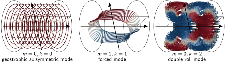
Figure 2 represents the 3D structures of the most prominent inertial modes occurring in a fluid filled precessing cylinder: the central one is the directly forced mode caused by the gyroscopic effect on the fluid flow which dominates in the laminar regime, i.e for weak forcing. Once the precession ratio increases, the other two modes emerge due to the nonlinear phenomena enriching the dynamics of the flow. In particular the (0,0) mode resembles a columnar vortex which counteracts the solid body rotation while the (0,2) is a poloidal flow analogous to the Taylor vortices found in other fluid dynamics problem [8, 13].
2.2 MHD model: Induction equation.
We run purely hydrodynamic simulations until the flow field achieves a statistically stable regime. Then, we insert the time-averaged velocity into the induction equation
| (3) |
The second condition expressed in Eq. (3) represents the solenoidal nature of the magnetic field. For the time-averaged velocity field considered constant, the solution of the linear evolution equation has the form with representing the eigenvalue. In Eq. (3) is the magnetic Reynolds number, defined as , where is the magnetic diffusivity of the liquid metal. While for the hydrodynamic problem we use a spectral element-Fourier code [15] with no slip boundary condition, we solve the induction equation through a finite volume scheme with constraint transport in order to ensure the divergence-free nature of the magnetic field. As boundary conditions we use the so-called pseudo vacuum condition i.e, only the tangential components of the magnetic fields vanish at the wall. Even if this model lack of physical consistency it is a good approximation since it is computationally faster and the results are not far from those using correct boundary conditions [16]. We present results at fixed for which we study the role of the nutation angle which will be shown to be substantial both for hydrodynamic and magnetohydrodynamic behavior.
3 Hydrodynamic Results.
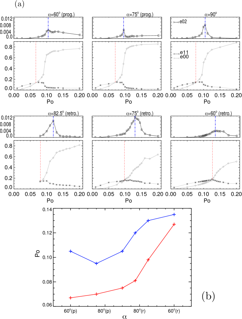
The most dominant modes emerging in a precessing cylinder, schematically shown in Fig. 2, are quantified in terms of their kinetic energies (normalized with the energy of solid body rotation) in Fig. 3(a). For each angle we plot the axisymmetric-geostrophic energy , the directly forced flow energy and (in a separated panel due to the difference in order of magnitude) the axisymmetric poloidal energy . The prograde and cases (top row) show a clear transition between a weak forcing region dominated by and a strong forcing region where accounts for of the total energy. For the retrograde cases, only the (for which we do not have simulation for ) case undergoes a marked breakdown of with a “jump” of while the smaller show a smoother profiles of the when increases. The red curves mark the crossing of the two energy profiles which occur at different as plotted as a red solid line in 2(b). With these points coincides a shift from the directly forced dominated to a geostrophic dominated flow which has an impact also on the boundary layers [17]. The last contribution shown is . Also for this component the nutation angle plays a crucial role in terms of magnitude, shape of the profiles and the location of the peaks (dotted blue curve). Indeed we plot the position of max() as a function of precession ratio in Fig. 3(b) observing a shift towards larger for the retrograde cases.
4 Dynamo action
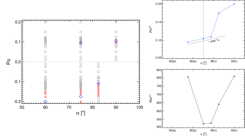
Having observed that the nutation angle (and of course the
precession ratio Po) influences substantially the flow field, we
check now the role of for the precession driven flow
to act as dynamo, i.e. to have a positive growth rate of the
magnetic energy. The first general result is the phase
diagram (Po, ) shown in Fig. 4
where the red symbols show the dynamo cases, while the black
symbols stands for no-dynamo. We observe that the retrograde
motion (negative semiplane) is more prone to dynamo action while
the prograde cases show only few red points. Interestingly
the case is not able to drive a dynamo at
all. By contrast, notice the more extended region of red symbols
at retrograde. The blue diamonds mark the
strongest dynamo for each angle and they are plotted in the
top-right figure as optimum precession ratio function
of . Notably the profile presents an asymmetry with
respect to since the linear trend includes also the
retrograde case and the jump does not
coincide with . In the right bottom plot
is shown the critical magnetic Reynolds number (i.e. the
lowest for the occurrence of dynamo action) versus the
nutation angle. Evidently, the role of is crucial
in order to reduce as much as possible the threshold for
the onset of dynamo, and it is clear that the optimum range
is retrograde.
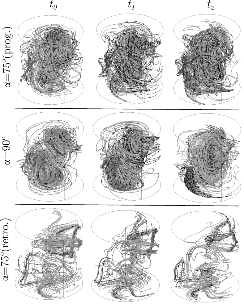
As a final result we show in Fig. 5 the three dimensional magnetic field lines developed inside the container at three different times (columns) for three different nutation angles. The main outcome is that causes a substantial difference in the geometry and the time-evolution of the field. The retrograde case presents less dense field lines with quite chaotic shape, while the shows the most coherent topology characterized by two clear vortices with opposite rotations (visible as black arrows) which change over time: e.g. at the bottom large vortex is clockwise while at it becomes counterclockwise.
5 Conclusions and outlook
The nutation angle is a crucial governing parameter for precession driven flows in cylindrical geometry whose role is far from trivial, especially in the nonlinear regime. It determines the flow topology and the magnitude of particular structures both for the flow and the dynamo generated magnetic field. As a consequence the possibility to achieve dynamo action is strongly influenced by the angle. The results of this paper give general indications about the best region in the phase space for the dynamo action: the optimum angle was found to be around retrograde. Future studies will focus on the extension of the analysis on other Reynolds number and to the impact of realistic magnetic boundary conditions.
This project has received funding from the European Research Council (ERC) under the European Union’s Horizon 2020 research and innovation program (Grant Agreement No. 787544), and from Deutsche Forschungsgemeinschaft under Project No. GI 1405/1-1.
References
- [1] W. V. R. Malkus. Precession of the Earth as the cause of geomagnetism. Science, Vol. 160 (1968), pp. 259–264.
- [2] C. A. Dwyer, D. J. Stevenson, and F. Nimmo. A long-lived lunar dynamo driven by continuous mechanical stirring. Nature, Vol. 479 (2011), pp. 212–214.
- [3] R. Manasseh. Breakdown regimes of inertia waves in a precessing cylinder. J. Fluid Mech., Vol. 243 (1992), pp. 261–296.
- [4] P. Meunier, C. Eloy, R. Lagrange, and F. Nadal. A rotating fluid cylinder subject to weak precession. J. Fluid Mech., Vol. 599 (2008), pp. 405–440.
- [5] J. Herault, T. Gundrum, A. Giesecke, and F. Stefani. Subcritical transition to turbulence of a precessing flow in a cylindrical vessel. Phys. Fluids, Vol. 27 (2015), Art. No. 124102.
- [6] C. Nore, J. Léorat, J. L. Guermond, and F. Luddens. Nonlinear dynamo action in a precessing cylindrical container. Phys. Rev. E, Vol. 84 (2015), Art. No. 016317.
- [7] D. Kong, Z. Cui, X. Liao, and K. Zhang. On the transition from the laminar to disordered flow in a precessing spherical-like cylinder. Geophys. Astrophys. Fluid Dyn., Vol. 109 (2015), pp. 62–83.
- [8] A. Giesecke, T. Vogt, T. Gundrum, and F. Stefani. Nonlinear large scale flow in a precessing cylinder and its ability to drive dynamo action. New. J. Phys., Vol. 120 (2018), Art. No. 024502.
- [9] A. Giesecke, T. Vogt, T. Gundrum, and F. Stefani. Kinematic dynamo action of a precession-driven flow based on the results of water experiments and hydrodynamic simulations. Geophys. Astrophys. Fluid Dyn., Vol. 113 (2019), pp. 235–255.
- [10] R. F. Gans. On hydromagnetic precession in a cylinder. J. Fluid Mech., Vol. 45 (1971), pp. 111–130.
- [11] F. Stefani, S. Eckert, G. Gerbeth, A. Giesecke, T. Gundrum, C. Steglich, T. Weier, and B. Wustmann. DRESDYN – a new facility for MHD experiments with liquid sodium. Magnetohydrodynamics, Vol. 48 (2012), pp. 103–114.
- [12] F. Stefani, T. Albrecht, G. Gerbeth, A. Giesecke, T. Gundrum, J. Herault, C. Nore, and C. Steglich. Towards a precession driven dynamo experiment. Magnetohydrodynamics, Vol. 51 (2015), pp. 275–284.
- [13] F. Pizzi, A. Giesecke, J. Šimkanin, and F. Stefani. Prograde and retrograde precession of a fluid-filled cylinder New. J. Phys., Vol. 23 (2021), Art. No. 123016.
- [14] H. P. Greenspan. The Theory of Rotating Fluids. (Cambridge University Press, U.K, 1968).
- [15] H. M. Blackburn, D. Lee, T. Albrecht, and J. Singh. Semtex: a spectral element-Fourier solver for the incompressible Navier-Stokes equations in cylindrical or Cartesian coordinates. Comput. Phys. Comm., Vol. 245 (2019), Art. No. 106804-1-13.
- [16] A. Giesecke, F. Stefani, and J. Burguete. Impact of time-dependent nonaxisymmetric velocity perturbations on dynamo action of von-Kármán-like flows. Phys. Rev. E, Vol. 86 (2012), No. 6, Art. No. 066303.
- [17] F. Pizzi, A. Giesecke, and F. Stefani. Ekman boundary layers in a fluid filled precessing cylinder. AIP Advances, Vol. 11 (2021), Art. No. 035023.