How heterogeneous wettability enhances boiling
Abstract.
For super-heated water on a substrate with hydrophobic patches immersed in a hydrophilic matrix, one can choose the temperature so that micro-bubbles will form, grow and merge on the hydrophobic patches and not on the hydrophilic matrix. Until covering a patch, making a pinned macro-bubble, a bubble has a contact angle , where is the receding contact angle of water on the patch material. This pinned macro-bubble serves as the initial condition of a quasi-static growth process, à la Landau, leading to detachment through the formation of a neck, so long as depinning and dewetting of the hydrophilic matrix was avoided during the growth of the pinned bubble: the bubble contact angle should not exceed , where is the receding contact angle of water on the matrix material. The boiling process may then enter a cycle of macro-bubbles forming and detaching on the patches; the radii of these patches can be optimized for maximizing the heat transfer for a given substrate area.
For this analysis to become quantitative, we revisit the Young-Laplace quasi-static evolution of key physical quantities, such as bubble energy, as functions of bubble growing volume, when gravity is either significative or negligible: this concerns both pinned bubbles on a fixed circular footprint (Dirichlet boundary conditions) and free un-pinned bubbles with a fixed contact angle (Neumann boundary conditions).
Keywords: Young-Laplace; quasi-static; heterogeneous wettability; boiling.
1. Introduction
Boiling is a common heat transfer technique. It occurs when a liquid is exposed to a surface which is maintained above saturation temperature. This surface can be homogeneous or heterogeneous. The wall temperature () of the liquid needs to be higher than the saturation temperature of the liquid (). If the wall temperature is sufficiently high, a thin layer of vapour is formed. This condition, characterized by a vapour film formation on the heated surface, is called film boiling. The extensive study on the effect of the very large superheat difference () between temperature of the heating surface () and the saturated liquid (), was first done by Nukiyama, [9]. However, it was the experiment by Farber and Scorah, [4], that gave the complete picture of the heat transfer rate in the pool boiling process (boiling without flow) as a function of . See also [14] and references therein. The various regimes of boiling in a typical case of pool boiling in water at atmospheric pressure are shown in Fig. 1. It is the conventional representation of heat flux versus wall superheat. Different ranges can be identified while is increased.

This work focuses on pool boiling phenomena, looking in detail at the evolution of a single bubble. When the wall temperature reaches the condition =, a vapour bubble nucleates on the heater surface. The effect of the wettability on has been studied in Bourdon et al, [2] . This paper shows that a thin hydrophobic coating on a surface will significantly lower the onset of boiling. However, at the same time, it will promote the formation of a vapour layer which will in turn affect the critical heat flux.
To avoid this problem, heterogeneous surfaces have been proposed, [14]. These surfaces are generally hydrophilic with hydrophobic patches to decrease the onset of boiling and at the same time increase the critical heat flux.
The natural question is about the size of these patches. Is there an optimal size to promote boiling? To decrease ? This question refers of course to the basic mechanism controlling boiling on top of the surface.
Most probably, nanodroplets of vapour will form everywhere and will coalesce preferentially on top of the hydrophobic patches. This coalescence will occur until the contact area of the patch is covered by vapour and then the vapour bubble will grow until a certain volume where it will detach.
Herewith we consider the case where boiling includes a stage of slow bubble growth, well approximated by equilibrium shapes. Other cases with ultrafast heat transfer regimes exist but are not considered here; see [13].
It has been observed that both hydrophobic substrates and hydrophilic substrates have advantages with respect to boiling, see [11] and [15]. When the water contact angle tends to 180∘ (Fig. 2, left), the configuration approaches a configuration without bubble and the nucleation barrier disappears as is clear from Young’s equation. This is favorable in the first step of the boiling process. However, as we shall see, the almost flat bubble will need to grow to a very large volume before developing a neck and detaching. This is unfavorable. On the other hand, when tends to zero (Fig. 2, right), the configuration tends to that of a free bubble, homogeneous nucleation with a high barrier. The presence of a neck from the beginning, a favorable factor, is not enough to win the game. A natural answer is to try a patterned surface allowing nucleation on hydrophobic patches, surrounded by a hydrophilic matrix confining the base of the bubbles and forcing formation of neck. Whether it works, and with what size of patch and detaching bubbles, is the main motivation in the present study.

The organization of the paper is as follows:
In Section 2.1, using Young-Laplace equations for axisymmetric bubbles, we compute the quasi-equilibrium evolution à la Landau of various physical quantities of interest as a function of its growing volume, first for pinned bubbles on a fixed circular footprint (Dirichlet boundary conditions). It includes the mechanical (potential) energy , the contact angle , the height , the pressure and the curvature radius at the apex. The quasi-equilibrium regime stops when the energy attains its maximal value where the bubble enters a non-equilibrium regime leading to its detachment after the formation of a neck.
For completeness, in Section 2.2, we do the same for free (un-pinned) bubbles having a fixed contact angle (Neumann boundary conditions). Of particular interest in this setup is the quasi-equilibrium evolution of the radius of the bubble footprint till its detachment. We show that this radius can grow and then shrink in the process.
In the latter two studies, gravity is present and competes with surface effects.
In Section 2.3, we show how these computations simplify in the absence of gravity (or when gravity is negligible), leading to spherical cap profiles. The Young-Laplace equations are explicitly integrable with the evolution of as functions of volume, following directly from the one of
We then address the question of the onset of boiling of water on a hot substrate, through vapour micro-bubble nucleation, so when gravity can be neglected and when the driving force of bubble growth is a temperature gradient. We show that, in order for micro-bubbles to form and grow, the applied must exceed some that can be estimated as a function of the substrate wettability. This is shown to be a decreasing function of the liquid contact angle at the base of the bubble and so hydrophobicity favors boiling. If the substrate is thus made of hydrophobic patches immersed in a hydrophilic sea (patterning), for each choice of their wettabilities, there is a choice of for which micro-bubbles form and grow on the hydrophobic patches and not on the hydrophilic sea. Once these micro-bubbles have formed on the hydrophobic part of the substrate, each grows, showing up a hydrophobic liquid contact angle, possibly merge till covering the patch where the macro-bubble thus formed becomes pinned. At this point, the contact angle of the liquid at the base of the bubble is the hydrophobic receding liquid contact angle. This macro-bubble serves as the initial condition of its quasi-equilibrium evolution described in Section 2.1 till detachment.
In Section 3, we address the question of the temporal evolution of the quasi-static bubble growth regime. Using an Onsager ansatz for the evolution of the number of vapour moles and assuming vapour can be treated as a perfect gas, we show that during its growth stage, the bubble volume grows ‘nearly’ linearly with time both in the presence of gravity and when gravity is negligible.
Section 4 is devoted to a discussion of the ‘optimal’ patch radius as a function of the contact angle of the liquid on the patch (hydrophobic) and the liquid contact angle on the matrix (hydrophilic). By optimal, we mean the radius for which heat transfer is maximal, for a given substrate area and for given materials specifying the contact angles on the patch and the matrix.
2. Computation of the bubble profiles
In [8] the authors analyze the equilibrium bubble profiles when air is blown quasi-statically through a nozzle. When dealing with boiling of water on a patterned substrate, the driving process for bubble formation is now heat transfer at the circular patch boundary, generating quasi-statically water vapor. The successive bubble profiles, under the quasi-static approximation, clearly are the same. Pool boiling based on principles of equilibrium thermodynamics was shown relevant in [1].
The coordinate system is outlined in Fig. 3a with the origin located at the apex, is the axis of symmetry and with the -axis radially outwards.

At a point at abscissa from , the pressure in the liquid is given by
| (1) |
where is the pressure at in the liquid, is the liquid density and the gravity constant. The vapour pressure in the bubble is given by the Laplace equation:
| (2) |
where is the mean curvature , and and are the principal radii of curvature with signs, at a point of the liquid/vapour interface and the liquid/vapour surface tension. The vapour pressure is assumed uniform inside the bubble due to the comparatively small value of the vapour density. Therefore, with the water density,
| (3) |
At , where is the radius of curvature at the apex . Therefore and so
| (4) |
For axi-symmetric shapes, the radii of curvature and can be expressed as
| (5) |
where is the profile arc-length from the origin located at the apex to a given point of the profile and the angle between the tangent of the profile at and the horizontal (recall is the contact angle seen from the liquid). Then
| (6) |
We obtain the final system of ordinary differential equations (LH for short) with three dependent variables , see [8],
| (7) |
with initial conditions This system can be integrated numerically to generate the bubble profile for various values of the control parameter . In the boiling experiment of water, we take kg/m and N/m at ∘K.
We can create the profiles computed as functions of for different values of the inverse curvature at the apex. The profiles are Delaunay curves. The profile curves are then available as well, [8]. The family of profile solutions to the (say LH for Longuet-Higgins) Eqs. 2 is shown in Fig. 3b.
The latter system could be adimensionalized by introducing the capillary length as the length-scale mm.
2.1. Pinned bubble on a patch with prescribed radius at the bottom (Dirichlet boundary condition)
To obtain the solutions for a given contact patch with radius , we intersect the profiles computed in the previous figure with the lines . For example, for a radius of curvature mm, there are three curves that satisfy mm as is shown in Fig. 4.

The system yields the corresponding full bubble profile pinned on the patch, in particular the value of the height of the bubble with patch radius .
For each intermediate equilibrium profile with fixed patch radius , the bubble has a vapour contact angle at the plate and, with the volume of the corresponding intermediate bubble, by Archimedes principle,
| (8) | |||||
| (9) |
translating the vertical balance of surface versus gravitational forces, in the spirit of Furmidge, [5]. We have checked this equation numerically, see Fig. 5.
See [5], Eq. (12), where was changed to while considering bubbles instead of drops.
This is in particular true when and , where reaches the terminal value .
We give the profiles with mm for mm with a step mm. Subsequently, we can compute numerically the volume of the bubble, namely
| (10) |
where is the height of the bubble.
In Fig. 6a, we represent versus for mm. While following starting from large values, the volume of the bubble is seen to increase before it reaches a maximum volume at just after the appearance of a first neck in its profile which appears at when the tangent at the basis of the bubble becomes vertical for the second time after ; see Fig. 6b. So a neck appears if the bubble profile shows two vertical tangents or if there is a local minimum of other than 0 and .
For mm, there are configurations for which the neck does not appear in the equilibrium regime.

We get a sequence of bubbles for increasing volume from till that can be considered as a succession of equilibrium states and we are restricted to the curve shown in Fig. 6b.
Some of the profiles obtained are shown in Fig. 6c (the extreme right one corresponds to point with the maximum volume).
Fig. 7 shows the evolution of the mean curvature along the profile corresponding to such a ’terminal’ equilibrium profile before detachment. It decreases while descending from the apex to the bottom of the bubble but remains positive.

Consider a bubble of an increasing volume with the contact line pinned on a patch with radius mm. Beyond a volume , no solution either stable or unstable of LH equations, [8], were found numerically. After reaching , we expect to enter a non-equilibrium regime, leading eventually to the detachment of the bubble.
The height of the bubble at this volume is . From the LH expressions, [8], we are able to compute the equilibrium profiles and then, the surface areas, contact angle, energy and pressure.
Contact angle at the plate: The contact angle at the plate is computed from the tangent to the profile in contact with the plate. We let
Energy, [12]: The different contributions to the total energy are
- Gravitational and liquid/vapour interfacial energy:
| (11) |
| (12) |
- Surface energy at the Solid/Vapour and Solid/Liquid interfaces. With (by Young-Dupré equation where is the equilibrium Young angle of water),
| (13) |
The total mechanical energy (surface tension plus gravitational) then reads, dropping the constant
| (14) |
Due to the contact line pinning, does not change during the evolution of the bubble.
The total mechanical energy versus volume V is shown in Fig. 8 where we observe that increases until a maximal value . After having reached , the energy decreases together with . The point is a singular point and the bubble will evolve towards detachment when V increases beyond
We have the following formula under the Dirichlet b.c.
| (15) |
For Neumann b.c., we expect .

Fig. 8, a plot of against shows that increases until a maximal volume is reached. After having reached , the energy decreases together with . The point is a singular point and the bubble will evolve towards detachment when .
Pressure: The pressure in the bubble is computed as
| (16) |
where is the liquid pressure at the plate, taken as where is the height of water above the plate assuming and Pa is the atmospheric pressure.
If we are to apply this theory to a pinned bubble growing on a hydrophobic patch (Young angle ) immersed in a hydrophilic matrix (Young angle ), we need to impose the condition for all angles appearing in the formation history of the bubble, in particular the terminal one (when ) but not only. This is possible and the worst case where this condition could be violated is after point (where the tangent to the bubble is vertical for the first time). If this condition is not met, the bubble overflows the patch before reaching its terminal state for detachment.
The condition for all angles appearing in the formation history of the bubble is also required for pinning. If this condition is not met, the bubble would de-pin before reaching its terminal state for detachment.
It seems to suggest that growing a bubble in this way on a hydrophobic patch is impossible because then at least at the early stages of the bubble growth with small and so large , unless ideally . In fact (under the conditions below), only on the hydrophobic patch do micro-bubbles grow, invade the patch with radius and then the initial condition for LH should be started with a macro-bubble making the angle on the liquid side.

2.2. Bubble with prescribed contact angle at the plate (Neumann boundary condition)
With patches, one confines the bubbles to a contact area which is smaller than what they would have without pinning. Without patches, we now consider the growth of a micro-bubble on a pure substrate having Young water contact angle . Here again, the plate is heated uniformly resulting in the formation of water vapour and so of bubble growth. The substrate is hydrophobic (hydrophilic) if ().
In the range , it appears that no neck exists till exiting the quasi-equilibrium regime.
Fix and integrate till this contact angle is met at the plate. In Fig. 10 we show the characteristics , , , and of the bubble till it reaches the maximal volume obtained when the energy is maximal. The sequence of bubble shapes for is shown in Fig. 12. The radius at the base of the bubble now varies with , grows and eventually decreases with the volume till some is reached corresponding to a maximal mechanical energy of the bubble.

Consider the particular case corresponding to a hydrophobic substrate with liquid contact angle . We select a range of increasing values for the contact radius of the bubble and for each value we compute the volume and the contact angle in the stable region until the maximum volume is reached. Then, we represent versus for each and we find the intersection (if it exists) with as shown in Fig. 11. From Fig. 10b, there is a critical radius of the bubble mm for which it is not possible to find a stable solution with for . The fixed contact angle condition means that there is no contact line pinning. The contact radius will increase with the bubble volume if or it will decrease if until the condition is satisfied. Starting from a small bubble volume, the contact radius will increase with the bubble volume to maintain the angle . After a critical volume is reached, the bubble cannot sustain an angle of for any contact radius and then, it will evolve and eventually detach from the substrate. Therefore, the Neumann condition implies the existence of a maximum volume defined as the largest volume for which we still have a quasi-static solution with an angle of .
The evolution of the profile with a prescribed angle until it reaches the maximum volume is shown in Fig. 12. This gives the contact radius of the bubble on a flat substrate when reaching instability, just before detachment, a problem addressed by many authors, see [6] and references therein.
In Fig. 11, for the values of = such that the curves intersect the dashed line corresponding to , depinning when will occur. The smallest avoiding depinning before detachment is about 3.91 mm. If , the dashed line should be set at , corresponding to a minimal mm.

2.3. Bubble profiles at zero gravity
When , the system is explicitly integrable, giving the spherical-cap equation of the profile as ()
| (17) |
obeying
| (18) |
A spherical cap with fixed contact radius at its bottom plane only exists if and then it has height given by:
| (19) |
The volume of the spherical cap is Starting with a large and corresponding , the volume steadily increases with decreasing until . After having reached , a branch with can be launched along which the volume increases with increasing and it has no upper bound.
If we now consider spherical caps with fixed contact angle at its bottom plane, with growing linearly with starting from . Note for all choices of in . The volume grows like with no upper bound either. Note that (with here )
| (20) |
| (21) |
so that, for each fixed , all physical bubble profile quantities of interest can be expressed in terms of , the vapour contact angle at the base of the bubble.
2.4. Onset of boiling: micro-bubble nucleation
In this Section, we assume that gravity is negligible in the first place (the approximation ). Consider a radius spherical cap bubble resting on a flat substrate having contact radius and vapour contact angle . It has height Its mechanical energy is
| (22) |
where .
The angle is the receding water contact angle and if hysteresis is neglected, . We assume that the bubble obeys where is the number of vapour moles and is uniform and constant in the vapour phase. Now, consistently with (14)(15) of [11],
| (23) |
| (24) |
is the free energy lost upon vapourization of the volume at a temperature above the coexistence temperature. Here J/(mol.K) is related to the latent heat of water at a temperature close to boiling, see Eq. 34. The free energy of vapourization into a bubble reads
| (25) |
where and as functions of are:
| (26) |
where one can choose . The free energy tends to decrease because the energy per mole of vapour is lower than the energy per mole of the liquid but it tends to increase because an interface between the liquid and the vapour is created. Since the number of molecules that have changed from liquid to vapour varies as the cube of the contact radius of the bubble, whereas the area of the interface goes as , the free energy at first increases with increasing contact radius before reaching a maximum value at a critical radius The free energy thus has a maximum at the critical radius given by
| (27) | |||
| (28) |
The radius is the critical value of the footprint radius of the bubble below which it cannot grow on a free unpatterned substrate, (see [7], problem 1, page 570). The energy barrier is effective only if higher than thermal or disorder fluctuations or some activation energy, say . The onset of boiling is then defined by such that , namely from Eq. 27,
| (29) |
We can expect a dependence of the activation energy with the substrate wettability, or more precisely, with the work of adhesion . We can then compute the activation energy from Eq. 29 to fit the experimental data of Fig. 3B in Ref. [2]. In Fig. 13b we observe a linear dependence between the computed activation energy and the work of adhesion that can be fitted with a simple straight line. Then, we introduce the fitted parameters in Eq. 29.
We obtain for various values of , as shown in Fig. 13a. The value in Fig. 13c is obtained while plugging in the expression of in Eq. 27. We get
| (30) |
Similarly, the volume on Fig. 13d of the bubble at the onset of boiling is obtained while plugging in Eq. 23.
As shown in Fig. 13c, in a realistic range of =, a bubble of radius of order micrometers is formed and grows and we can deal with the second stage, detachment by gravity around mm, helped or not by pinning the bubble at of order mm to maximize the flow. For such micro-droplets, the approximation is justified a posteriori.

From the plot against = (Fig. 13a), we see that the barrier is smaller in the hydrophobic than in the hydrophilic side, so that it is easier to grow micro-bubbles on the hydrophobic side so long as and not too large so as not to activate the micro-bubbles on the hydrophilic side. For example for , micro-bubbles can grow on a substrate with liquid contact angle but not on a substrate with liquid contact angle .
Micro-bubbles on the hydrophobic side, having a liquid contact angle grow, coalesce and eventually form a macro-bubble with contact angle and sitting on the patch of radius , which serves as the initial condition of subsequent bubble growth possibly leading to its detachment.
This analysis leads to a few mK for a patch of order mm and a few K for a patch of order ten m, or impurities of corresponding sizes. One might start say at 105∘C to initiate nucleation and then operate cycles at 100.1∘C. The model is for an ideally structured substrate. The claim is that IF a bubble is formed then it will grow and detach if . At and pressure close to atmospheric pressure, the maximum of is 268 J/mol for patch radius m and 29.4 J/mol for mm and 2.97 J/mol for mm.
We define the onset of boiling on the patterned surface as the smallest temperature above which the bubble grows and reaches instability.
3. Dynamics in quasi-static regime
The bubble obeys where is the number of vapour moles and is assumed uniform and constant in time in the vapour and on the solid substrate, e.g. K. The vapour density is neglected compared to the liquid density and is the thermodynamic pressure, uniform in the bubble although not constant in time. The initial condition is taken as a Young-Laplace equilibrium bubble covering a hydrophobic patch, with contact angle equal to the supplement of the receding contact angle of water on the hydrophobic material. This initial condition corresponds to either the time when the bubble first covers the patch, or the time shortly after detachment of a bubble leaving behind a minimal bubble. The pressure at the solid-liquid interface will remain constant, typically a little above atmospheric pressure. We discuss here the slow growth of the bubble through Young-Laplace equilibrium states, until reaching instability. What occurs between successive bubbles is out of reach here, it may take a small fraction of time so that neglecting it may lead to a small error. Indeed on the one hand the unstable part of evolution is much faster than the quasi-stable part. On the other hand, if the patch is not yet covered by a bubble, heat transfer is more effective and therefore faster.
At time , let us consider what occurs between and . Evaporation of one mole is associated with an increase of enthalpy equal to the latent heat kJ/mol and an increase of entropy at coexistence, K, so that the Gibbs free energy remains constant. At a temperature slightly above coexistence, neglecting the variation of and , the variation of Gibbs free energy will be, Ref. [10]
| (31) |
Taking into account the temperature dependence of from Ref. [3]
| (32) |
and the temperature dependence of the vapour entropy,
| (33) |
and neglecting that of the liquid leads for evaporation of moles to
| (34) |
Evaporation presumably occurs at the triple line, but evaporated molecules merge instantly with the rest of the bubble. Then the bubble, which previously was in a Young-Laplace equilibrium shape, adjusts itself to a new Young-Laplace equlibrium shape. If moles were evaporated, the change in gravitational and interfacial energies will be , given by integrals, summing to , resulting altogether in with . Linear response “à la Onsager”, [7], for a sequence of quasi-equilibrium states then suggests
| (35) |
positive or negative, where is the patch radius and is the inverse of a time constant whose value is not predicted by theory.
One can find the resulting function , the bubble volume at and the time to unstability as function of patch radius. The vapour volume flux from a surface of area and patches in this approximate theory is . The factor is arbitrary. This flux could be maximised as function of patch radius, and discussed as function of . Our goal could be to maximize the flow of evaporated vapour, proportional to
| (36) |
where is the period, associated with the evolution of one bubble, obtained from the slow quasi-equilibrium bubble evolution only. This factor will decrease the optimal , perhaps down to the order of 10m where comes into play. The computation of starts with
| (37) |
where is a purely mechanical total derivative and is given by Eq.14. Equilibrium shapes can be parametrized by the volume , following [8], yielding and .
We can see that the effect of gravity on , and therefore on , is negligible for contact radius mm. From Fig. 15b, when is of order mm, .
For such patch radii, considering the dynamics Eq. 35 for K, recalling J/(mol.K), we conclude that so that, when gravity is present (and also when gravity is absent), to a good approximation
| (38) |
Hence
| (39) |
| (40) |
Therefore
| (41) |
giving, upon integration, a time evolution of .
When gravity is present, this integration must be done numerically using LH, as discussed now.
3.1. Dynamics with gravity
When gravity is present, Eq. 37 must be solved numerically from the profiles to compute the values of as shown in Fig. 15 when . In Fig. 14, we plot against for various where we choose K and arbitrarily the value . We observe a quasi-linear dependence of the volume with respect to time and this results from the fact that the relative variation of pressure against volume is negligible.

Once we have the time evolution of , the temporal evolution of the bubble profile characteristics follows.

3.2. Dynamics at zero gravity
In this case, one can find an explicitly soluble dynamical system giving the temporal evolution of the contact angle , up to the time of depinning where . Indeed, depinning occurs by the contact line moving out of the patch into the hydrophilic matrix. The final result is Eq. 54.
We have:
| (42) |
| (43) |
| (44) |
At some contact angle away from and , say , consider a variation , then
| (45) |
| (46) |
Therefore if is small, evaporation will stop before reaching this angle, whereas if is large evaporation will continue beyond this angle. How large and small will depend in particular upon . At this supports existence of .
More explicitly, for , we have
| (47) |
| (48) |
| (49) |
| (50) |
| (51) |
Therefore
| (52) |
At this step, we have an explicit expression of both and against . Figure 15a shows the dependence of with the volume for , C and mm where we set the pressure to the atmospheric pressure. The maximum value for obtained for any contact radius is shown in Fig. 15b. Figure 15c shows a plot of as a function of . From this, K for mm and K for m.
Observing
| (53) |
we finally get the dynamical system on
| (54) |
Solving the autonomous equation yields , whence , . Knowing the values of each one of these variables versus , one could use or or in place of , but the analog of would be defined implicitly.
4. Discussion
4.1. Effect of gravity
Consider the particular case of a bubble with a fixed contact radius mm (Dirichlet boundary condition) at temperature C, water surface tension N/m and density kg/m3. We set the pressure at the plate to the atmospheric pressure Pa. The volume versus the curvature radius at the apex is shown in Fig. 16a and the pressure , the energy and the angle are shown versus in Figs. 16b, c and d, for and m/s2. As expected, the effect of gravity in the different variables for small volumes is almost negligible. For , the contact angle increases monotonically with but the presence of a gravitational field induces a maximum angle after which it starts to decrease. This introduces a condition on the wettability. For very small volumes, and then which is necessarily larger than the advancing angle of the hydrophobic patch . Then, the contact line cannot be pinned at the patch. Therefore, the first bubble that can be pinned should have an angle . Small bubbles are formed in the patch, moving and coalescing until reaching a volume able to sustain an angle and form a single bubble. Then, the bubble is pinned and the angle varies with the volume having a maximum . If where is the receding angle of the hydrophilic substrate, the liquid dewets and the bubble base will grow beyond the patch.

Clearly large and small enhance boiling. In order to choose , one should keep in mind that boiling occurs mainly at the contact line: a circular wedge of liquid phase in contact with the super heated substrate and with the vapour phase. A first guess is to choose as small as possible so as to maximize the tip of the wedge length per substrate area. Therefore a radius equal to the critical nucleation radius on the substrate at , namely , see Eq. 30 . As the bubble grows, the total tip of the wedge length decreases, so that heat transfer decreases. In order to maximize heat transfer, the bubble should detach as soon as possible. Bubble detachment requires gravity, therefore larger or of the order of the capillary length. A guide is to consider how detachment occurs for a uniform (un-patterned) substrate with , modelled by Neumann b.c.. For this case, we can compute the maximum of the bubble contact radius before detachment, call it . Now should be chosen in , actually smaller but of the order of so as to avoid depinning. Then we can compute as minimizing the time to detachment, keeping in mind the pinning condition . On each patch a bubble of contact angle (minimal bubble covering the patch) is left from the previous bubble and grows. If the patch radius is too small the bubble will eventually depin, and the benefit of patterning is lost. Otherwise it will detach without depinning. The instantaneous heat transfer is proportional to the molar rate of vaporization, which is proportional to K and to the contact line length, per patch, or proportional to per unit area of substrate because the number of patches is proportional to the inverse of the patch area . Therefore the optimal , maximising heat transfer, is the smallest for which bubble detachment occurs before depinning. For each we can compute ’à la Longuet Higgins’ as the patch radius such that, as the volume increases up to , the bubble contact angle increases up to the depinning angle . Then, using this , we can compute the mean rate of heat transfer for each .
4.2. Effect of the patch radius
In Fig. 17 we show the maximum volume of a bubble that can be trapped in a patch of radius before instability or depinning (note that the volume axis is in log scale). Depinning for depends on the value of the receding contact angle. In the current example we consider . This value cannot be reached in the case m/s2 where we have seen that the minimum contact angle from the water side was . The bubble will then grow until defined as the maximum volume for which a solution to the LH equations exists, [8].

If we want to determine the maximum volume of bubbles per unit substrate area, we need to divide this maximum volume by O() where is half the maximum width that the bubble achieves during its evolution until . Indeed, the density of patches should be chosen so as to avoid coalescence of neighboring bubbles, therefore a density of order .

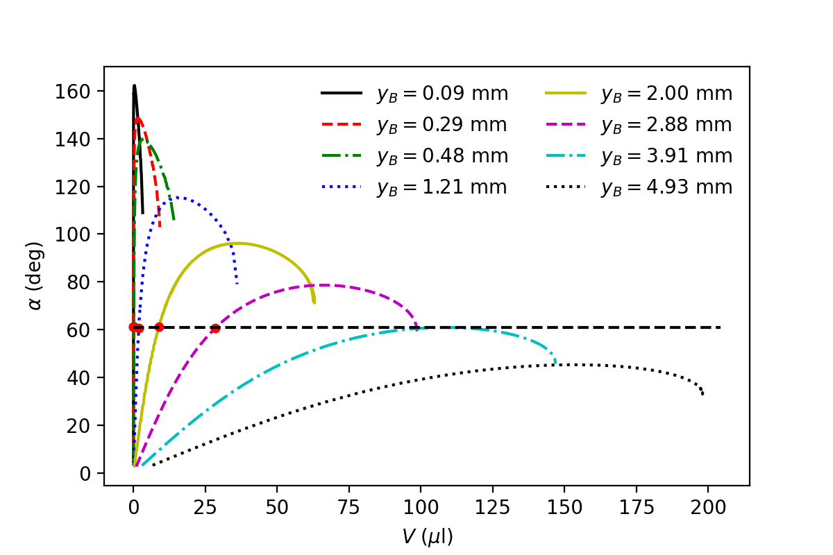
As shown in Fig. 18, for this particular example with , gravity induces a maximum in located at mm. Therefore, we can maximize the total volume of bubbles trapped by introducing patches with this radius.
In Fig. 19 we show the minimum contact angle achieved by the bubble during its evolution as a function of , for . Here, we skip the comparison with where the maximum contact angle should be .

For the maximum angle is found to be . Therefore, if we consider the bubble evolution on an patch with optimal radius as a series of stationary states, a hydrophobic patch with should be enough to pin the bubble until it reaches its maximum value. Here, is the value of at .
ACKNOWLEDGMENTS
Special thanks to M. Marengo for stimulating discussions. The authors also thank the European Space Agency (ESA), France and the Belgian Federal Science Policy (BELSPO) for their support in the framework of the PRODEX Programme. This research was partially funded by FNRS and Région Wallonne.
References
- [1] K H Ardron, G Giustini, and S P Walker. Prediction of dynamic contact angles and bubble departure diameters in pool boiling using equilibrium thermodynamics. International Journal of Heat and Mass Transfer, 114:1274–1294, 2017.
- [2] B Bourdon, E Bertrand, P Di Marco, M Marengo, R Rioboo, and J De Coninck. Wettability influence on the onset temperature of pool boiling: Experimental evidence onto ultra-smooth surfaces. Adv. Colloid Interface Sci., 221:34–40, 2015.
- [3] Y Dehai and Z Chen. A theoretical analysis on enthalpy of vaporization: Temperature-dependence and singularity at the critical state. Fluid Phase Equilib., 516:112611, 2020.
- [4] E A Farber and E L Scorah. Heat transfer to water boiling under pressure. Transactions of The ASME, 70:369–384, 1948.
- [5] A H Fatollahi and M Hajirahimi. Making sessile drops easier. arxiv.org/pdf/1304.6366, 2013.
- [6] N Kumar, P Ghosh, and P Shukla. Development of an approximate model for the prediction of bubble departure diameter in pool boiling of water. International Communications in Heat and Mass Transfer, 127:105531, 2021.
- [7] L D Landau and E M Lifshitz. Physique statistique. Editions MIR, Moscou, 1967.
- [8] M S Longuet-Higgins, B R Kerman, and K Lunde. The release of air bubbles from an underwater nozzle. Journal of Fluid Mechanics, 230:365–390, 1991.
- [9] S Nukiyama. The maximum and minimum values of the heat q transmitted from metal to boiling water under atmospheric pressure. International Journal of Heat and Mass Transfer, 9(12):1419–1433, 1966.
- [10] D W Oxtoby, H P Gillis, and A Campion. Principles of modern chemistry. https://chem.libretexts.org/.
- [11] H T Phan, N Caney, P Marty, S Colasson, and J Gavillet. Surface wettability control by nanocoating: The effects on pool boiling heat transfer and nucleation mechanism. International Journal of Heat and Mass Transfer, 52:5459–5471, 2009.
- [12] E Pitts. The stability of pendant liquid drops. Journal of Fluid Mechanics, 63:487–508, 1974.
- [13] J A Simmons, J E Sprittles, and Y D Shikhmurzaev. The formation of a bubble from a submerged orifice. European Journal of Mechanics-B/Fluids, 53:24–36, 2015.
- [14] F Villa, M Marengo, and J De Coninck. Towards a durable polymeric internal coating for diabatic sections in wickless heat pipes. Journal of Heat Transfer, 141(9):091802, 2019.
- [15] Y Xia, X Gao, and R Li. Influence of surface wettability on bubble formation and motion. Langmuir, 37(49):14483–14490, 2021.