Design and Characterization of Viscoelastic McKibben Actuators with Tunable Force-Velocity Curves
Abstract
The McKibben pneumatic artificial muscle is a commonly studied soft robotic actuator, and its quasistatic force-length properties have been well characterized and modeled. However, its damping and force-velocity properties are less well studied. Understanding these properties will allow for more robust dynamic modeling of soft robotic systems. The force-velocity response of these actuators is of particular interest because these actuators are often used as hardware models of skeletal muscles for bioinspired robots, and this force-velocity relationship is fundamental to muscle physiology. In this work, we investigated the force-velocity response of McKibben actuators and the ability to tune this response through the use of viscoelastic polymer sheaths. These viscoelastic McKibben actuators (VMAs) were characterized using iso-velocity experiments inspired by skeletal muscle physiology tests. A simplified 1D model of the actuators was developed to connect the shape of the force-velocity curve to the material parameters of the actuator and sheaths. Using these viscoelastic materials, we were able to modulate the shape and magnitude of the actuators’ force-velocity curves, and using the developed model, these changes were connected back to the material properties of the sheaths.
I Introduction
Originally introduced in the 1930s-1940s[1], and popularized by Joseph McKibben in the 1950s [2, 3, 4], pneumatic artificial muscles are a commonly studied soft robotic actuator and have been used in traditional rigid robotics [1, 5, 6], soft robotic platforms [7, 8], and wearable and assistive devices [9, 10, 11, 12, 13]. Consisting of an inner rubber bladder and an outer constraining mesh, the McKibben actuator is able to achieve high actuator strains and large force relative to its light weight [14]. McKibben actuators are of particular interest in bioinspired robotics and prosthetics because of their functional similarity to biological muscle in terms of contracting in response to activation and introducing compliance into the system. As a consequence, they can serve as first-order hardware models of skeletal muscle [15, 4, 14, 16]. Current experimental characterizations and models of these actuators tend to focus on their quasistatic properties, relating their inflation pressure, length, and axial force [3, 17, 18, 19, 20], but less attention has been given to their dynamics properties. These properties are important both to the design and modeling of the dynamics of a robotic system composed by these actuators and to the use of McKibben muscles as biomimetic actuators.
While few studies have been reported on the dynamic properties of McKibben actuators, those that have done so have often focused on the force-velocity relationship. For example, Tondu et al. performed isotonic quick-release experiments on McKibben actuators and showed that, for a particular combination of rubber bladder and mesh materials, the force-velocity relationship can resemble that of the Hill muscle model [14]. Other works have shown that the velocity-dependence of the McKibben actuator’s force is minimal compared to that of biological muscle[15, 21]. The authors instead augmented the muscle with parallel hydraulic damping elements to better mimic the biological tissue [15]. However, these solutions either rely on very particular woven mesh materials or large auxiliary equipment to tune the shape of the actuator’s force-velocity response.
In this work, we begin to investigate the force-velocity relationship of McKibben actuators and the ability to tune these relationships using simple viscoelastic material sheaths. Four different actuator architectures are investigated using actuators of three different diameters. The force-velocity response of these viscoelastic McKibben actuators (VMA) is measured using iso-velocity tests adapted from the muscle physiology literature [22]. To connect the measured force-velocity response to the material properties of the sheath and the mechanics of the underlying McKibben actuator, a simplified 1D model, consisting of parallel chains of standard linear solid elements (SLSEs), is formulated.
II Materials and Methods
II-A Actuator Design and Fabrication
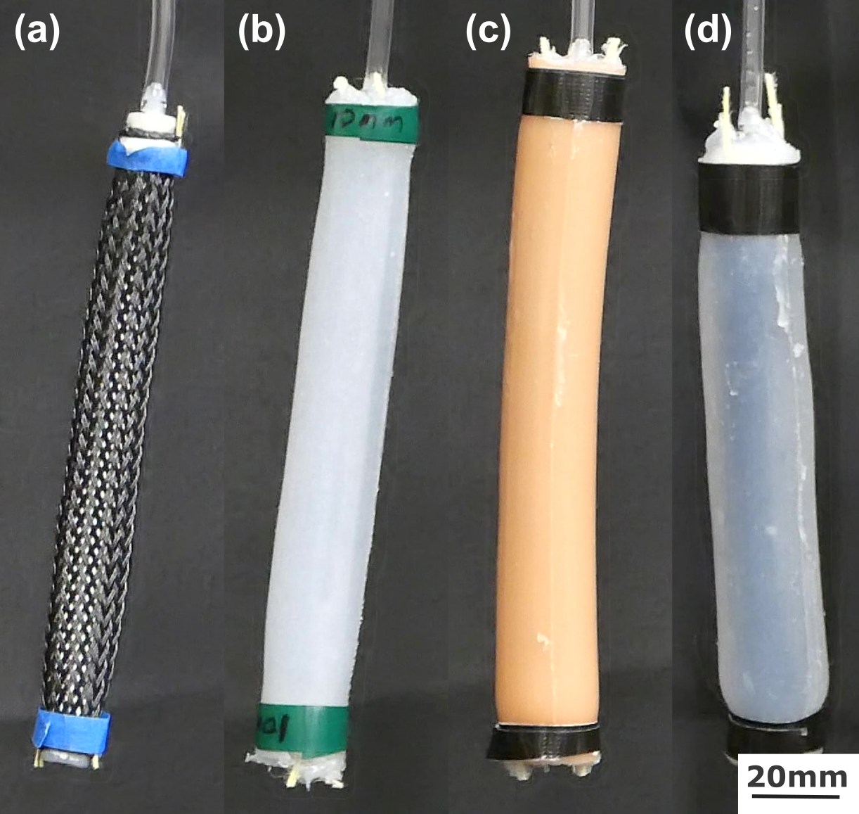
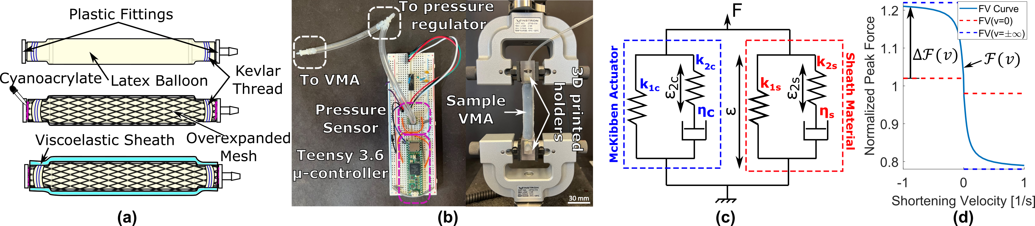
Each viscoelastic muscle actuator consists of a traditional McKibben actuator, serving as the contractile element, and a viscoelastic sheath around the McKibben, serving as a passive damper (Fig. 2a). Four 90 mm long McKibben actuators each of three different diameters (6 mm, 10 mm, 12 mm nominal mesh diameter) were fabricated. The design of the actuator was adapted from [7]. Briefly, a latex balloon inner bladder is connected to two barbed tube ends and is constrained by commercially available overexpanded cable meshes (PET Expandable Sleeving, Alex Tech). Kevlar fibers and cyanoacrylate glue were used to seal and connect the bladder and mesh to the end caps of the actuator.
Thin hollow sheaths of different viscoelastic and thixotropic materials were attached to the outside of the McKibben to act as the damping element of the actuator. To create the outer viscoelastic sheaths, 2 single-layered, concentric-cylindrical molds were 3D printed (Object 30, Stratasys), with inner diameters of 9 mm and 12 mm. For both diameters, the resulting sheath has a thickness of 2 mm. Polyurethane (Vytaflex, Smooth-On Inc.), Ecoflex-30 (Ecoflex 00-30, Smooth-On Inc.) and 5% Carbopol (Carbomer 940, Sanare) gel were used to fabricate the McKibben sheaths. For both the Ecoflex-30 and polyurethane sheaths, the liquid elastomer was prepared by mixing the 2-part polymer in a 1:1 ratio. The mixed polymer was placed in a vacuum chamber for 5 minutes to remove air bubbles. The 3D-printed molds were prepared by spraying a thin layer of mold release (Ease Release 200, Mann Release Technologies) on the inner surfaces of the mold. The elastomer was then injected into the mold and cured at room temperature (25∘C) for 12 hours. The Carbopol gel used in this project was adapted from [23]. First, 10g of Carbopol 940 powder (Carbomer) was mixed with 190g of deionized water. The mixture was then mechanically stirred for 4 hours. After stirring, 4g of 10M NaOH solution was added to the mixture. The new mixture was then mechanically stirred for 30 min. Finally, the gel was injected in between an Ecoflex-30 sheath and the McKibben actuator. The resulting sheaths were connected at the ends of the actuator using silicone epoxy (Sil-poxy, Smooth-On Inc.) and Kevlar threads.
The geometric and material parameters of all 12 actuators fabricated for experimental characterization, with and without sheaths, are provided in Table I. The fabricated length of each actuator was measured by a digital caliper. The Max Contraction Ratio is defined as the ratio of the length of the actuator at 20 psi to the length of the actuator at 0 psi (initial length).
II-B Experimental Characterization
Inspired by biological muscle testing [22], iso-velocity tests were performed at different pressure levels for all sample actuators on a universal material testing system (5969, Instron, 1 kN load cell). Inflation pressure was measured with a digital pressure sensor (ELVH-030G-HAND-C-PSA4, ALL SENSORS, maximum pressure 30 psi, resolution 0.1 psi) and recorded using a microcontroller (Teensy 3.6, PJRC). Two pairs of 3D printed holders were designed to hold both ends of the actuator and provide consistent friction between the actuator and the testing system. The force and length data from the universal material testing system and pressure data from the microcontroller were collected independently and synchronized later in MATLAB.
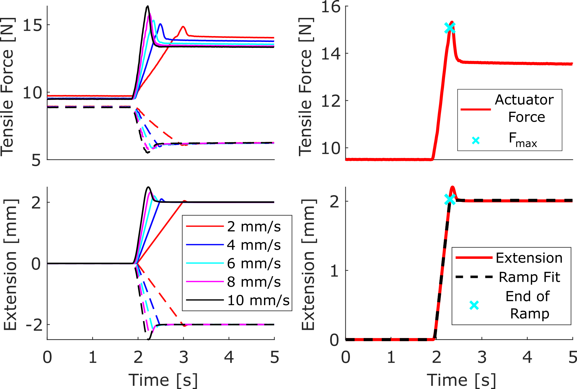
Iso-velocity tests (Fig. 4 (a)) were performed at five velocity magnitudes (2, 4, 6, 8, 10, all in mm/s) at 4 pressure levels (5, 10, 15, 20, all in psi). All five velocities were tested in a single session at a given pressure level. For a given pressure: the actuator was first held at its rest length in the testing system and pressurized to the desired level. After allowing the actuator force to reach steady state, the actuator was stretched between +4 and -4 mm at 0.01 mm/s for one cycle, returned to the unpressurized rest length, and again allowed to come to steady state. This was done to minimize preconditioning effects on the first ramp. For each velocity magnitude : the actuator was stretched 2 mm at mm/s and then held for 30 seconds. The actuator was then returned to the unpressurized rest length at 0.01 mm/s and held for 30 seconds. This same profile was then repeated at a velocity of mm/s. For 5 psi, only 1 mm of extension was applied, as shortening by more than 1mm from the unpressurized rest length would have led to shortening below the pressurized rest length of the actuators. Five repetitions of this full protocol were conducted for each actuator at each pressure and velocity.
| Sample | Mesh Diameter (mm) | IL* 1 STD (mm) | ML* 1 STD (mm) | Max Contraction Ratio (%) | Sheath Material | Sheath Diameter (mm) |
|---|---|---|---|---|---|---|
| Control1 | 6 | 88.50.9 | 68.30.6 | 22.8 | N/A | N/A |
| Control2 | 10 | 94.30.5 | 70.30.3 | 25.4 | N/A | N/A |
| Control3 | 12 | 91.50.4 | 67.20.1 | 26.6 | N/A | N/A |
| Ecoflex1 | 6 | 91.70.2 | 75.20.3 | 17.9 | Ecoflex-30 | 9 |
| Ecoflex2 | 10 | 89.70.4 | 70.20.5 | 21.8 | Ecoflex-30 | 9 |
| Ecoflex3 | 12 | 90.90.6 | 69.60.5 | 23.4 | Ecoflex-30 | 12 |
| Urethane1 | 6 | 91.21.0 | 70.60.5 | 21.7 | Poly-urethane | 9 |
| Urethane2 | 10 | 90.80.7 | 70.20.6 | 22.6 | Poly-urethane | 12 |
| Urethane3 | 12 | 89.70.4 | 68.30.8 | 23.9 | Poly-urethane | 12 |
| Carbopol1 | 6 | 92.50.3 | 72.70.3 | 21.4 | Carbopol+Ecoflex-30 | 12 |
| Carbopol2 | 10 | 93.80.4 | 70.20.5 | 21.9 | Carbopol+Ecoflex-30 | 12 |
| Carbopol3 | 12 | 86.40.3 | 64.80.4 | 24.9 | Carbopol+Ecoflex-30 | 12 |
-
•
IL*: Initial length. The length of sample actuator measured at 0 psi.
-
•
ML*: Minimum length. The length of sample actuators measured at 20 psi.
-
•
STD: Standard Deviation.
II-C Modeling
To relate changes in the experimental force-velocity curves to design parameters of the actuator materials, a simplified, 1D model was developed where both the McKibben actuator and polymer sheaths were treated as standard linear solid elements (SLSE) (Fig. 2c). The resulting force-velocity expressions are parameterized by mechanical properties of the actuator constituents and can therefore be used as a design tool to inform future designs. In this model, elastic elements are assumed to have a force linearly proportional to strain ( where the normalized stiffness has units [N]), and the viscous elements are assumed to have a force linearly proportional to the strain rate ( where the damping coefficient has units [Ns]). For the case of a single SLSE, the system force is given by:
| (1) |
where and are the stiffness of the parallel and series elastic elements, and and are the strains of the parallel and series elastic elements of the SLSE. For the actuators presented here only two SLSEs are included: a control McKibben (c) and the sheath (s). For each SLSE,
| (2) |
where is the damping coefficient of the series damper. Starting from steady state (), a constant strain rate ramp ( where has units [1/s]) yields a system force
| (3) |
For a fixed final applied strain , the peak system force is a function of the velocity (). Normalizing by the pre-extension, steady state force (), the force-velocity curve for the model can be written as:
| (4) |
where is the relative stiffness of the elastic elements and is the inverse of the time constant of the viscous arm (Fig. 2d). Here, is the sign function (). The height of the force-velocity curve above the discontinuity then takes the form:
| (5) |
Using this equation, the parameters and can be related to the shape of force-velocity curve. Specifically, the horizontal asymptote is given by:
| (6) |
and the velocity at which the force-velocity curve reaches can be approximated as:
| (7) |
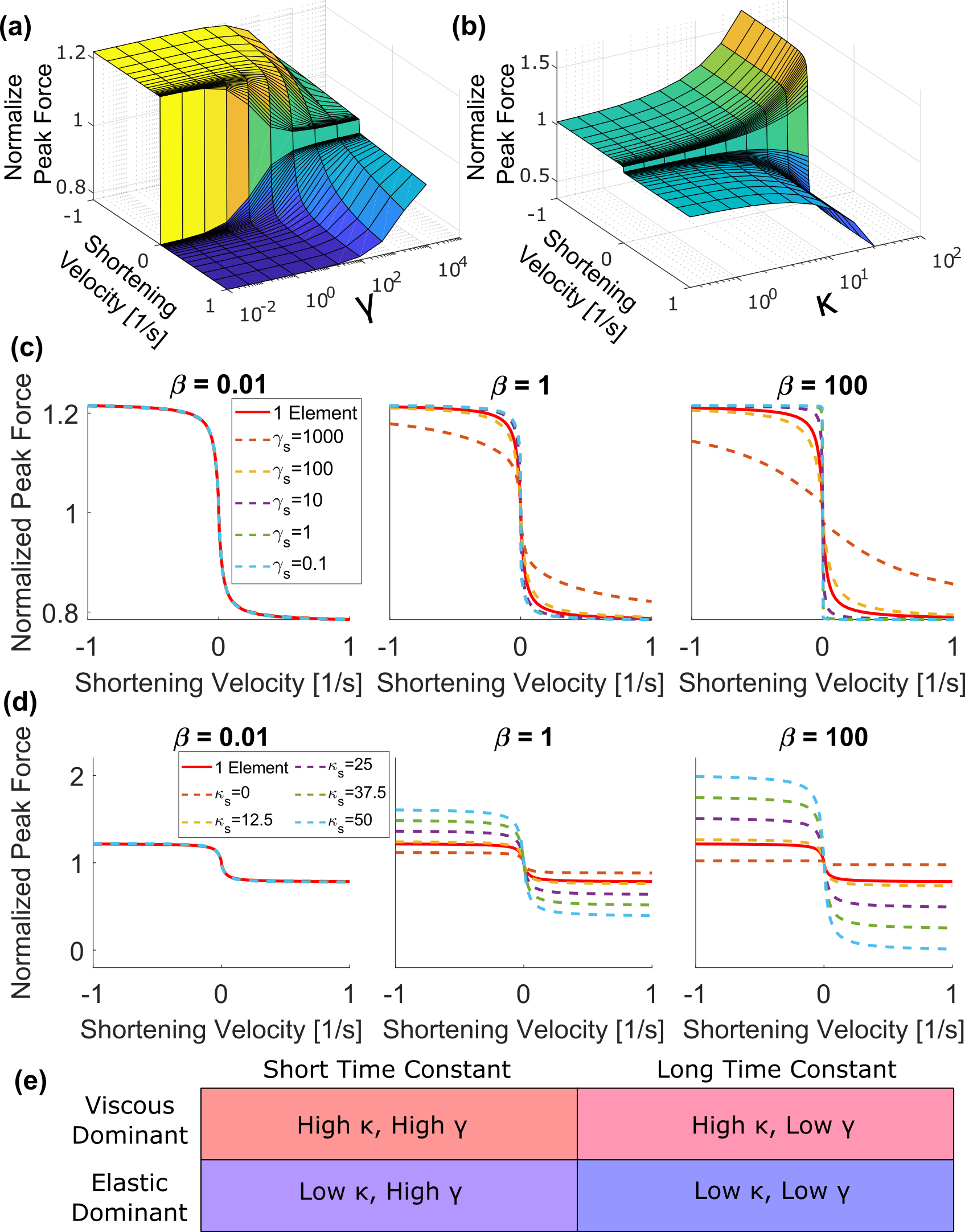
This approximation is valid within 5% for . Thus the height of the force-velocity curve is governed by and the steepness of the force-velocity curve is governed by (Fig.3a,b).
For the two-SLSE case (McKibben actuator and the sheath), similar relationships can be found. The shape of the force-velocity curve takes the form:
| (8) |
where and both take the form of from the 1 SLSE case. The height and steepness are governed by weighted averages of and :
| (9) |
and
| (10) |
where is the stiffness ratio of parallel elastic element to the McKibben parallel stiffness () in the different elements. With different combinations of , , and , the force-velocity response of the McKibben actuator can be tuned (Fig. 3 (c),(d)). These expressions can also be extended to any number of parallel SLSEs following this weighted average scheme.
II-D Analysis
Experimental force-velocity curves were compiled for each actuator and each pressure level using data measured during characterization experiments. Individual velocity ramps were identified and extracted from the larger experiment (Fig. 4a). The average velocity was found by fitting a piece-wise-linear ramp function to the extension data, the slope of which corresponds to the average velocity (Fig. 4b). The average velocity is then normalized by the pressurized rest length of the actuator to obtained the strain rate. The starting force () was calculated as the mean force during the two seconds prior to the start of the ramp. The peak force was taken as the force value when the extension first reached its target point. This was to avoid artifacts introduced by extension overshoot, which occurred at higher velocities. The peak force was then normalized by the starting force.
These experimental force-velocity curves were then used to obtain model parameters for the McKibben actuators and viscoelastic sheaths as functions of pressure. For all experiments, the values of , , , and in the model were calculated relative to the pressurized rest length of the actuator. First, for each control McKibben actuator at each pressure, and were fitted using a nonlinear least squares method (code generated by using MATLAB Curve Fitting Toolbox). Parameter initialization was chosen based on the Equations 6 and 7 for the horizontal asymptote and . Specifically, the normalized force from the tests were used as to approximate , and the data from the was used as the point to estimate . To fit , , and for each material, diameter, and pressure, the corresponding McKibben parameters were set as and and not optimized. The parameter was initialized to 1, and and were initialized following the same procedure as in the plain McKibben case. The same optimization process was then carried out for these three parameters.
III Results and Discussion
III-A Characterization
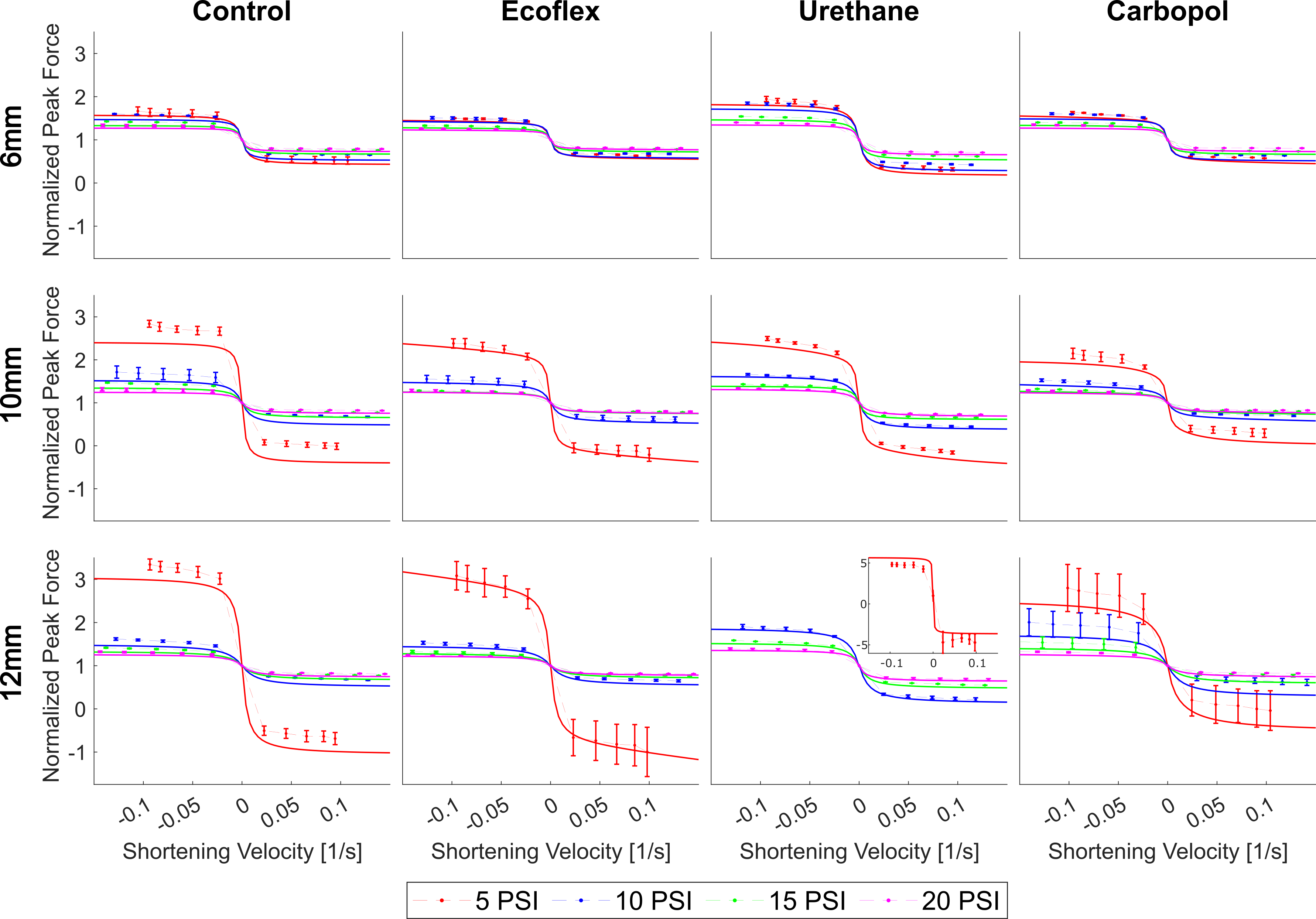
The force-velocity response of the twelve actuators was measured as a function of the pressure, sheath material, and mesh diameter (Fig. 5). In these figures, the normalized shortening velocity (negative of the extension strain rate) is reported in alignment with standard muscle physiology experiments. The shortening velocity is normalized by the pressurized rest length of the actuator (units of shortening velocity here are [1/s]). Common force-velocity features were found across all actuators. Unlike what is predicted in the model, all actuators showed an asymmetric force-velocity response, with a larger magnitude asymptote for extensions (negative shortening velocities) than for shortening. This reflects the nonlinear stiffness properties of the McKibben actuators that have been previously reported, with stiffness increasing with increased length [3]. Additionally, an increase in pressure led to a decrease in the height of force-velocity curve at all velocities and diameters, suggesting a more elastically dominant behavior at high pressures (Fig. 3b,e). However, the difference in height for a given pressure increase diminished with increasing pressure. This is most pronounced in the 10 and 12 mm diameter actuators at the 5 psi level. This could be related to changes in the contact state of the inner bladder. In these larger actuators, the bladder is not in full contact with mesh at lower pressures, but at higher pressures has made full contact. This low-pressure discrepancy being related to the contact state is also supported by the observation this discrepancy is not seen in the 6 mm actuators, where the mesh is in full contact with the actuator even at low pressures. However, the mechanism that causes this contact state to result in a more viscous-dominated response would require additional investigation.
The addition of the viscoelastic polymer sheaths was successful in altering the force-velocity response of the McKibben actuators. In the case of the 6 and 12 mm diameter urethane actuators, a more viscous-dominating response was achieved, with the height of the force-velocity curve being higher than the control actuator response at all pressures and velocities. The 10 mm urethane actuator showed a different response, with the height in much closer agreement with the control. This could be due to the 10 mm urethane actuator requiring a larger diameter sheath than the other 10 mm actuators. The larger diameter sheath was used because the smaller sheath diameter consistently ruptured at higher pressures. However, this meant that the sheath was less in contact with the underlying McKibben than in the 6 and 12 mm cases and was thus less engaged. Conversely, the Ecoflex sheath led to a decrease in the height of the force-velocity curve in extension for all diameters and pressure, showing a more elastic-dominant response. In shortening, the Ecoflex actuators showed closer agreement with the control actuators. Finally, the effect of the Carbopol actuators varied. For the 6 mm actuator, almost no change was seem from the control actuator. In the 10 mm actuator, the response was much closer to that of the Ecoflex, showing a more elastic-dominant response. In the 12 mm case, the effect varied with pressure and direction of motion, with an increased height seen at 10 and 15 psi in extension, but no difference seen at 20 psi or in shortening at 10, 15 or 20 psi.
This characterization is limited in a number of ways. The force-velocity curve, while relevant to the actuator in terms of its role as a model of skeletal muscle, is only one metric by which to determine these actuators’ dynamic properties or the ability of these material sheaths to tune them. More complete characterization will require cyclic testing at various speeds to determine hysteresis as a function of velocity. Additionally, the minimum extension rate of 2 mm/s was near the horizontal asymptote for many actuators, resulting in poor characterization of the high slope region of the force-velocity curve near . A more complete investigation of the force-velocity curve will require lower velocities to be incorporated. These higher test rates also resulted in extension and shortening overshoot in the tests, which made the calculation of the peak force and the following force decay more challenging. These overshoots would be minimized with lower velocity tests.
III-B Modeling
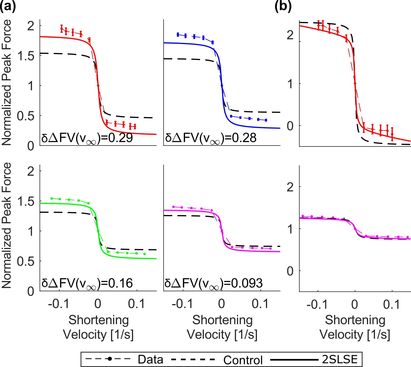
The presented model was able to successfully capture major trends in the experimental force-velocity curves ( for all actuators and pressures), and the changes in the VMA curve relative to the control curves can be explained through the model parameters. For example, in all actuators, an increase in pressure leads to a decrease in the height of the force-velocity curve. This is expected under this model, as increasing the pressure of the McKibben actuator increases its stiffness [3], and this increased stiffness results in a lower and thus . This model can also be used to explain changes in the force-velocity curves associated with the material sheaths (Fig. 6). Based on preliminary materials testing, the urethane sheath would fall into the viscous dominant, long time constant class, and Ecoflex would fall into the elastic dominant, short time constant class (relative to the McKibben actuator). Therefore, we would expect that the urethane would cause an increase in the height of the force-velocity curve (Fig. 3e). However, with increased pressure, the relative stiffness of the McKibben to the urethane sheath increase (decreasing ), so we would expect this difference to decrease with increased pressure as the weighted average begins to favor the McKibben actuator (Fig. 6a). For the Ecoflex sheath, the relatively shorter time constant would lead to a high slope of the force-velocity curve, which is seen at low pressures (Fig. 6b). However, as with the urethane sheath, an increased pressure leads to the McKibben properties dominating once again.
While this model can capture many of the trends in the data, there are some limitations in its accuracy and predictive power. Both the McKibben actuators and the sheath materials are non-linearly elastic, with their stiffness increasing with increased strain. This results in an asymmetrical force-velocity curve, with a larger response for extension (negative shortening velocity) relative to shortening at the same rate. This cannot be captured by the linear springs in the proposed model. As a consequence, the model fits tend to under-predict extension responses and to over-predict shortening responses. Furthermore, the asymmetry also results in high parameter uncertainty. Improvements can be made through the inclusion of nonlinear spring elements and more appropriate models of the McKibben actuator at the cost of decreased interpretability of the model parameters. Additionally, the optimized sheath parameters tend to vary with pressure, whereas it would be expected that they would be pressure-independent for linear materials. However, a pressure dependence would be expected for nonlinear materials, as the McKibben actuator’s pressure will determine the deformation state of the sheath material. In the future, this pressure dependence could be incorporated into the model as well, but it would require 3D geometric information about the actuator. Both of these issues could be addressed by incorporating a more complete quasi-static McKibben model [3, 17, 9] to capture the strain stiffening of the McKibben actuators and provide the geometry needed to estimate the sheath stiffness pressure dependence.
Finally, this model only includes damping from standard dash-pot elements. However, previous work has shown that a velocity dependence in McKibben actuators can actually come from non-linear friction interactions in the mesh material[14] and Coulomb friction between the bladder material and the sheath [21, 4]. Future model development should incorporate such friction into a more complete model of the McKibben to replace one of the SLSEs in this model.
IV Conclusion and Future Works
This work presents the characterization and modeling of the force-velocity relationships of viscoelastic McKibben actuators (VMA). These VMAs consist of a standard McKibben actuator surrounded by a viscoelastic polymer sheath. Iso-velocity experiments were performed to measure the force-velocity response of these actuators, and a simplified 1D model was developed to relate the shape of these experimental force-velocity curves to the material properties of the actuators. Using these polymer sheaths, we were able to successfully augment the force-velocity response of a standard McKibben, changing either its asymptotic height or its slope. The 1D model performed well in capturing the trends in these force-velocity curves, but missed key features, including the asymmetry in extension/shortening and the pressure dependence of sheath properties.
Future works on these actuators will include iso-velocity tests at slower speeds to further investigate the steep portion of the force-velocity curve near the discontinuity. Additionally, to increase the predictive power of the model, more accurate quasistatic models of the McKibben’s length-pressure-force properties will be implemented to replace the linear spring element. This will also require the measurement of the actuator geometry during quasi-static testing. Geometric information from these models will be used to capture the deformation-dependent properties of the sheath materials as well. With better predictive power, these models can be used as a design tool for creating actuators with a desired force-velocity response. Future characterization will also include cyclic testing of the actuators at various speeds to more robustly investigate their dynamic properties. The work presented here lays the foundation for the fabrication and design of pneumatic actuators with tunable force-velocity dynamics for broad applications in bioinspired and biomimetic robotics.
Acknowledgements
This work was supported in part by the National Science Foundation (NSF) through grant no. FRR-2138873, and in part by NSF DBI-2015317 as part of the NSF/CIHR/DFG/FRQ/UKRI-MRC Next Generation Networks for Neuroscience Program. Any opinions, findings, and conclusions expressed in this material are those of the authors and do not necessarily reflect the views of the NSF.
References
- [1] F. Daerden, D. Lefeber et al., “Pneumatic artificial muscles: actuators for robotics and automation,” European journal of mechanical and environmental engineering, vol. 47, no. 1, pp. 11–21, 2002.
- [2] E. Hawkes, C. Majidi, and M. Tolley, “Hard questions for soft robotics,” Science Robotics, vol. 6, no. 53, 2021.
- [3] B. Tondu, “Modelling of the McKibben artificial muscle: A review,” Journal of Intelligent Material Systems and Structures, vol. 23, no. 3, pp. 225–253, 2012.
- [4] C.-P. Chou and B. Hannaford, “Measurement and modeling of mckibben pneumatic artificial muscles,” IEEE Transactions on Robotics and Automation, pp. 90–102, 1996.
- [5] N. Delson, T. Hanak, K. Loewke, and D. N. Miller, “Modeling and implementation of McKibben actuators for a hopping robot,” 2005 International Conference on Advanced Robotics, ICAR ’05, Proceedings, vol. 2005, pp. 833–840, 2005.
- [6] S. Kurumaya, K. Suzumori, H. Nabae, and S. Wakimoto, “Musculoskeletal lower-limb robot driven by multifilament muscles,” ROBOMECH Journal, vol. 3, no. 1, pp. 1–15, 2016.
- [7] K. Dai, R. Sukhnandan, M. Bennington, K. Whirley, R. Bao, L. Li, J. P. Gill, H. J. Chiel, and V. A. Webster-Wood, “Slugbot, an aplysia-inspired robotic grasper for studying control,” Living Machines, 2022.
- [8] A. A. Faudzi, N. I. Azmi, M. Sayahkarajy, W. L. Xuan, and K. Suzumori, “Soft manipulator using thin McKibben actuator,” IEEE/ASME International Conference on Advanced Intelligent Mechatronics, AIM, vol. 2018-July, pp. 334–339, 2018.
- [9] F. Connolly, C. Walsh, and K. Bertoldi, “Automatic design of fiber-reinforced soft actuators for trajectory matching,” Proceedings of the National Academy of Sciences, vol. 114, no. 1, pp. 51–56, 2016.
- [10] M. Tschiersky, E. E. Hekman, D. M. Brouwer, J. L. Herder, and K. Suzumori, “A Compact McKibben Muscle Based Bending Actuator for Close-to-Body Application in Assistive Wearable Robots,” IEEE Robotics and Automation Letters, vol. 5, no. 2, pp. 3042–3049, 2020.
- [11] S. Koizumi, T. H. Chang, H. Nabae, G. Endo, K. Suzumori, M. Mita, K. Saitoh, K. Hatakeyama, S. Chida, and Y. Shimada, “Soft Robotic Gloves with Thin McKibben Muscles for Hand Assist and Rehabilitation,” Proceedings of the 2020 IEEE/SICE International Symposium on System Integration, SII 2020, pp. 93–98, 2020.
- [12] L. Rosalia, C. Ozturk, J. Coll-Font, Y. Fan, Y. Nagata, M. Singh, D. Goswami, A. Mauskapf, S. Chen, R. A. Eder, E. M. Goffer, J. H. Kim, S. Yurista, B. P. Bonner, A. N. Foster, R. A. Levine, E. R. Edelman, M. Panagia, J. L. Guerrero, E. T. Roche, and C. T. Nguyen, “A soft robotic sleeve mimicking the haemodynamics and biomechanics of left ventricular pressure overload and aortic stenosis,” Nature Biomedical Engineering, vol. 6, pp. 1134–1147, 2022.
- [13] Y.-L. Park, B.-r. Chen, C. Majidi, R. J. Wood, R. Nagpal, and E. Goldfield, “Active modular elastomer sleeve for soft wearable assistance robots,” in 2012 IEEE/RSJ International Conference on Intelligent Robots and Systems, 2012, pp. 1595–1602.
- [14] B. Tondu and S. D. Zagal, “McKibben artificial muscle can be adapted to be in accordance with the Hill skeletal muscle model,” Proceedings of the First IEEE/RAS-EMBS International Conference on Biomedical Robotics and Biomechatronics, 2006, BioRob 2006, vol. 2006, no. 3, pp. 714–720, 2006.
- [15] G. K. Klute, J. M. Czerniecki, and B. Hannaford, “McKibben artificial muscles: Pneumatic actuators with biomechanical intelligence,” IEEE/ASME International Conference on Advanced Intelligent Mechatronics, AIM, pp. 221–226, 1999.
- [16] S. Gollob, J. Poss, G. Memoli, and E. Roche, “A multi-material, anthropomorphic metacarpophalangeal joint with abduction and adduction actuated by soft artificial muscles,” IEEE Robotics and Automation Letters, vol. 7, no. 3, pp. 5882–5887, 2022.
- [17] A. Al-Ibadi, S. Nefti-Meziani, and S. Davis, “Efficient structure-based models for the McKibben contraction pneumatic muscle actuator: The full description of the behaviour of the contraction PMA,” Actuators, vol. 6, no. 4, 2017.
- [18] G. Olsen, H. Manjarrez, J. Adams, and Y. Mengüç, “Experimentally identified models of mckibben soft actuators as primary movers and passive structures,” Journal of Mechanisms and Robotics, vol. 14, no. JMR-20-1425, pp. 011 006–1–011 006–15, 2022.
- [19] C. S. Kothera, M. Jangid, J. Sirohi, and N. M. Wereley, “Experimental characterization and static modeling of McKibben actuators,” Journal of Mechanical Design, Transactions of the ASME, vol. 131, no. 9, pp. 0 910 101–09 101 010, 2009.
- [20] T. Hassan, M. Cianchetti, M. Moatamedi, B. Mazzolai, C. Laschi, and P. Dario, “Finite-element modeling and design of a pneumatic braided muscle actuator with multifunctional capabilities,” IEEE/ASME Transactions on Mechatronics, vol. 24, no. 1, pp. 109–119, 2019.
- [21] C. P. Chou and B. Hannaford, “Static and dynamic characteristics of McKibben pneumatic artificial muscles,” Proceedings - IEEE International Conference on Robotics and Automation, no. pt 1, pp. 281–286, 1994.
- [22] S. N. Yu, P. E. Crago, and H. J. Chiel, “Biomechanical properties and a kinetic simulation model of the smooth muscle I2 in the buccal mass of Aplysia,” Biological Cybernetics, vol. 81, no. 5-6, pp. 505–513, 1999.
- [23] T. J. Hinton, A. Hudson, K. Pusch, A. Lee, and A. W. Fienberg, “3d printing pdms elastomer in a hydrophilic support bath via freeform reversible embedding,” ACS Biomaterials Science & Engineering, 2016.