Sequential Structure and Control Co-Design of Lightweight Precision Stages with Active Control of Flexible Modes
Abstract
Precision motion stages are playing a prominent role in various manufacturing equipment. The drastically increasing demand for higher throughput in integrated circuit (IC) manufacturing and inspection calls for the next-generation precision stages that have light weight and high control bandwidth simultaneously. In today’s design techniques, the stage’s first flexible mode is limiting its achievable control bandwidth, which enforces a trade-off between the stage’s acceleration and closed-loop stiffness and thus limits the system’s overall performance. To overcome this challenge, this paper proposes a new hardware design and control framework for lightweight precision motion stages with the stage’s low-frequency flexible modes actively controlled. Our method proposes to minimize the resonance frequency of the controlled mode to reduce the stage’s weight, and to maximize that of the uncontrolled mode to enable high control bandwidth. In addition, the proposed framework determines the placement of the actuators and sensors to maximize the controllability/observability of the stage’s controlled flexible mode while minimizing that of the uncontrolled mode, which effectively simplifies the controller designs. Two case studies are used to evaluate the effectiveness of the proposed framework. Simulation results show that the stage designed using the proposed method has a weight reduction of more than 55% compared to a baseline stage design. Improvement in control bandwidth was also achieved. These results demonstrate the effectiveness of the proposed method in achieving lightweight precision positioning stages with high acceleration, bandwidth, and precision.
Index Terms:
Precision positioning systems, control co-design, structure controlI Introduction
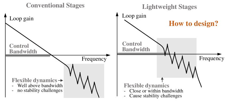
High-precision positioning stages are playing a critical role in a wide range of manufacturing and inspection tools such as photolithography scanners [2] and MEMS inspection systems [1]. The drastically growing demand for higher throughput in semiconductor manufacturing necessitates the next-generation precision motion stages with higher acceleration capability while maintaining excellent positioning accuracy and high control bandwidth [9]. Creating new lightweight precision positioning stages is critical to achieve this goal. However, as the stage’s weight reduces, its structural resonance frequencies will decrease to near or even within the control bandwidth (Fig. 1), which limits the stage’s control bandwidth and positioning accuracy, and can even cause stability challenges [8].
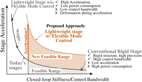
In the past decade, a number of research and engineering efforts have studied the design and control for lightweight precision positioning stages. For example, Laro et al. [7] presented an over-actuation approach to place actuators/sensors at the stage’s nodal locations to prevent the flexible dynamics from being excited by the feedback loops. Oomen et al. [9] proposed a system identification and robust control framework for wafer stages, which provides a systematic approach to create controller designs for stages exhibiting low-frequency flexible dynamics. Although effective, these studies mostly investigate the motion control for flexible stages, and the synergy between the structure design and controller design is not fully exploited. In recent years, the hardware-control co-design, or control co-design (CCD) [6], has been studied for the lightweight precision positioning stages, aiming at enabling a synergistic structure-control design method for precision positioning stages. For example, Van der Veen et al. [13] studied the integrated topology and controller optimization for a simple 2D motion stage structure. Delissen et al. [3] presented a topology-optimized wafer stage fabricated via metal additive manufacturing. In a recent study, Wu et al. [15] presented a nested CCD formulation of for lightweight precision stages with controller design constraints explicitly considered. Despite these advances, we make a key observation that in these prior lightweight precision stages designs, the first resonance frequency of the stage structure sets an upper limit for the achievable control bandwidth. This fact enforces a fundamental trade-off between the stage’s bandwidth and acceleration as illustrated in Fig. 2. Fundamental advances in the stage’s mechatronic design must be made to break this trade-off and thus enable stages with improved overall performance.
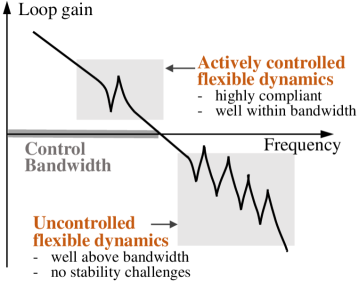
Aiming at overcoming the aforementioned trade-off and thus creating new lightweight stages that can simultaneously have high acceleration and high closed-loop stiffness, this paper presents a sequential structure and control design framework where the low-frequency flexible modes of the stage are under active control. This approach has been explored in van Herpen et al. [14] where additional actuators and sensors are introduced for a lightweight stage to enhance the control bandwidth. However, in [14], the control for flexible dynamics is not considered in the stage’s structural design phase, which limits the achievable performance. In our work, to facilitate the controller design, we propose to minimize the resonance frequency of the stage’s mode being controlled and to maximize the resonance frequency of the uncontrolled mode. The target control bandwidth of the stage is in between the resonance frequencies, as shown in Fig. 3. We envision that this formulation will remove material in the stage’s structure to allow compliance in the actively-controlled modes thereby breaking the trade-off in lightweight stages, as shown in Fig. 2. With the stage’s structure designed, we further propose to use an optimization method to compute the best actuator/sensor placement. Our hypothesis is that maximizing the controllability/observability of the actively-controlled flexible modes while minimizing that of the uncontrolled modes will deliver the best positioning performance with reasonable control signal magnitude. Two case studies are simulated to evaluate the effectiveness of the proposed approach, where a stage weight reduction of is demonstrated compared to a baseline case. These results demonstrate the potential of the proposed lightweight precision stage design framework.
The rest of the paper is organized as follows. Section II describes the problem statement. Section III presents the proposed design framework for the lightweight precision positioning stage. Section IV shows the simulation evaluations with two case studies. Conclusion and future work are summarized in Section V.
II Problem Statement
The dynamics of a precision positioning stage considering its flexible structural behaviors can be described by
| (1) | ||||
where is a vector of state variables of both rigid-body displacements and flexible displacements in the modal coordinate, , , are the mass, damping and stiffness matrices, respectively, is the vector of control signals, is a vector of measurement signals, is the input matrix which maps the control input to corresponding states, is the output matrix which maps state variables to measurements, is a vector of stage’s geometric design parameters, and , are the vectors of actuator and sensor locations, respectively.
The design optimization problem for a lightweight precision stage described by (1) aims at finding a set of hardware design parameters , , and and a controller design that can minimize the stage’s weight while maximizing the control bandwidth, meanwhile satisfying certain robustness criteria.
III Sequential Hardware and Control Optimization Framework
This section presents a sequential framework of designing the hardware and controller for lightweight stages with their low-frequency flexible modes actively controlled. In the first step, an optimization problem that determines the stage’s geometric parameter is formulated to facilitate the active control for the stage’s low-frequency flexible modes. In the second step, an optimization is performed to determine the location of actuators and sensors. Finally, feedback controllers are synthesized for the designed stage to control the stage’s motion as well as the low-frequency flexible modes. The three steps are introduced in detail in the following sections.
III-A Stage Geometry Design Optimization
In a lightweight precision stage with active control for low-frequency flexible modes, the stage’s geometry design optimization is formulated as
| (2) | ||||
Here, the objective function represents the stage’s weight, is a vector for the stage’s geometric parameters, is the -th modal frequency with its corresponding vibration mode actively controlled, and is the -th resonance frequency where the corresponding mode shape is not controlled. is the upper bound for the actively-controlled resonance frequencies, and is the lower bound for the uncontrolled resonance frequencies. and are the lower and upper bounds for the stage’s geometric parameter, respectively.
With the stage structure design optimization formulation (2), the stage’s flexible modes under active control are having resonance frequencies below , and that of the uncontrolled modes are beyond . Such an optimization process can enforce material removal in the stage’s structure to allow for compliance in the actively-controlled flexible modes, and add material to stiffen the uncontrolled modes.
Remark III.1
The selection of and are highly important and determine the system’s dynamic behavior. The system’s target control bandwidth must be between and , and sets the new upper bound for the achievable control bandwidth for the lightweight precision stage with actively controlled flexible modes, as illustrated in Fig. 2.
To facilitate controller design while maintaining design feasibility, the values of and need to be selected according to the target control bandwidth, for example and , where is the target bandwidth. This method, although robust, may lead to a relatively conservative stage design. To fully evaluate the feasible design range in Fig. 2, the value of needs to be swept while considering the actuator/sensor positioning, which will be introduced in Section IV-B.
III-B Actuator and Sensor Placement
The actuator and sensor placement optimization problem for the proposed lightweight stage with active flexible mode controlled can be formulated as
| (3) |
| (4) |
where and are vectors of actuator and sensor placement parameters, respectively; and are the design domains for actuator/sensor locations, and is a positive user-defined weighting constant. and are the controllability and observability grammians of -th flexible mode, respectively, which can be calculated as
| (5) |
where is the mass-normalized mode shape of -th flexible mode, and are the force and measurement assembling matrices, is the modal damping ratio, and is the -th resonance natural frequency. The controllability/observability grammians and quantitatively evaluate the controllability/observability of the corresponding flexible mode in the control system, which will reflect on the peak resonance magnitude in the system’s frequency response.
With actuator/sensor placement optimization formulation in (3) and (4), our goal is to maximize the controllability/observability for the actively-controlled modes to reduce the required controller gain, and to minimize those of the uncontrolled modes to reduce their coupling with the control systems. The value of provides a trade-off between the two design goals: a low value in emphasizes reducing the needed controller gain for actively-controlled modes, and a high value in emphasizes reducing the cross-talk between uncontrolled modes and controlled modes.
III-C Feedback Control Design
| Parameter | Description | Typical Value |
|---|---|---|
| Desired bandwidth [rad/s] | – | |
| PID frequency ratio | 0.3 | |
| Proportional gain | – | |
| Integrator frequency | ||
| Differentiator frequency | ||
| Lowpass filter frequency | ||
| Lowpass filter damping ratio | 0.7 |
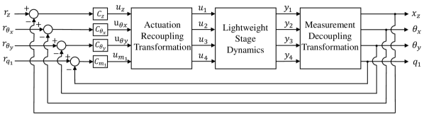
With the stage’s structure and actuator/sensor locations determined, the plant dynamics of the stage can be found. Feedback controllers can be designed for each degree of freedom (DOF) to enable precision positioning and disturbance rejection. Figure 4 shows a block diagram for the control loop for a lightweight stage with three rigid-body DOFs and one flexible mode under active control. Here, the lightweight stage plant dynamics can be obtained from solving (2), (3), and (4). The sensor measurements are transformed to individual DOFs via a measurement decoupling transformation. Four single-input, single-output (SISO) feedback controllers can then be designed for four decoupled channels assuming the cross-coupling between different DOFs is negligible. For each DOF, a fixed-structure SISO controller is selected following reference [5] as
| (6) | ||||
where the controller parameters are described in Table I. This controller design follows reference [2, 4] where all the controller parameters except the controller gain can be determined by a target control bandwidth . This approach effectively simplifies the parameter tuning process. The proportional gain and the target bandwidth are determined such that the control bandwidth is maximized while satisfying a robustness criteria[10] of
| (7) |
where is the closed-loop sensitivity function of the -th channel as . With the control effort signals for each channel computed, an actuation recoupling transformation is used to map the control signals to individual actuators.
IV Simulation Evaluation
Two case studies are simulated to evaluate the potential and effectiveness of the proposed lightweight precision stage design method. Case study #1 considers a simple rib-enhanced stage structure with arbitrary sensor/actuator placements, aiming at demonstrating the impact of the selection of the weighting variable on controller design. Case study #2 implements the proposed framework for a practical lightweight planar motor stage with the actuator’s weight and location constraints considered. The performance of both case studies compared to that of a baseline stage design without flexible mode control for evaluation.
IV-A Case study #1
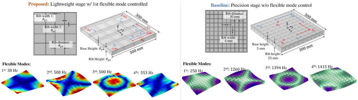
Figure 5 shows the diagrams of the stage structure being considered, which shows a rib-reinforced structure made of 6061-T6 aluminum alloy of mm mm in size. The coordinate system being used is also shown in Fig. 5. Herein, the rigid-body motion of the stage in three DOFs, including vertical translation (), roll (), and pitch () are actively controlled. In addition, the proposed stage also actively controls its first vibration mode, and the baseline stage has no control for flexible modes. Therefore, three actuators and three sensors are used for the baseline stages for exact constraint, while the proposed case uses four actuators and four sensors. The geometric parameters and the actuator/sensor location parameters and are also shown in Fig. 5.
Due to the geometric complexity of the ribbed stage structure, analytical models are not sufficient to capture its structural dynamics accurately. In this work, finite element (FE) simulation (with COMSOL Multiphysics) is used to simulate the stage’s spatial-temporal behavior. In the stage geometry optimization problem (2) formulation for the proposed stage in Fig. 5, to facilitate controller design with a target control bandwidth of , the values of and are selected as and , respectively. In addition, the rib width and base height are constrained to be larger than for the sake of manufactuability. With the stage geometry optimization problem (2) fully formulated, the Optimization Module in COMSOL Multiphysics is selected to solve the problem, where an iterative method for derivative-free constrained optimization COBYLA [11] is employed. The resultant stage resonance frequencies and mode shapes are illustrated in Fig. 5.
The actuator/sensor placement optimization problems (3)-(4) are then solved for the optimized structure. In case study #1, the actuator/sensor location range is over the entire top surface of the stage, i.e., . The normalized mode shapes over all mesh nodes for the stage and their corresponding natural frequencies can be obtained from the FE simulations. For each node location within placement domain, let or or and thus the actuation/sensing matrices or can be found. A modal damping of is assumed for all modes, and the grammians (5) for each mode can be computed. A direct search algorithm is utilized to find the optimal actuator/sensor locations.
Remark IV.1
When and the placement domain of actuators and sensors being identical, i.e., , the optimal solution for both (3) and (4) will be identical too. Therefore, the optimal configuration is a “collocated” case with the actuator and sensors configured at the same location [12]. In addition, the stage structure being considered is symmetrical about the and axes. Therefore, the optimal actuator/sensor location will be also symmetrical as shown in Fig. 5. These two facts significantly simplify the numerical computation required for the actuator/sensor placement optimization problems.
With the stage’s geometric design and the placement of actuator/sensor decided, we are able to extract the state-space models for the proposed lightweight stage from the FE simulations. The system’s undamped dynamics can be written as
| (8) | ||||
where is the vector of displacement of all nodes in the FE simulation, is the number of nodes from mesh setting, are the mass and stiffness matrices, respectively, and and are the input and output matrices determined by the actuator and sensor locations. Note that the dimension of the FE-computed system dynamics (8) is typically very large () especially when a fine mesh is used in the simulation. To overcome this problem, the system dynamics (8) is transformed into the modal coordinate as
| (9) | ||||
where is the decoupled modal state vector, is an matrix where represents the vector of corresponding -th mode shape with mass matrix normalized, i.e. , is the diagonal stiffness matrix, and and are decoupled input and output matrix, respectively. In this decoupled coordinate, we can reduce the model order by truncating high-frequency vibration modes. We keep only the 3 rigid-body modes and first 10 flexible modes in this paper. Such model is able to capture the system dynamics accurately up to , which is sufficient for controller design. Then, a modal damping term is introduced into the (9), and a reduced-order model in the form of (1) can be derived. Finally, the actuation signals and measurement signals are transformed into the decouple DOFs as shown in Fig. 4.
As is stated in Section III-B, the weighting parameter in (3)-(4) provides a balance between the need to have small control gains and the need to decouple controlled modes and uncontrolled modes. In this case study, (3)-(4) are solved for the stage structure with a varying value of , and the resultant actuator/sensor locations are shown in Fig. 6. Here in Fig. 6, the red crosses represent the optimal actuator/sensor locations with different values (note that the actuators and sensors are collocated), and the blue lines represent the nodal lines of the stage’s second to fourth vibration modes. Figure 7 shows the decoupled plant frequency responses of the proposed lightweight stage with actuator/sensor location optimized under different values of . Several selections of the value are discussed as below.
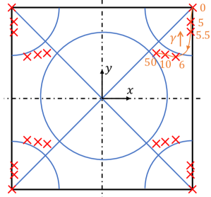
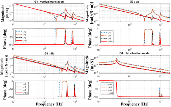
(a): : With , the optimal actuator/sensor locations are at the corners of the stage (Fig. 6), where the first vibration mode’s modal displacement is maximized. This is because with we are only considering the need to maximize the controllability/observability of the actively-controlled modes, and not considering the effects of high-frequency uncontrolled modes. This is confirmed by the plant frequency response shown in Fig. 7 with (blue dashed line), where the last channel of the plant dynamics (the stage’s first flexible mode) is having high magnitude. However, this design results in strong coupling between the stage’s rigid body motion and the uncontrolled flexible modes (e.g. the second mode at 500 Hz).
(b): . As increases, the actuator/sensor locations move towards the the nodal location of the stage’s uncontrolled flexible modes, as shown in Fig. 6. This is also confirmed by the plant frequency responses shown in Fig. 7: as increases, the peak of uncontrolled flexible modes decreases, while the magnitude of the last channel in the plant dynamics (the stage’s first flexible mode) reduces as well.
From the discussions above, it can be concluded that a large value in is beneficial for obtaining high control bandwidth at the cost of needing a higher controller gain in the flexible mode control. Therefore, the value of should be selected as its maximum allowed value to produce an acceptable plant magnitude in the actively controlled flexible mode. In this case study, (i.e. the plant as red solid lines in Fig. 7) is selected to enable a high control bandwidth. The resultant optimal actuator/sensor locations are close to the nodal positions of the uncontrolled flexible modes, see Fig. 6. Finally, four SISO controllers in the form of (6) are designed for each actively-controlled DOFs, with a target control bandwidth of .
| Baseline Design | Proposed Design | |
|---|---|---|
| Stage weight | 2.31 kg | 0.34 kg |
| 1st res. freq. | 250 Hz | 38 Hz |
| 2nd res. freq. | 1260 Hz | 500 Hz |
| bandwidth | 100 Hz | 100 Hz |
| bandwidth | 26 Hz | 100 Hz |
| Max sensitivity | 1.89 | 1.84 |
To evaluate the effectiveness of our proposed design method, a baseline lightweight precision stage as illustrated in Fig. 5 is used for comparison. This baseline stage lightweight stage does not have active control for its flexible modes, and only has the rigid body motions under feedback control. Three actuators and three sensors are used to achieve exact constraint in the stage actuation and control. In such a design, the first resonance frequency of the stage structure places an upper limit to the achievable control bandwidth. With a target control bandwidth of 50 Hz, the geometric parameters of the baseline stage are designed such that the first resonance frequency of the stage structure is above 250 Hz (i.e. of the target bandwidth). Similarly, SISO controllers in the form of (6) are designed for all decoupled DOFs under active control such that the robustness criteria 7 is satisfied.
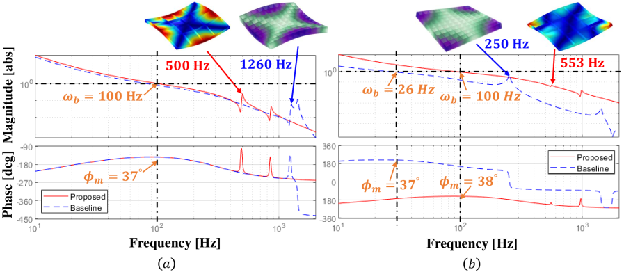
Table. II summarizes the performance of the proposed lightweight stage in case study #1 and that of the baseline stage, and Fig. 8 shows the loop gains of both proposed and baseline designs in the -DOF (translation in the vertical direction) and the -DOF (pitch direction). Comparing the loop frequency responses shown in Fig. 8a, it can be observed both stages can reach a high control bandwidth of with sufficient stability margins in the -DOF, and the Hz resonance in the baseline stage is not shown in its -DOF frequency response. This is because the baseline’s first flexible mode is not controllable or not excitable by the -axis control loop, and thus this resonance does not limit the stage’s control bandwidth in this axis. However, the Hz resonance of the baseline stage can couple in the stage’s -axis dynamics under imperfect actuator or position placement, and stability issue can arise in the control under such situations. In addition, the lightly-damped resonance at Hz in the baseline stage is not actively controlled and thus can be easily excited by disturbances, which can impair the stage’s positioning accuracy.
Comparing the loop frequency responses shown in Fig. 8b, it can be observed that the bandwidth of the baseline stage is only 26 Hz. This is primarily due to the 250 Hz resonance peak in the stage dynamics is coupled into the stage’s control in the direction with the current actuator/sensor configuration, and thus limits the achievable control bandwidth. In contrast, the proposed design can robustly achieve a control bandwidth of 100 Hz since the stage’s first resonance mode at 50Hz is actively controlled.
Finally, comparing the performance shown in Table II, it can be seen that the weight of the proposed stage design is reduced by 85% compared to baseline design. To our understanding, this significant gain in weight reduction is due to the proposed stage is allowing compliance in the first flexible mode, which effectively removes material in the stage structure needed to reinforce the stage. This result shows the tremendous potential of the proposed approach in stage acceleration improvement and the power consumption reduction. In addition, comparing the closed-loop damping performance of the stage’s first resonance mode, it can be seen that the baseline stage’s resonance at Hz is only having a low damping ratio of 0.01, which can be excited by external disturbances. In contrast, the first flexible mode of the proposed stage is under closed-loop control, which has a bandwidth of Hz and has a closed-loop damping ratio of . This improvement in the structural damping shows the potential of the proposed approach to improve the stage’s positioning accuracy under external disturbances.
IV-B Case study #2
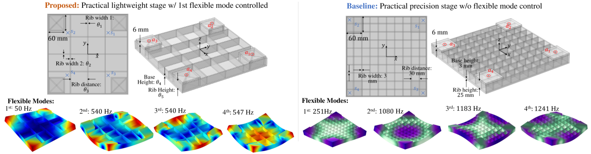
Case study #2 considers a magnetically-levitated planar motion stage as illustrated in Fig. 10, where four neodymium permanent magnet arrays of are arranged at the corner of the stage to provide both thrust forces for planar motion and the levitation forces. The inclusion of the actuator magnets enhances the practical relevance of the case study for wafer positioning application. The vertical-directional levitation forces are assumed to be located at the center of the permanent magnet arrays. All other stage geometry parameters are defined in the same way with case study #1.
As stated in Remark III.1, the value of sets an upper bound for the achievable control bandwidth for the proposed positioning stage. However, using a high value of can enforce the stage design to increase materials to stiffen the corresponding resonance mode, and thus increase the stage’s weight. Therefore, to fully explore the feasible designs set as illustrated in Fig. 2 and thus to remove possible design conservatism, the value of needs to be swept. It is worth pointing out that the stage geometry design (2) and the actuator/sensor placement design (3)-(4) collaboratively determine the plant dynamics of the positioning stage. When conducting a parameter sweep for , the actuator/sensor placement problems must also be solved for each stage geometry design for effective design optimization.
To reduce possible design conservatism and thus fully exploit the advantages brought by the flexible mode control, the feasible stage design set for case study #2 is explored as follows: First, a target control bandwidth is selected to be Hz for the positioning stage. Next, the stage geometry optimization problem (2) is solved with , i.e. of the target bandwidth. Then, the sensor positioning optimization problem (4) is solved with . Note that the actuator’s locations are fixed due to the inclusion of magnet arrays. With one feasible stage and sensor positioning design provided by the previous steps, we then decrease the value of by a constant step and resolve (2) and (4). Assuming is sufficiently small, the change in optimal geometric parameters can be assumed continuous, which allows us to use the optimal solution from the previous run as the initial parameters when resolving (2). This method effectively reduces the required computation time. The previous steps are repeated until is sufficiently low such that it may be excited by external disturbances. In this case study, the lowest value of is selected to be at 300 Hz.
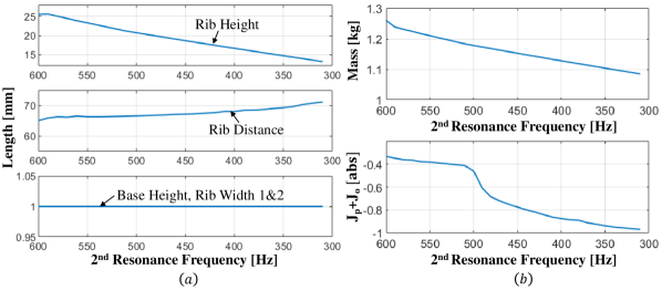
In the stage geometry optimization problem, the optimal solutions always have the stage’s second resonance frequency match . Fig. 11 shows the stage geometric parameters and the resultant stage weight and actuator/sensor placement objectives under varying . It can be observed that the stage’s weight is reducing as the value of decreases, and the value of (i.e. sum of objectives of (3)-(4)) is also decreasing along with the reduction of . These observations reveal new trade-off between the stage’s achievable control bandwidth and acceleration (assuming constant thrust force generation), which is illustrated by the orange line in Fig 2.
The stage hardware design can be manually made among the optimal designs based on the results shown in Fig. 11. In this case study, is selected to provide sufficiently high values while reducing the stage’s weight. Compared to the initial stage design using , the stage’s weight is reduced by 4.5%. Although the improvement is not significant, it is worth pointing out that the geometry optimization of the stage is relatively limited in the current formulation with only five parameters that can be varied. A more significant improvement in the stage’s performance may be expected given increased design flexibility is allowed in the stage structure. The resultant stage’s flexible modes are illustrated in the bottom left in Fig. 10. The state-space dynamic model of the stage can be derived for this stage in the same way as discussed in case study #1, and controllers are designed for the decoupled motions.
To evaluate the effectiveness of our proposed framework considering actuator weight and constraints, a baseline lightweight stage with same magnet array is simulated for comparison. In the baseline stage, only the rigid-body motions are under active control, and all flexible modes are uncontrolled. With a target bandwidth of 50 Hz, the stage’s geometric parameters are designed to constrain the first resonance frequency above 250 Hz. Fig. 10 show the baseline stage design parameters and actuator/sensor location. Three SISO controllers as (6) are designed for all decoupled DOFs in the same way with case study #1.
| Baseline Design | Proposed Design | |
|---|---|---|
| Stage weight | 2.67 kg | 1.20 kg |
| First res. freq. | 251 Hz | 50 Hz |
| 2nd res. freq. | 1080 Hz | 540 Hz |
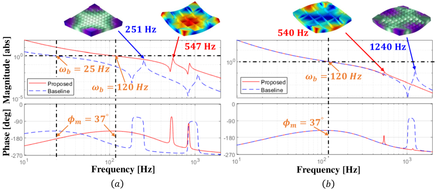
| motion bandwidth | 25 Hz | 120 Hz |
| bandwidth | 120 Hz | 120 Hz |
| Max sensitivity | 1.80 | 1.94 |
Table. III summarizes the performance and comparison of the proposed and baseline stage design in case #2, Fig. 10 illustrates the loop gains of both proposed and baseline designs in - and -DOFs. Comparing the loop frequency responses in Fig. 10a, it can be observed that the bandwidth of the baseline design is limited to 25 Hz due to the Hz resonance peak. In contrast, the proposed design can reach a bandwidth of 120 Hz with sufficient stability margin. Fig. 10b shows that both designs can reach a bandwidth of 120 Hz in the -DOF. This is because the Hz resonance peak in the baseline stage is not excitable by the feedback loop. However, similar to the -DOF in case study #1, stability issue can be caused if the actuator/sensor placement is imperfect. Moreover, the lightly-damped Hz resonance mode can be easily excited by external disturbance and thus impair the stage’s positioning precision.
Finally, Table III shows that the weight of the proposed stage design is reduced by 55% compared to baseline design. The significant improvement for a stage considering the weight of magnet array shows the effectiveness and generality of our proposed approach. In addition, comparing the closed-loop damping performance of stage’s first resonance mode, it can be stated that the proposed design is more robust against external disturbances with the first lightly-damped mode at 547 Hz, while that of the baseline stage is at Hz. The comparison indicates the huge potential of our framework to improve both the stage’s acceleration capability and positioning accuracy simultaneously.
V Conclusion and future work
In this work, we proposed and evaluated a sequential hardware and controller co-design framework for lightweight precision stages, aiming at enabling designs that can achieve high control bandwidth and high acceleration simultaneously. The algorithm of the framework is presented, and the effectiveness of the proposed method is demonstrated by numerical simulations using two case studies. The significant weight reduction (55%) and improvement in control bandwidth show the potential. Future work will consider the experimental evaluations for the proposed method. A fully integrated controller and hardware co-optimization that can better exploit the synergy between hardware and control designs will also be studied.
References
- [1] J. Albero, S. Bargiel, N. Passilly, P. Dannberg, M. Stumpf, U. Zeitner, C. Rousselot, K. Gastinger, and C. Gorecki, “Micromachined array-type mirau interferometer for parallel inspection of mems,” Journal of Micromechanics and Microengineering, vol. 21, no. 6, p. 065005, 2011.
- [2] H. Butler, “Position control in lithographic equipment [applications of control],” IEEE Control Sys. Mag., vol. 31, no. 5, pp. 28–47, 2011.
- [3] A. Delissen, D. Laro, H. Kleijnen, F. van Keulen, and M. Langelaar, “High-precision motion system design by topology optimization considering additive manufacturing,” in 20th Int. Conf. of the European Society for Precision Eng. and Nanotech., EUSPEN 2020. EUSPEN, 2020, pp. 257–258.
- [4] R. Ding, C. Ding, Y. Xu, W. Liu, and X. Yang, “An optimal actuator placement method for direct-drive stages to maximize control bandwidth,” in IECON 2020 The 46th Annual Conference of the IEEE Industrial Electronics Society. IEEE, 2020, pp. 556–561.
- [5] G. F. Franklin, J. D. Powell, A. Emami-Naeini, and J. D. Powell, Feedback control of dynamic systems. Prentice hall Upper Saddle River, 2002, vol. 4.
- [6] M. Garcia-Sanz, “Control co-design: an engineering game changer,” Advanced Control for Appl.: Eng. and Ind. Sys., vol. 1, no. 1, p. e18, 2019.
- [7] D. A. Laro, R. Boshuisen, and J. van Eijk, “Design and control of over-actuated lightweight 450 mm wafer chuck,” in 2010 ASPE Spring Topical meeting, Cambridge, Massachusetts, USA. ASPE, 2010, pp. 141–144.
- [8] T. Oomen, “Advanced motion control for precision mechatronics: Control, identification, and learning of complex systems,” IEEJ Journal of Ind. Appl., vol. 7, no. 2, pp. 127–140, 2018.
- [9] T. Oomen, R. van Herpen, S. Quist, M. van de Wal, O. Bosgra, and M. Steinbuch, “Connecting system identification and robust control for next-generation motion control of a wafer stage,” IEEE Trans. on Ctrl. Sys. Tech., vol. 22, no. 1, pp. 102–118, 2013.
- [10] M. Ortega and F. Rubio, “Systematic design of weighting matrices for the h mixed sensitivity problem,” Journal of Process Control, vol. 14, no. 1, pp. 89–98, 2004.
- [11] M. J. Powell, “A direct search optimization method that models the objective and constraint functions by linear interpolation,” in Adv. in opt. and num. analysis. Springer, 1994, pp. 51–67.
- [12] A. M. Rankers, “Machine dynamics in mechatronic systems: An engineering approach.” 1998.
- [13] G. van der Veen, M. Langelaar, S. van der Meulen, D. Laro, W. Aangenent, and F. van Keulen, “Integrating topology optimization in precision motion system design for optimal closed-loop control performance,” Mechatronics, vol. 47, pp. 1–13, 2017.
- [14] R. van Herpen, T. Oomen, E. Kikken, M. van de Wal, W. Aangenent, and M. Steinbuch, “Exploiting additional actuators and sensors for nano-positioning robust motion control,” Mechatronics, vol. 24, no. 6, pp. 619–631, 2014.
- [15] J. Wu and L. Zhou, “Control co-design of actively controlled lightweight structures for high-acceleration precision motion systems,” in 2022 American Control Conference (ACC), 2022, pp. 5320–5327.