Hawkeye: Hectometer-range Subcentimeter Localization for Large-scale mmWave Backscatter
Abstract
Accurate localization of a large number of objects over a wide area is one of the keys to the pervasive interaction with the Internet of Things. This paper presents Hawkeye, a new mmWave backscatter that, for the first time, offers over (i) hundred-scale simultaneous 3D localization at (ii) subcentimeter accuracy for over an (iii) hectometer distance. Hawkeye generally applies to indoors and outdoors as well as under mobility. Hawkeye tag’s Van Atta Array design with retro-reflectivity in both elevation and azimuth planes offers 3D localization and effectively suppresses the multipath. Hawkeye localization algorithm is a lightweight signal processing compatible with the commodity FMCW radar. It uniquely leverages the interplay between the tag signal and clutter, and leverages the spetral leakage for fine-grained positioning. Prototype evaluations in corridor, lecture room, and soccer field reveal median accuracy at range, and simultaneously localizes 100 tags in only . Hawkeye is reliable under temperature change with significant oscillator frequency offset.
| Systems | Accuracy @ 5 m | Range | Bandwidth | Simultaneous Localization | Fixed Trajectory |
|---|---|---|---|---|---|
| Hawkeye | 2.5 mm | 180 m | 250 MHz | 100 Tags (1024 in theory) | No |
| Millimetro [55] | 78 mm | 180 m | 250 MHz | 6 Tags (106 in theory) | No |
| RFind [33] | 3.4 mm | 6 m | 220 MHz | No | No |
| TurboTrack [32] | 5.1 mm | 10 m | 100 MHz | 2 Tags | No |
| Tagoram [60] | 10 mm | 12 m | 6 MHz | No | Yes |
1 Introduction
Precise interaction with a large number of objects spread over a region has long been a vision for the IoT, where accurate localization is one of the essential features for an immersive experience. Backscatter possess great potential towards this goal, with the low-cost and ultra low-power tags that can be massively deployed over a large area with the minimum deployment cost and maintenance efforts. Localization of large-scale (e.g., hundreds to thousands) tags with subcentimeter accuracy installed over an area (e.g., hectometer-range) would offer benefits to a wide range of applications including asset tracking, inventory management, warehouse automation, smart factories, virtual/augmented reality, and structural health monitoring.

To this end, backscatter (including RFID) localization has been extensively studied in sub-6GHz bands. However, their accuracy, scalability, and range are fundamentally throttled by the hard bandwidth constraint (e.g., tens of KHz for UHF RFID). This limits their performance to tens of accuracy [4, 8, 37, 45, 65], restricts the deployment scenarios by requiring fixed movement trajectories [42, 50, 60, 62], or requires deploying dense reference tags with prior knowledge [5, 13, 58]. A recent line of research, RFind [33] and TurboTrack [32], resolve the bandwidth issue by enabling RFID to emulate the wide bandwidth of 220 MHz that extends beyond the ISM band, to achieve subcentimeter accuracy. However, the range is bounded to several meters to remain compliant to the FCC regulations, limiting the usage to a room-scale and requiring a customized reader. The latest work of millimetro [55] takes a fundamental approach of exploring the rich, 250 MHz bandwidth in the 24 GHz mmWave band, by utilizing FMCW radar and backscatter tag to reach over range. However, the median accuracy of millimetro is limited to , which is essentially the accuracy of 24 GHz FMCW radar.
This paper presents Hawkeye (Figure 1), a mmWave backscatter localization with the empirical performance of (i) median accuracy (ii) at range (@1D), (iii) simultaneously localizes 100 tags in only (scales up to 1024 tags in theory), and (iv) uses an affordable commodity radar (200 USD [17]). Hawkeye blends a new backscatter tag for efficient signal delivery and lightweight radar-side signal processing for accurate and rapid localization. Hawkeye backscatter tag is a planar Van Atta Array (VAA) combined with a power-efficient low-loss FSK modulator using hybrid coupler. The tag retro-reflects in both azimuth ( FoV) and elevation ( FoV) to enable 3D localization and effectively suppresses multipath. The design is robust against oscillator frequency offset, with only 4 localization error across low (), high (), and room () temperatures. This is an essential property for practical subcentimeter localization under disparate deployment scenarios, using low-end tags. Furthermore, one-shot interrogation localizes up to 1024 tags (evaluated with 100) simultaneously, supporting large-scale rapid localization. Table 1 summarizes the comparison to the state-of-the-art backscatter localization systems, showcasing that Hawkeye is uniquely positioned to achieve high scalability, long range, and precision at the same time.
Hawkeye exploits the interplay between Hawkeye back-scatter FSK signal and the chirp-based Frequency Modulated Continuous Wave (FMCW) radar to improve the localization performance by over 60 over using the FMCW alone. Hawkeye tag is tuned to demonstrate S11 of -10 dB throughout the entire 250 MHz bandwidth, where FSK modulation is performed by the combination of reflective network and low-loss hybrid coupler co-optimized for efficient VAA reflection. The use of the VAA, along with the severe signal attenuation of the mmWave, naturally suppresses the multipath inteference. To the best of our knowledge, Hawkeye tag is the first planar VAA mmWave backscatter design with modulation capability. The radar-side subcentimeter localization is designed as a lightweight post-processing on top of FMCW demodulation, without requiring any change to the commodity FMCW radar. Specifically, Hawkeye localization algorithm is built on the recent technique of HD-FMCW [11] that isolates the tag FSK signal from the clutter noise. The key insight of Hawkeye is to leverage the relationship between the tag signal and the clutter, and the spectral leakage signature embedded in the tag signal, from which the precise location can be extracted. Hawkeye supports single radar or multilateration positioning, where 1D-3D localization was evaluated throughout indoors (corridors and lecture rooms), outdoors (soccer field), NLOS, and varying temperatures to demonstrate practicality.
Hawkeye is an accurate, long-range, and large-scale localization for mmWave backscatter, essentially enabling tracking many objects spread over an area, ranging from everyday spaces like homes and offices, to industrial sectors such as inventories and warehouses. Hawkeye is kept economic with low-cost tags and compatibility to affordable commodity radar. To sum up, we believe Hawkeye takes a solid step towards bringing pervasive tag deployment and localization to practice. Our contribution is three-fold:
-
•
We design Hawkeye, a mmWave backscatter-based subcentimeter localization that works over hecto-meter-range and simultaneously localizes over a thousand tags.
-
•
To the best of our knowledge, we design the first planar VAA mmWave backscatter with modulation capability.
- •
-
•
We will release Hawkeye’s source code and HFSS tag design file upon acceptance, for facilitating community’s future works.
2 Background
This section provides the technical background for Hawkeye, followed by the design overview.
FMCW Radar. An FMCW radar leverages chirp, whose frequency linearly increases with time. Objects in the radar’s vicinity reflect the transmitted chirp, which returns to the radar with a round-trip propagation delay. FMCW radar mixes the transmitted chirp with the received chirp (with propagation delay) to produce an IF signal. The range is measured by performing FFT on the IF signal, where each reflected object is represented as a signal with range frequency proportional to the propagation delay.
Planar Van Atta Array. Planar Van Atta array (VAA) passively reflects back the signal to the direction of arrival, achieving retro-reflectivity in both azimuth and elevation planes. It is a simple antenna array structure where centrosymmetric pairs of the antenna in 2D plane are interconnected by transmission lines (TLs) with a length difference equal to (i.e., guided wavelength, which is the wavelength of EM wave in the dielectric).
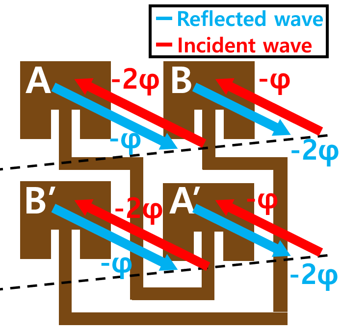
The centrosymmetrically interconnected antenna pair flips the incident signal’s phase sequence, which directs the signal to the source. The phase induced by the TLs does not affect the radiation direction, because it is applied equally to all lines. As an illustrative example in Figure 2, consider a 22 planar VAA, where the signal comes in the azimuth plane with the phase sequence of [, ] at both [A,B] and [B’,A’]. After the propagation in TL, the phase sequence is inverted and produces a reflected signal with a phase sequence of [, ] at both [A,B] and [B’,A’]. This makes the reflected wave back to the incident angle achieving retro-reflectivity in the azimuth plane. Retro-reflectivity in the elevation plane is also achieved in the same manner, by flipping the phase sequence at [A,B’] and [B, A’].

3 Hawkeye Tag Design
Figure 3 presents Hawkeye tag prototype, which uniq-uely blends a 44 planar Van Atta array with FSK modulation which serves as a basis to long-range subcentimeter 3D localization with effective multipath suppression. In the following, we present detailed structure and design choices.
3.1 Retro-reflectivity via Planar VAA
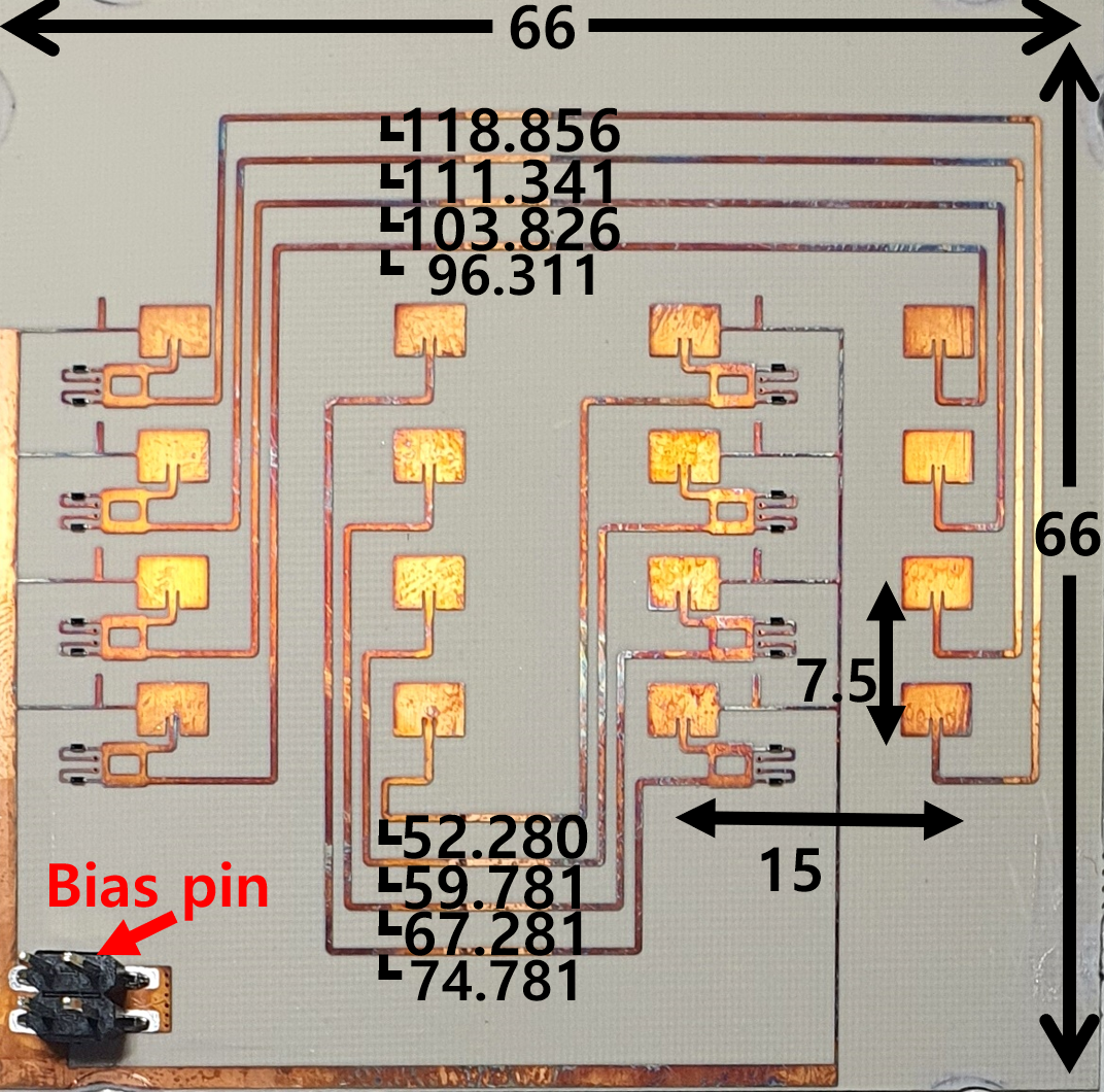
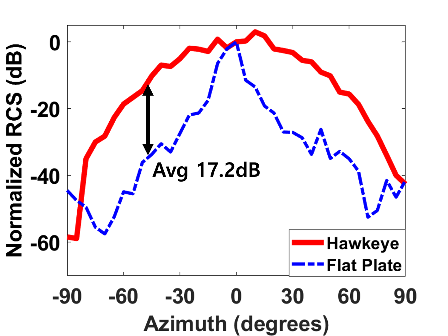
As depicted in Figure 4, Hawkeye VAA achieves retro-reflectivity with an average beamforming gain of dB with FoV (10dB beamwidth) of and in azimuth and elevation, respectively. To meet the VAA condition, centrosymmetric antenna pairs are interconnected via TLs, whose lengths are based on the guided wavelength of , derived from the 24.125 GHz (i.e., the center frequency of 24GHz band). Specifically, the length differences of TLs are multiples of . To limit the phase misalignment within the 250MHz bandwidth, the difference between the maximum and the minimum TL lengths is capped to . This translates to the maximum phase misalignment of , or equivalently, beamforming power loss of only dB.
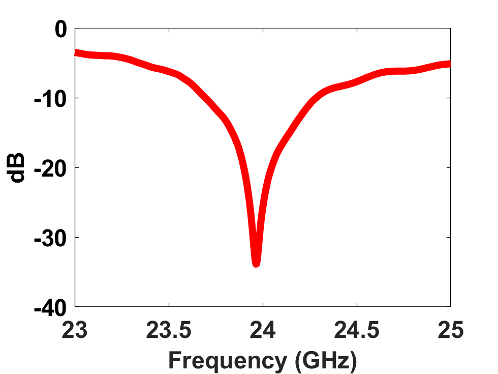

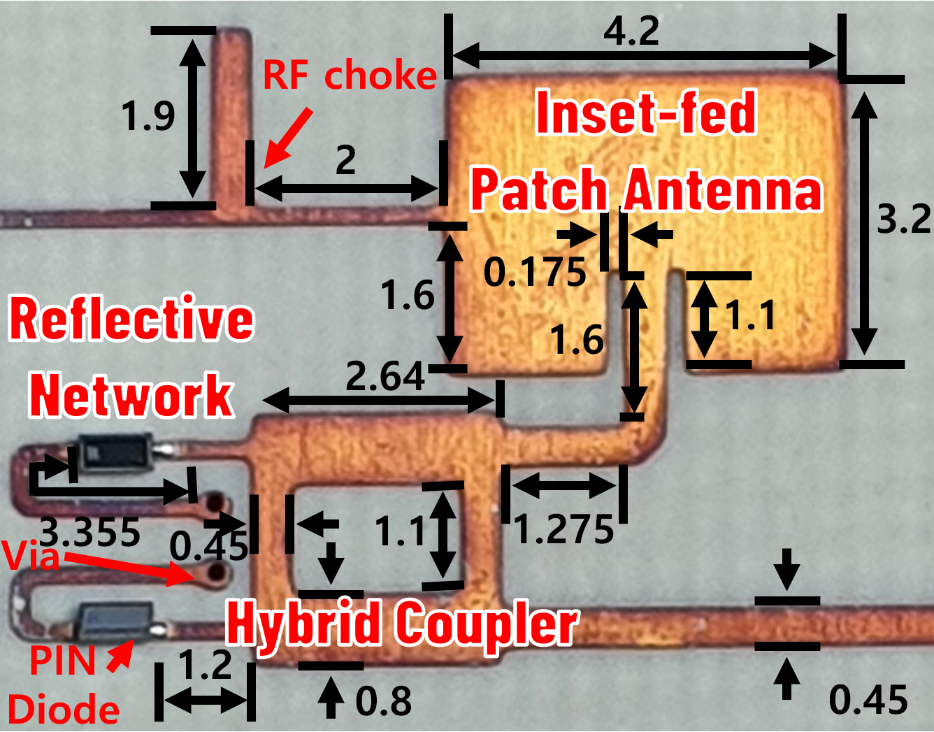
Hawkeye tag adopts inset-fed rectangular microstrip patch antenna with the patch, edge notch depth (i.e., the antenna feeding point [38]), and TL dimensions optimized to 50 impedance matching at 24GHz, through HFSS parametric sweep. Figure 5 demonstrates the antenna performance measured via VNA; Figure 5(a) depicts the antenna response (S11) of dB throughout the 24 GHz band, and Figure 5(b) shows the corresponding impedance matching results. The parameters are shown in Figure 6(a) on Rogers RO4003C substrate (dielectric constant , dissipation factor tan), where the top layer holds Hawkeye tag circuit while bottom layer is ground plate. Lastly, 44 antenna elements are chosen to balance between the FoV of the retro-reflectivity and the tag size – i.e., the maximum beam inclination111Max beam inclination for antenna array is [19], where , , and are # of antenna elements, wavelength, and antenna spacing, respectively. increased beyond 44 becomes marginal, relative to the exponentially increasing size.
3.2 Low-loss Modulator for Planar VAA
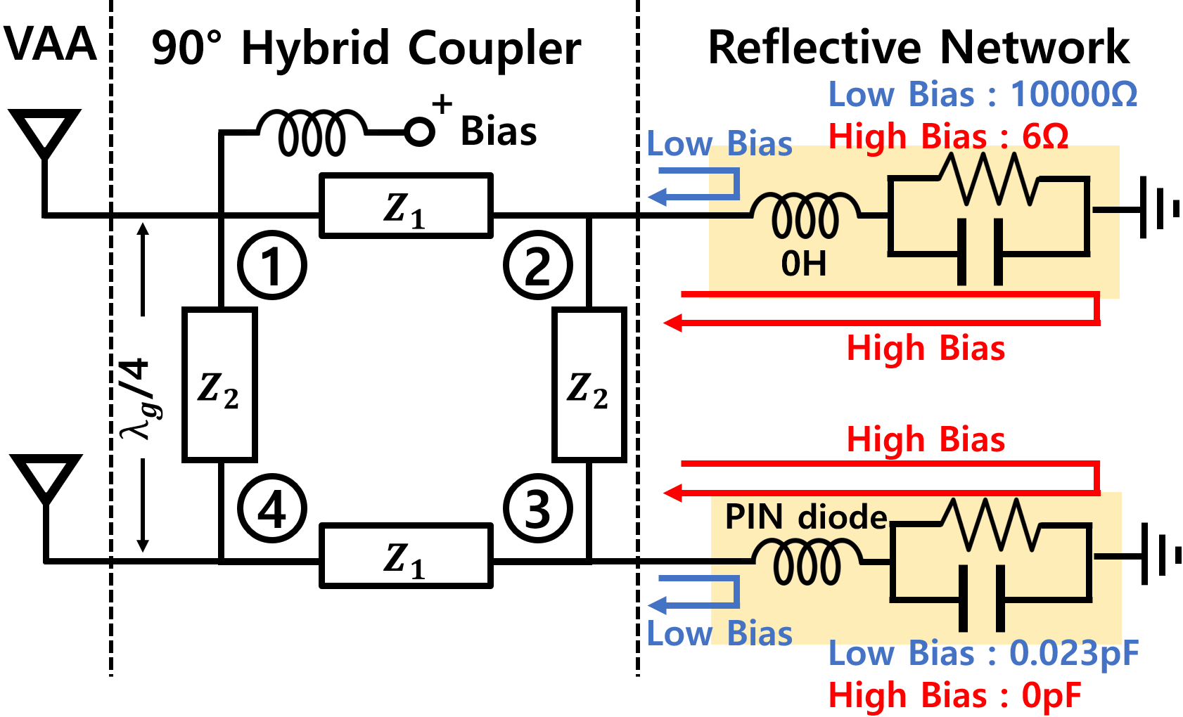
An efficient modulator directly affects the SNR of the tag signal, which determines the tag’s detection robustness. Given Hawkeye operating throughout the 250 MHz bandwidth in the 24 GHz, this section discusses how it effectively performs FSK modulation without affecting the retro-reflectivity. Figure 6(b) presents the equivalent circuit representation of an antenna pair, corresponding to Figure 6(a). Hawkeye tag consists of 8 such antenna pairs, each equipped with a hybrid coupler and a reflective network for FSK modulation via periodic phase shifts. As shown in Figure 6(a), both the coupler and the reflective networks have microstrip architecture with a couple of PIN diodes. This structure enables Hawkeye to maximize SNR by (i) low-loss characteristic of the hybrid coupler in combination with symmetric reflective networks, and (ii) keeping the retro-reflectivity intact whilst FSK modulation via carefully designed bias and compensation of the coupling effects, avoiding leakage or distortion of the signal. Our design collectively brings low-loss FSK modulation, laying a solid foundation for hectometer-range support, in combination with the unique localization algorithm in Section 4.
Low-loss Phase Shifting using Hybrid Coupler. Hawkeye performs energy-efficient FSK via (i) phase shifts with (ii) Hybrid Coupler, minimizing the backscatter reflection loss at the Hawkeye tag. As in Figure 6(b), the phase is flipped depending on the length of the signal path at the reflection network, controlled by the ON (high bias) and OFF (low bias) states of the PIN diode. This retains the incident signal power for low-loss modulation (cf. many state-of-the-art backscatters modulate via SPDT switches, to toggle between absorption and reflection states [11, 39, 55] – essentially sacrificing the half of the interrogation signal power (during absorption)). For retro-reflectivity, the modulated interrogation signal flows into the other side of the antenna pair. This is achieved with low-loss via a hybrid coupler and a reflective network in Figure 6(b), performing as the impedance matched TL (details in the later part of the section). Alternative low-loss modulator is the switched line phase shifter that switches between two TLs with different lengths. However, this design requires diodes than the hybrid coupler [24] to induce higher power consumption and cost. While the switched line phase shifter has advantage in the formfactor, this advantage is insignificant in mmWave.
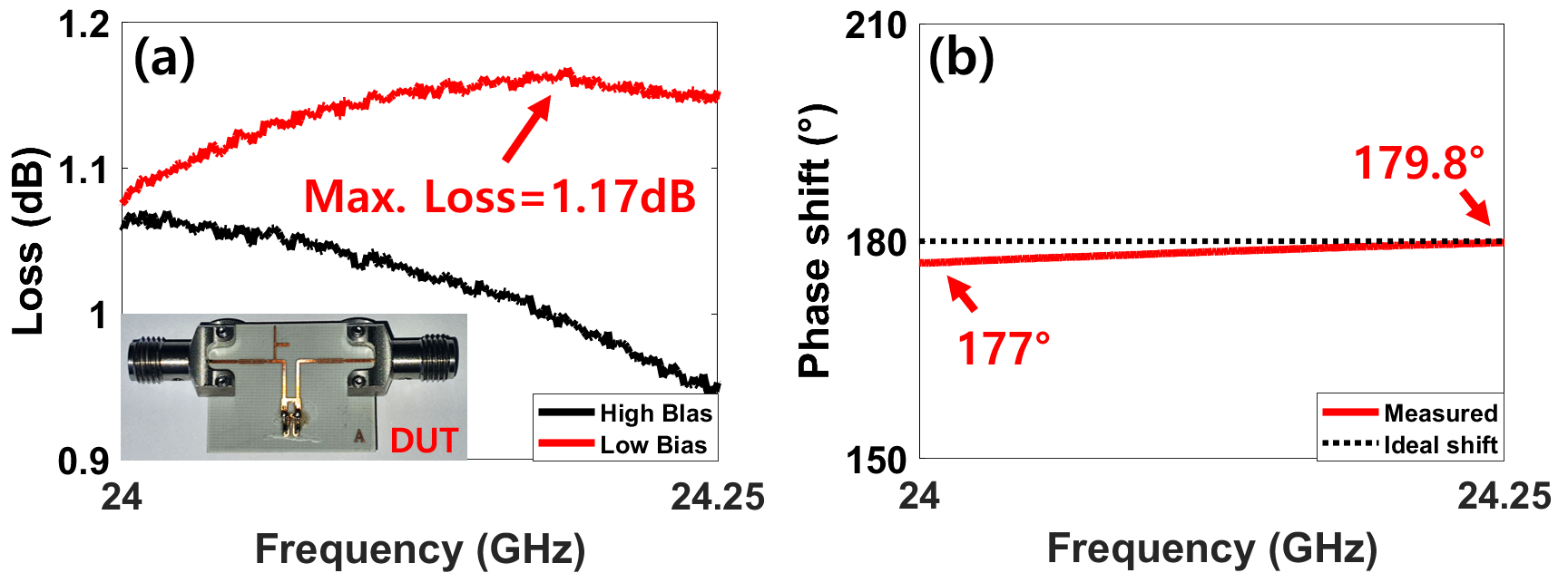
To understand the operation of Hawkeye phase shifter, let us refer to Figure 6(b) where the incident interrogation signal is received at the upper antenna (port \raisebox{-.9pt} {1}⃝) and flows into the lower antenna (port \raisebox{-.9pt} {4}⃝). To maintain the retro-reflectivity alongside FSK modulation, the hybrid coupler performs low-loss signal transfer from the port \raisebox{-.9pt} {1}⃝ to port \raisebox{-.9pt} {4}⃝, with the reflective network in between. For this, the hybrid coupler acts as an impedance-matched TL with low insertion loss [24], by the following operation: The incident signal is divided into four paths by the coupler, each flowing into reflective networks and bouncing off back to the coupler – i.e., : , : , : , and : . Hybrid coupler with four TLs yields 180∘ phase difference between and , and the same phase between and [49]. By keeping the signal amplitudes in the four paths identical, and cancel each other at port \raisebox{-.9pt} {1}⃝. Therefore, no signal is radiated on the upper antenna, thereby minimizing the reflection (i.e., =0). On the other hand, and are constructively added at port \raisebox{-.9pt} {4}⃝ for maximized radiation on the lower antenna (i.e., ). In summary, the incident signal is maximally delivered from the upper to the lower antenna, or equivalently, the insertion loss is minimized when the signal amplitudes in the four paths are the same. The path amplitude ratios are computed as and when [49]. For the ratios of 1, we get and , that is, 35.3 and 50, respectively. VNA measurement in Figure 7(a) shows the low-loss of under 1.17 dB, where the modulator was isolated from the tag (DUT in the figure) for precise measurement.
Incorporating the Modulator and Planar VAA. For precise phase shifts throughout the entire 250 MHz in the 24 GHz we leverage an equivalent circuit in Figure 6(b) with the PIN diode MADP-000907-14020 represented in corresponding R, L, and C as per the datash-eet [35]. Also, to maintain VAA retro-reflectivity while combining with the FSK modulator, RF leakage through the bias line (driving the PIN diodes) should be avoided – the leakage would distort the phase and corrupt the retro-reflectivity. Hawkeye adopts open stub (i.e., an open-ended microstrip line [15]) as an RF choke to prevent RF leakage, which is represented as an inductor in the equivalent circuit. The parameter values are found through an extensive HFSS parameter sweep simulation, including the TL lengths and gaps between TLs to compensate for the coupling effect between the modulator and the TLs. The parameter values are shown in Figures 3 and 6(a). As in Figure 7(b), Hawkeye modulator yields an accurate FSK with the maximum error of 3∘ (i.e., [177∘, 179.8∘]), indicating only dB power loss throughout the entire 250 MHz in the 24 GHz band. The RF signal was effectively isolated by greater than 30dB by the RF choke to achieve FSK modulated retro-reflectivity.
3.3 Indoor Multipath Suppression
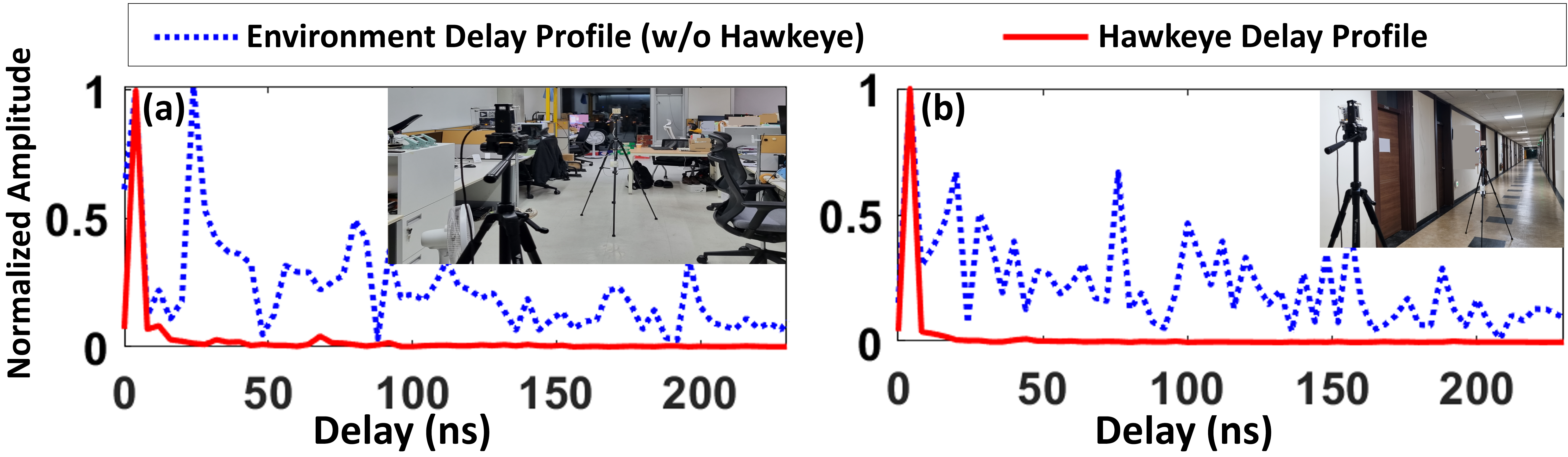
Retro-reflectivity of Hawkeye effectively suppresses the multipath, enabling robust indoor localization. Figure 8 presents the delay profile measured from two multipath-rich indoor settings of an office and a hallway. In both scenarios Hawkeye significantly reduces the delay spread and limits the multipath signal power to be 20dB or more below the LOS signal. This is because, under retro-reflectivity, the received NLOS (i.e., multipaths) signals are strictly limited to the direction to which the signals are sent (instead of all directions without retro-reflectivity). Thus, higher the retro-reflectivity, less the delay spread. The multipath suppressed by Hawkeye tag in Figure 8 induces only (office) and (hallway) error in Hawkeye localization (Section 4), enabling subcentimeter indoor positioning as demonstrated in Section 5.3.

4 Hawkeye Localization
In this section, we describe how Hawkeye achieves subcentimeter localization at hectometer-range, using the commodity radar and Hawkeye tag. Essentially, it is an extremely accurate ranging design that can be extended to 2D/3D localization with mutliple (multilateration) or single radar. At a high level, Hawkeye leverages the spectral leakage signature of a tag signal to extract super-resolution range frequency. Our design leverages a recent technique of HD-FMCW presented in OmniScatter [11]. We first provide a brief primer on HD-FMCW, followed by the subcentimeter localization supporting mobile tags and large-scale simultaneous localization.
HD-FMCW Primer. A recent technique of HD-FMCW, with a light add on signal processing on commodity FMCW radars, effectively isolates the FSK signal from the clutter noise in the frequency domain. Compared to the original FMCW which uses a single-chirp symbol, HD-FMCW leverages multiple (periodic) chirp symbol, , where is a chirp with duration , is the number of chirp repetitions, and is the convolution. This interrogation signal, when reflected from the clutter (i.e., clutter noise), simply becomes where is the round trip propagation delay between the radar and the clutter. Since it is simply a time-shifted version of the interrogation signal, it maintains the period of . This is therefore represented as peaks on the multiples of frequency bins in the IF signal, where all other bins in between are left zero222From the Fourier’s Theorem [7], an arbitrary signal with period seconds in the time domain is represented as the multiples of in the frequency domain.. Note that, this applies to clutter noise from all sources – i.e., all noises are concentrated on the same set of frequency bins, leaving other bins zero. On the contrary, the interrogation signal reflected off the tag (i.e., the tag signal) is not only time-shifted, but also modulated by the tag FSK. Specifically, the tag signal is
| (1) |
where is the modulation frequency of the FSK. This yields a new period, other than (i.e., the least common multiple of and ). Therefore, in IF, tag signal and clutter noise are placed in different frequency bins – isolating the tag signal from all environmental clutter noise. The separation of tag and clutter is demonstrated at Figure 9, where HD-FMCW (Figure 9(b)) isolates the tag signal unlike the original FMCW (Figure 9(a)).
4.1 Subcentimeter-accuracy Localization
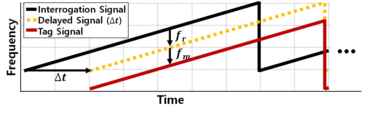
Hawkeye localization uniquely leverages the relationship between the isolated tag signal and the clutter noise in the HD-FMCW, and the spectral leakage signature embedded in the tag signal. Figure 11 illustrates the reflected tag signal in relation to the interrogation signal, where the offset between the two signals is the combination of and . The range frequency is from the tag-radar propagation delay whereas is the FSK modulation frequency. In other words, indicates the true position of the tag and therefore, accurate localization translates to the problem of finding . This is achieved in two steps: (i) Removing the effect of from the relationship between the tag signal and clutter noise, and (ii) precise estimation of from the spectral leakage signature, which we discuss in the following.
Eliminating Tag Modulation . The first step to achieving accurate estimate of the range frequency is to eliminate the effect of in the IF signal. We note that, in practice, is not known in advance; It needs to be detected in real time due to the instability of the oscillator speed. For instance, a crystal oscillator can have variance under different environments [40]. This indicates error at , which can translate to a vast amount of over localization error. Hawkeye is inherently robust to the oscillator variance, as it detects the accurate on the fly, without any prior knowledge on the modulation speeds or the environment under which the tags are installed.
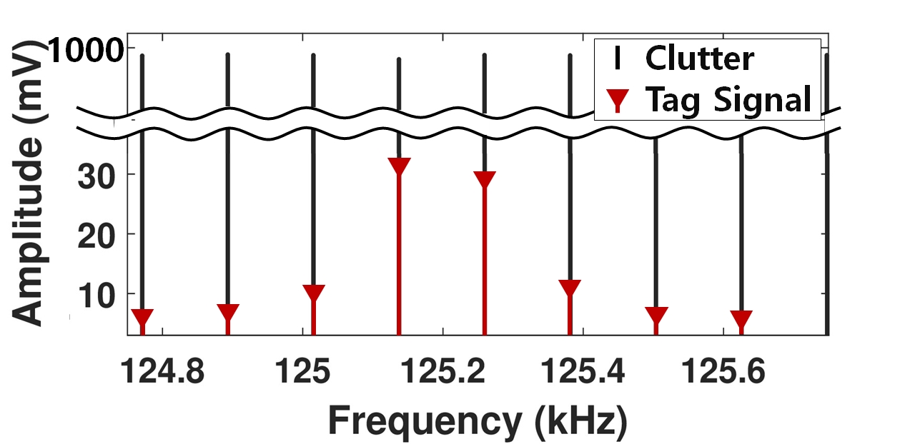
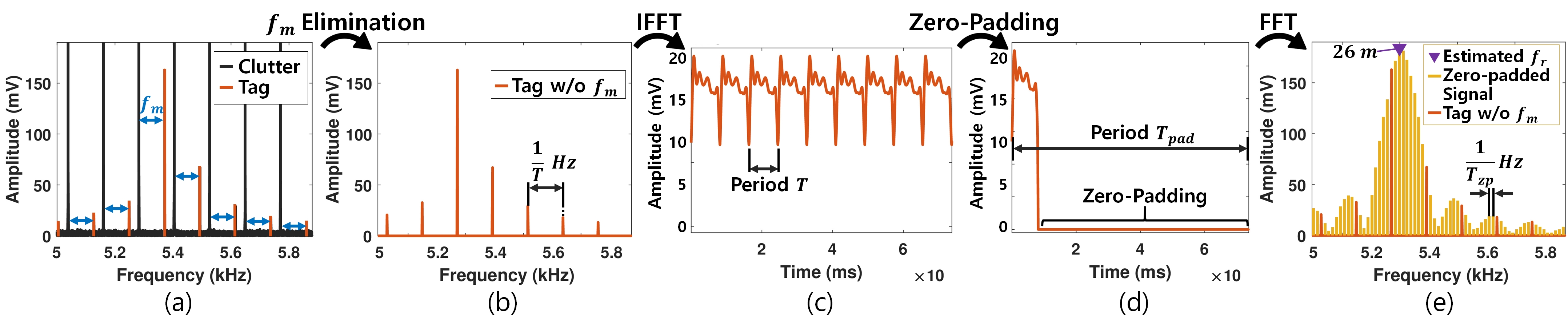
In order to precisely identify , we begin from the fact that originates from the propagation delay between the radar and tag, or equivalently, ( Eq. 1) that has the period . On the contrary, stems from the FSK signal of with period . As a result, the IF signal is represented as peaks at frequencies with Hz interval (from ), with offset of (from ) as depicted in Figure 10(a). Thus, the can be precisely determined in real time, simply from the offset from frequency bins. We note that those frequency bins hold the clutter noise; Therefore, to remove , the clutter noise are first nullified to zero, and then the tag signal is shifted to the nullified frequency bins. Figure 10(b) depicts the resulting clean signal with only , free of contamination from and clutter noise. This is a key technique for subcentimeter localization unaffected from the tag clock offset prevalent in practice.
Extracting Super-resolution Range Frequency . Hawkeye subcentimeter localization is achieved by accurately identifying the (indicating tag-radar distance) with boosted frequency resolution. This deviates from the conventional HD-FMCW, where the is represented with frequency resolution of – i.e., identical to the original FMCW frequency resolution. To do so, Hawkeye exploits the spectral leakage in the discrete Fourier Transform (DFT), where the DFT of a signal with the period of and frequency of is represented as peaks at the multiples of whose envelope follows the sinc function centered at – i.e., [46]. Therefore, accurately deriving becomes the problem of fine-grained identification of the envelope sinc function from which the center frequency can be pinpointed. To achieve this, Hawkeye zero-pads a subset with duration to increase the period to () in the time domain, as depicted in Figures 10(c),(d). Figure 10(e) demonstrates the zero-padding result, where the peaks in the frequency domain are densified to precisely reveal the envelope sinc function. In our experiment we set to keep the computation overhead low while achieving the subcentimeter localization accuracy. Given the dense peaks, the center frequency is simply found as the frequency with the maximum peak amplitude.
An extensive experiment reveals Hawkeye median range error of , over 60 improvement compared to the original FMCW with median error. With the super-resolution acquisition mechanism, Hawkeye achieves subcentimeter localization up to outdoors, and indoors. We note that entire Hawkeye localization algorithm has the computation complexity of (for FFT/IFFT) where is the number of samples – retaining the complexity of the original FMCW that mandatorily runs FFT.
4.2 Mobile Tags
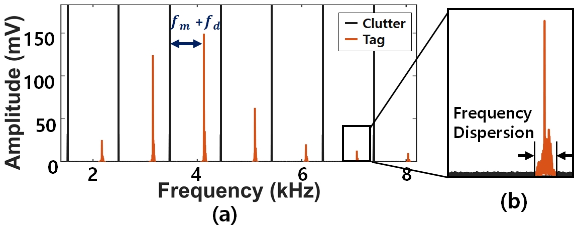
On the contrary to the static tags, a mobile tag induces Doppler frequency and time-varying range frequency . Figure 12(a) illustrates the IF of the mobile tag ( Figure 10(a) for static tag), where is added on top of . The is effortlessly removed together with by simply following the elimination mechanism discussed in the previous section. On the other hand, time-varying range frequency, , causes frequency dispersion of the peak as shown in Figure 12(b). Hawkeye tracks with subcentimeter accuracy, through fine-grained temporal analysis. For mobile localization, we begin by distinguishing the moving tags from the static ones via frequency dispersion, proportional to the tag velocity333This is known as the dispersion factor [22] in radar context. For subcentimeter localization, we define mobile tags as those with movement within a symbol, revealed to be the frequency dispersion of according to our empirical study. Then, the movement is tracked by the following.
Extracting Time-varying Range Frequency . Localization of mobile tags essentially follows the same design principles as Section 4.1, where mobile tag signal is eliminated to run IFFT (Figures 10(a)-(c)), reconstructing the range frequency in the time domain (i.e., ). Subsequently, each subset with duration of can be zero-padded to reveal the precise location at the corresponding time (Figures 10(d),(e)). Hawkeye mobile localization can be configured for balance between time granularity and computation overhead, by choosing the location update interval. For instance, zero-padding can be applied on with a interval to provide localization updates per second (under ). Our evaluations show median error for a humanoid robot with speed, providing evidence for mobile tag localization Hawkeye. We note that the minor modification of Hawkeye sustains computation complexity for mobile localization.
4.3 Large-scale One-shot Localization
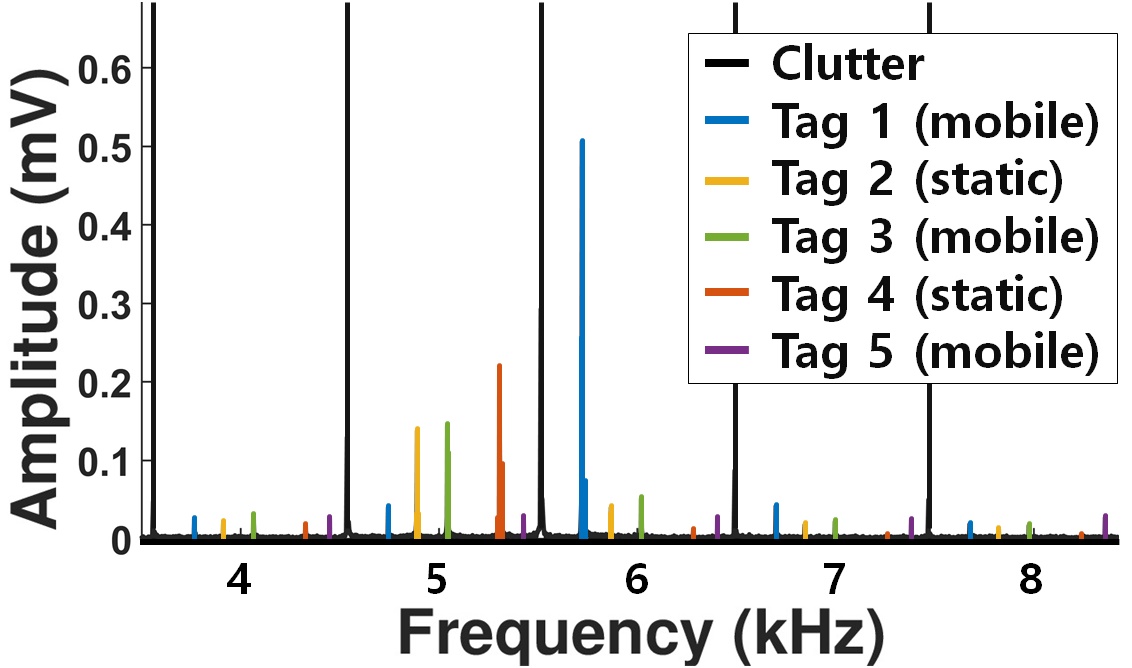
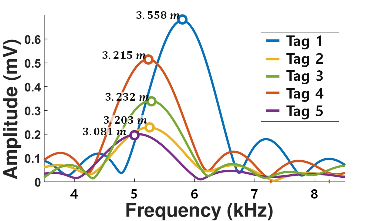
The lightweight localization of Hawkeye can be directly extended to large-scale, for simultaneous localization of mobile and static Hawkeye tags with a single interrogation. For instance, localizing 100 tags takes less than end-to-end ( interrogation + processing time) on a mediocre desktop PC (i7-8700, RAM). We verify simultaneous localization of 100 tags in Section 5.6, where each tag is identified according to its unique modulating frequencies. The localization runs iteratively for each tag, to eliminate tag modulation before extracting accurate range frequency. Figure 13(a) illustrates simultaneous localization of 5 mobile and static tags, where the tags with 200, 500, 890 Hz modulation are mobile and 350, 770 Hz modulation are static. Figure 13(b) depicts successful localization of each tag, where individual tag signals are distinguished according to the modulation frequency. We note that Hawkeye supports up to 1024 tags under interrogation signal ( and ), which translates to interval between each tag IDs. The ample ID space tolerates over frequency offset in low-end crystal oscillators, demonstrating the scalability of Hawkeye in practice. The large scalability, in combination with long-range localization and retro-reflective tag, offers a wide-area coverage.
4.4 Radar Setup
Multilateration. Hawkeye is capable of supporting seamless 2D/3D tag localization, where multiple Hawkeye radars concurrently interrogate Hawkeye tags for multilateration. Essentially, concurrent interrogation is made possible by Hawkeye plannar VAA tag which retro-reflects interrogation signal back to the source radar, efficiently avoiding tag signal interference amongst radars. Hence, Hawkeye radars can be set up for multilateration without the need for access control. Furthermore, Hawkeye radars can be time-synchronized to support 2D/3D localization for mobile tags, utilizing the Network Time Protocol [43]. The protocol provides sub-millisecond accuracy in local area networks, where a millisecond error translates to localization error for a typical human running speed of , sustaining subcentimeter accuracy.
Single Radar Localization. Single radar 2D/3D localization can be achieved by utilizing the AoA of the MIMO radar. Compared to multilateration, single radar localization trades off accuracy for lower deployment cost (less number of radars). Localization error from the AoA inaccuracy is amplified over distance. For instance, an AoA error of causes localization error at (). Single radar localization is demonstrated in Section 5.4.

5 Evaluation
This section presents the implementation details and evaluation results of Hawkeye.
5.1 Implementation
Hawkeye radar is implemented on Eval-TinyRad (Analog Devices) [1] commodity 24GHz radar, where the operation of Hawkeye localization is verified. The radars provide the IF data to PC, where it is collected to perform Hawkeye localization. To deliver the control signal to Hawkeye tag, a fabricated control board with VCXO (i.e., Voltage Controlled Crystal Oscillator) is used with a small form factor of , as depicted in Figure 14. The board uses Skyworks 515NDAM 134200BAG [53] oscillator for an accurate generation with variance. To control the frequency of the VCXO, a variable resistor is combined with a coin cell battery, where a LDO voltage regulator (Toshiba TAR5SB33 [56]) is utilized to stabilize the voltage. Arduino Uno is also implemented as a control board for large-scale localization, where it provides a wider range of ( bandwidth, ) compared to the VCXO ( bandwidth, ).
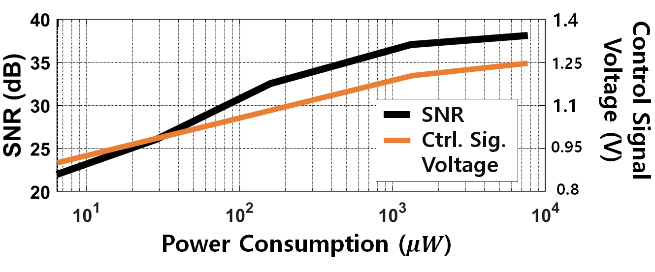
Tag Power Consumption. Hawkeye tag is composed of 16 PIN diodes (Macom MADP-000907-14020), with a separated control board for operation. The tag power consumption is highly variant according to the control signal voltage, as the diodes consume more power at higher control voltage. Figure 15 provides our evaluation on the power consumption vs. SNR at tag-radar distance with interrogation signal. The power consumption is calculated utilizing the diode IV data [34]. The results demonstrate the control signal voltage of (i.e., tag operating at power) is sufficient for the operation of Hawkeye tag at distance with over SNR. Meanwhile, the control board power consumption is analyzed by simulating an IC using the Libero SoC SmartPower [41]. The simulation consists of a ring oscillator and a modulator circuit, where the power consumption results in . Thus, Hawkeye tag can run with power, which can be easily operated by energy harvesting [63], or with a coin cell battery of 1000 for 40.7 years.

5.2 Evaluation settings
By default, we conduct evaluations using Analog Devices Eval-Tinyrad as Hawkeye radar, with the specific radar parameters set as follows: bandwidth 250 MHz (24 GHz to 24.25 GHz), transmit power , IF sampling frequency 1 MHz, and 8192 samples per chirp with 2048 chirps for interrogation signal. We use a single transmit antenna and a single receive antenna for omni-directional Hawkeye operation, unless otherwise mentioned. We note that the PCB fabrication and soldering error may result in separate distance offset per tag, which we calibrate by measuring the distance offset of a tag with known distance. In all evaluations, Hawkeye tag is mounted on a acrylic plate to avoid unnecessary electric coupling. The Arduino Uno is utilized for our control board, which supplies control voltage to Hawkeye tag.
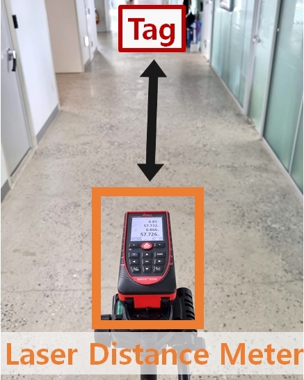
Ground Truth. In order to obtain precise ground truth of localization, laser distance meter with resolution up to 200 meters range (Leica DISTO D510 [27]) is utilized at radar side, as depicted in Figure 16. The tag-radar distance is first measured on the laser distance meter mounted on a tripod, where subsequently Hawkeye radar is mounted on the same tripod for evaluation. At tag side, a linear stage of resolution up to range (Soar STMX1020-D [54]) is utilized as shown in Figure 14. Hawkeye tag is mounted on the linear stage, where the linear stage relocates the tag for evaluation. The ground truth error caused by the laser distance meter does not exceed . For mobile tag evaluation, we utilize OptiTrack PrimeX [47] with 3D accuracy for ground truth.
5.3 1D Localization
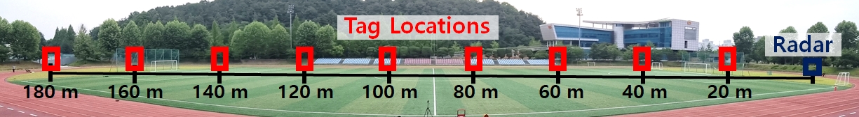
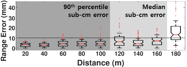
To verify Hawkeye’s subcentimeter accuracy at hectometer range, a 1D localization experiment is conducted at a soccer field, where the measurement is conducted up to 180 meters in a straight line. Hawkeye tag is located at every 20 meters as shown in Figure 17(a), where a total of 100 experimental trials are performed at 20 different locations within each position. Figure 17(b) demonstrates Hawkeye 1D localization performance, where the edge of the box indicates the and percentile error, while the whiskers indicate the and percentile error. Data outside the and percentile error is considered as outliers, which are marked as red dots outside the whiskers. Hawkeye achieves subcentimeter accuracy with percentile error up to , where the error is . Furthermore, the subcentimeter accuracy is sustained up to with percentile (i.e., median) error, where the median error is at , demonstrating successful hectometer range subcentimeter localization. For control signal, Arduino Uno produces . Figure 17(c) shows the detection rate of Hawkeye, where we achieve detection rate up to , which is decreased to and at and . The subcentimeter accuracy at hectometer range proves the robustness of Hawkeye tag, in combination with the efficiency of Hawkeye localization.

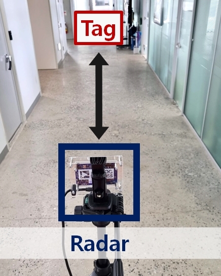
Indoor 1D Localization. We further evaluate 1D localization at multipath rich hallway to verify Hawkeye operation in indoors. As depicted in Figure 18(a), the hallway experiment is conducted up to in a straight line. The tag is located at every , where 50 experimental trials are conducted at 10 different locations within each positions. Figure 18(b) plots the box plot of the indoor 1D localization. The median error stays below throughout 80 meters, validating Hawkeye’s subcentimeter localization even in indoors. The detection rate stayed at up to the range. This results totally prove the multipath suppression of Hawkeye tag.

| LOS | Cardboard | Plywood | |
| Median (mm) | 2.2 | 3.4 | 5.7 |
| percentile (mm) | 5.9 | 5.7 | 11.9 |

Robustness Against Blockage and Temperature Change. Localization for IoT applications may face various environment changes during practical use. In order to substantiate Hawkeye operation for pervasive deployment, we analyze the 1D localization performance impact of two common error sources – blockages and temperature variance. The experiments are conducted in an indoor concert hall, where the tag-radar distance is set to . For each experiment, total 40 experimental trials are conducted at 4 different locations, with Arduino Uno as the control board. Figure 19 shows the setup for the blockage experiments, where cardboard and plywood of and thickness is utilized as blockage materials. The experiment results are summarized at Table 2, where the cardboard and plywood blockage increased the median localization error by and each. The results show that Hawkeye sustains subcentimeter accuracy even under NLOS, demonstrating our robustness to the blockages. Localization performance under varying temperature (i.e., varying due to the instability of oscillator) is also evaluated, to show Hawkeye’s ability to eliminate the effect of for precise localization. As shown in Figure 20, the Arduino oscillator temperature is set to , and , for evaluation. At each temperature, the varied from to , showing high frequency instability of the control board. To control the temperature of the oscillator, the control board was either surrounded by ice pack or hand warmers, as shown in Figures 20(a) and (b). Figure 20(c) compares the localization result with and without Hawkeye elimination. Without the elimination, the error induced by the temperature at and is and each. Contrarily, with Hawkeye’s elimination applied, the error induced by the temperature change at and stays under . Altogether, the results prove the performance of Hawkeye at diverse environments.
5.4 2D Localization
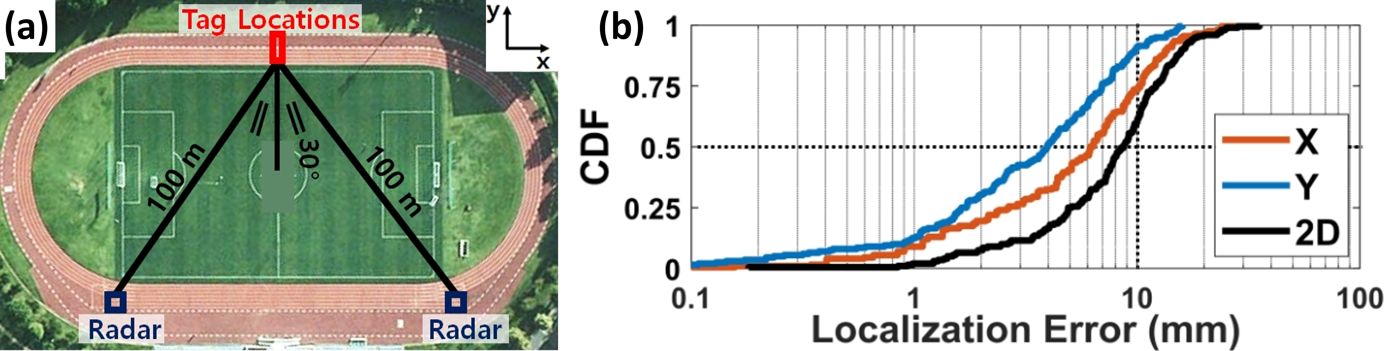
We evaluate hectometer range 2D localization at soccer field with track, utilizing two radars and a single tag for multilateration. As demonstrated at Figure 21(a), the two radars are located at distance from the tag, where the radar interrogates the tag with incidence angle. The distance between the radars is , and the tag modulation is 150 kHz. The experiment consists of total 400 experimental trials, where the tag localization is conducted at 20 positions on the linear stage moving towards positive direction. Figure 21(b) plots the CDF of 2D localization error, where Hawkeye achieves subcentimeter median error of and percentile accuracy of in 2D. Median error along and dimensions are and , while the percentile error is and each. The 2D localization, which inherently requires retro-reflectivity, is made possible by Hawkeye tag’s high retro-reflectivity. The subcentimeter 2D localization at hectometer range demonstrates the capability of Hawkeye at practical applications.
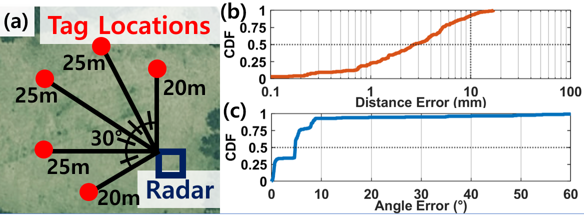
Single Radar 2D Localization. Hawkeye 2D localization on a single radar utilizing AoA is evaluated. The evaluation is conducted at an open field with localization distance ranging from to and AoA ranging from to , as depicted in Figure 22(a). For each location, a total of 30 experimental trials are performed at 6 different locations. Figure 22(b) and (c) show the CDF of distance and angle error, where the median errors are and , and the percentile errors are and . Collectively, the median 2D error results in , whose accuracy can be improved with a larger antenna array.
5.5 3D Localization
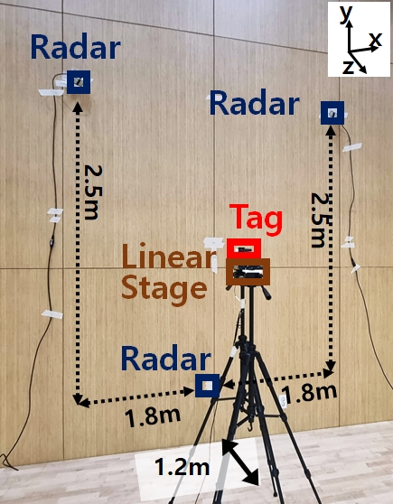
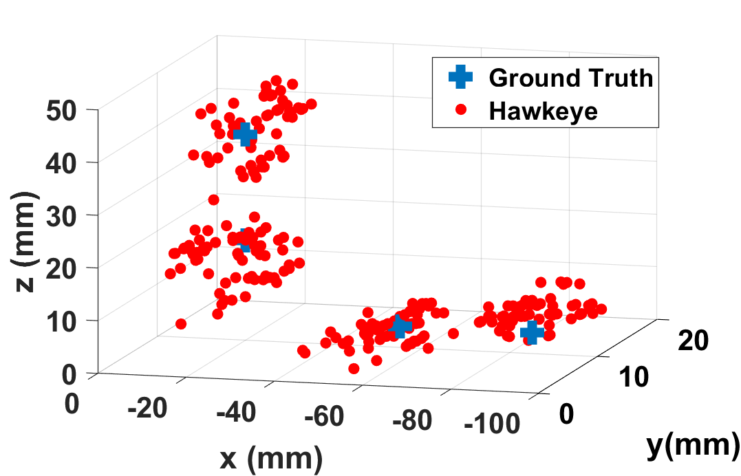
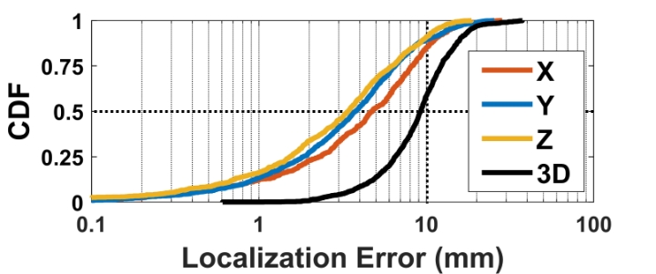
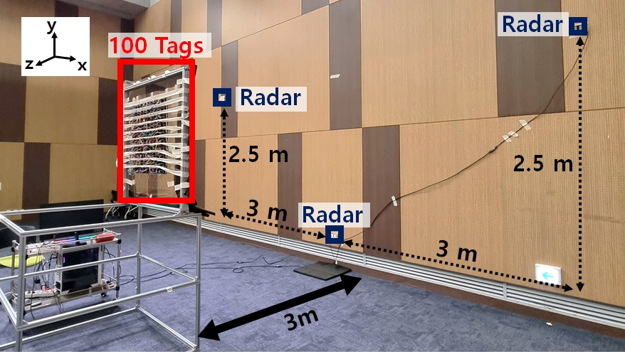
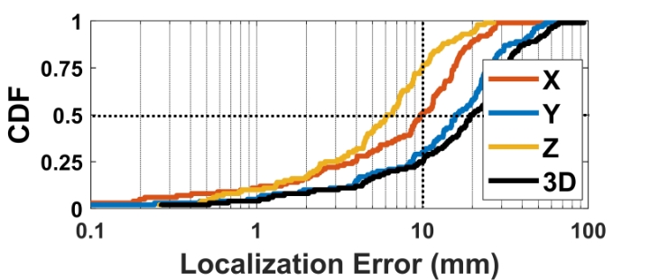
In order to verify the 3D localization performance of Hawkeye, a localization experiment is conducted in an indoor concert hall with three radars fixed to a wall. The radar positions are described in Figure 23(a), where the three radars are located at (1.8, 1.25, -1.2), (1.8, -1.25, -1.2) and (0, -1.25, -1.2) coordinates, assuming is the tag center. Tag control signal of is fed with a signal generator [21] for 3D localization experiment. Total 1840 experimental trials at 23 positions in -plane are conducted utilizing the linear stage. Figure 24 demonstrates the CDF of 3D localization error, presenting subcentimeter median error of and percentile error of . For each dimensions, the median error is , , and percentile error is , , each. Figure 23(b) depicts an exemplary localization result at four tag locations, where estimated points within the median error are plotted in 3D. The successful subcentimeter 3D localization in indoor space proves the retro-reflective performance of Hawkeye tag in both azimuth and elevation plane, while establishing a solid foundation on the practicality of Hawkeye localization.
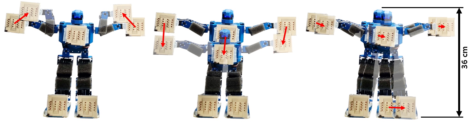

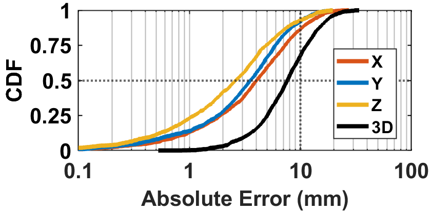
Simultaneous Localization of Mobile Tags. We evaluate Hawkeye’s ability to simultaneously localize mobile tags by attaching five Hawkeye tags to the body center, both legs and both arms of a humanoid robot [14]. Each tag concurrently modulates with unique between 150 kHz and 151 kHz. The experiment is conducted in an indoor concert hall with the same settings as Figure 23(a). The robot has dimension of , operating with 16 servo motors. The radar is set to have 1024 samples per chirp with 2048 chirps for interrogation signal. As depicted in Figure 25, three different actions of lift arms, sit down and spread legs are captured with the maximum moving speed of 17cm/s. A total of 90 experimental trials are conducted per action, with three different robot positions. As depicted, the three robot actions are captured with 23.5 localization FPS, where a ground truth measured by OptiTrack is provided together. The CDF is presented in Figure 26, where the median error of 3D localization is and percentile error is . For each dimension, the median error is , , and percentile error is , , each. This verifies Hawkeye’s one-shot localization of mobile tags in practice.
5.6 Large-scale Localization
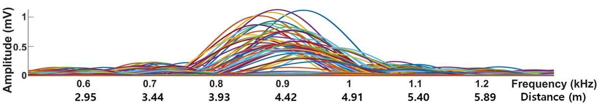
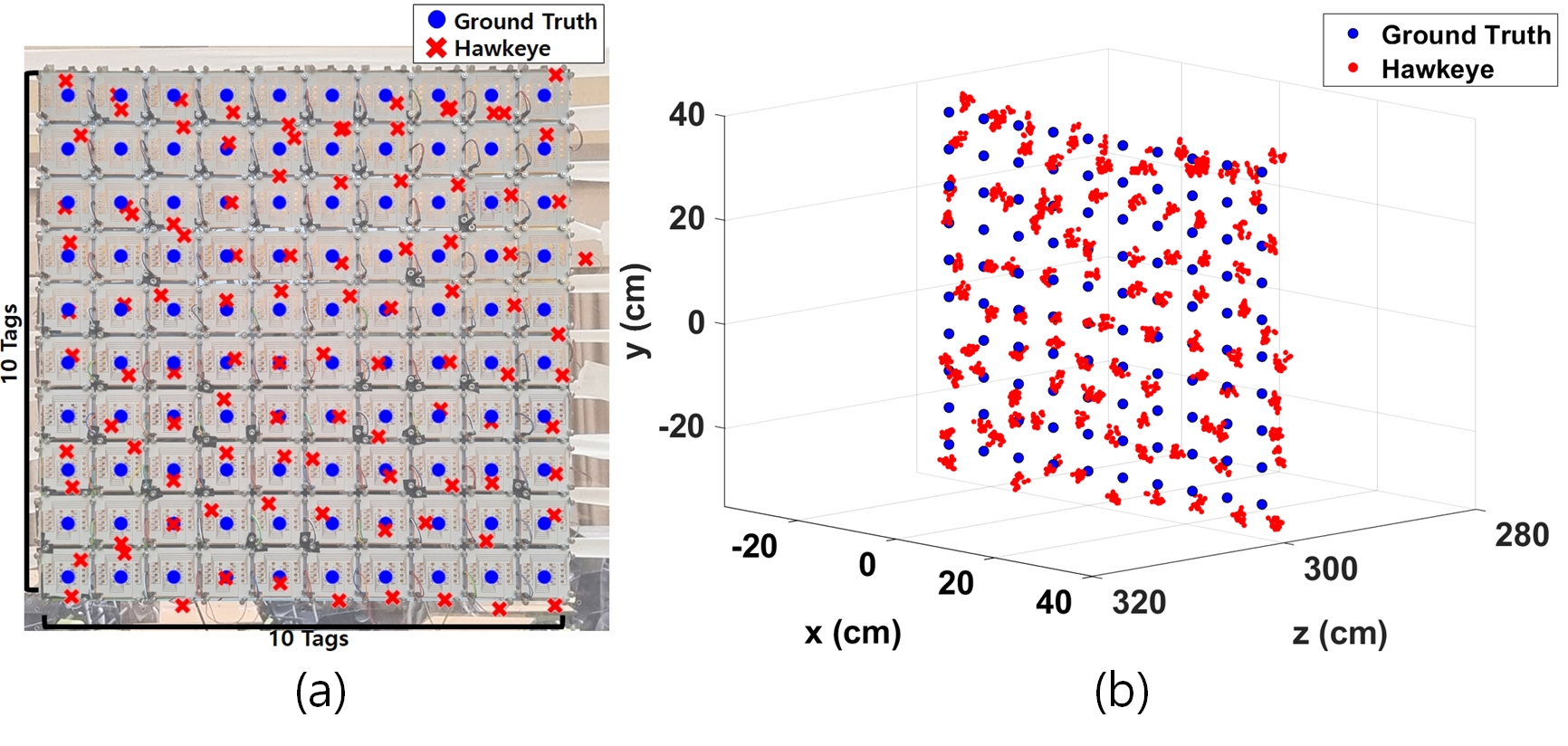
To verify the large-scale support of Hawkeye, a simultaneous, 3D localization experiment consisting of 100 tags is conducted in an indoor environment. Figure 28(a) depicts the arrangement of 100 tags, where they are deployed as 10 by 10 on a acrylic board. The tags are densely deployed with intervals of to demonstrate operation in harsh environments (e.g., items stacked up in the warehouse) where substantial coupling between tags exists. The 100 tags concurrently modulates with unique in between 100 kHz and 250 kHz. For 3D localization, three radars are attached to a wall as depicted in Figure 29. Each radars are located at , and coordinates, assuming is the 100 tags center. Figure 27 demonstrates the 100 tags localization processing result, where the successful localization of each tags resulting in 100 different envelope sincs are visible. Figure 28(b) depicts the the localization result of Hawkeye at scale, where all estimation results are shown as red cross around the ground truth. The CDF of large-scale 3D localization error is shown at Figure 30, showing median error of and percentile error of . For each , , dimension, the median error is , , , and percentile error is , , each. The concurrent localization of 100 tags verifies Hawkeye scalability at realistic settings.
6 Related Work
mmWave Systems and Sensing. mmWave systems have been proposed to exploit the large bandwidth [26, 31, 64, 12]. mmWave radars also utilize extensive bandwidth to achieve higher sensing accuracy [23, 9, 52, 28].
Backscatter. Backscatter offers extremely low-power signaling for power constrained scenarios [10, 16, 67, 36]. Backscatter system also facilitates low-power sensing, including RFID-based approaches [6, 59, 44, 30].
Backscatter/RFID Localization. As one of the representative implementation of backscatter systems, RFID-based localization techniques have long been discussed in the community [18, 20, 51, 57, 61]. Initial studies measure the amplitude, phase and the angle of arrival of the received signal [2, 3, 29, 65, 25, 66], which suffered from multi-path effects. Recent studies still suffer from low accuracy in practical scenarios due to limited bandwidth of RFID, including [13, 58, 48, 60, 62] which require knowledge on motion or reference tags to mitigate multi-path effects. While [33] emulates large bandwidth to achieve sub-centimeter accuracy, range is limited to room-scale scenarios to comply with FCC regulations. [55] utilize large bandwidth of mmWave FMCW radar to achieve range, but is still essentially limited to FMCW range resolution.
7 Conclusion
This paper presents Hawkeye, a mmWave backscatter localization that can achieve subcentimeter median accuracy at hectometer range, while using an affordable commodity radar (200 USD [17]) for the reader. Hawkeye simultaneously localizes 100 tags in only , and is capable of supporting up to 1024 tags in theory. Our design consists of (i) a new planar Van Atta Array tag that retro-reflects in both azimuth and elevation, combined with a low-loss FSK modulator, and (ii) a novel localization algorithm that achieves the localization performance of FMCW radar, while being immune to the tag oscillator frequency offset. Collectively, Hawkeye take a solid step towards bringing pervasive tag deployment and localization to practice.
References
- [1] Analog Devices. EVAL-TINYRAD. https://www.analog.com/en/design-center/evaluation-hardware-and-software/evaluation-boards-kits/eval-tinyrad.html.
- [2] D. Arnitz, K. Witrisal, and U. Muehlmann. Multifrequency continuous-wave radar approach to ranging in passive uhf rfid. IEEE transactions on microwave theory and techniques, 57(5):1398–1405, 2009.
- [3] S. Azzouzi, M. Cremer, U. Dettmar, R. Kronberger, and T. Knie. New measurement results for the localization of uhf rfid transponders using an angle of arrival (aoa) approach. In 2011 IEEE International Conference on RFID, pages 91–97. IEEE, 2011.
- [4] M. Bouet and A. L. Dos Santos. Rfid tags: Positioning principles and localization techniques. In 2008 1st IFIP Wireless Days, pages 1–5. Ieee, 2008.
- [5] M. Bouet and G. Pujolle. A range-free 3-d localization method for rfid tags based on virtual landmarks. In 2008 IEEE 19th international symposium on personal, indoor and mobile radio communications, pages 1–5. IEEE, 2008.
- [6] X. Chang, J. Dai, Z. Zhang, K. Zhu, and G. Xing. Rf-rvm: Continuous respiratory volume monitoring with cots rfid tags. IEEE Internet of Things Journal, 8(16):12892–12901, 2021.
- [7] R. Chaudhuri. Waves and Oscillations. Basic physics through problems series. New Age International, 2001.
- [8] K. Chawla, C. McFarland, G. Robins, and C. Shope. Real-time rfid localization using rss. In 2013 International Conference on Localization and GNSS (ICL-GNSS), pages 1–6. IEEE, 2013.
- [9] W. Chen, Y. Feng, M. Cardamis, C. Jiang, W. Song, O. Ghannoum, and W. Hu. Soil moisture sensing with mmwave radar. In Proceedings of the 6th ACM Workshop on Millimeter-Wave and Terahertz Networks and Sensing Systems, pages 19–24, 2022.
- [10] Z. Chi, X. Liu, W. Wang, Y. Yao, and T. Zhu. Leveraging ambient lte traffic for ubiquitous passive communication. In SIGCOMM, 2020.
- [11] K. M. B. et al. Omniscatter: Extreme sensitivity mmwave backscattering using commodity fmcw radar. In MobiSys, 2022.
- [12] M. K. Haider, Y. Ghasempour, D. Koutsonikolas, and E. W. Knightly. Listeer: mmwave beam acquisition and steering by tracking indicator leds on wireless aps. In MobiCom, 2018.
- [13] J. Han, C. Qian, X. Wang, D. Ma, J. Zhao, W. Xi, Z. Jiang, and Z. Wang. Twins: Device-free object tracking using passive tags. IEEE/ACM Transactions on Networking, 24(3):1605–1617, 2015.
- [14] Hiwonder. H5S. https://hiwonder.hk/collections/humanoid-robot/products/h5s-hiwonder-16dof-intelligent-humanoid-dancing-robot-supports-entertaimnet-display.
- [15] J.-S. G. Hong and M. J. Lancaster. Microstrip filters for RF/microwave applications. John Wiley & Sons, 2004.
- [16] K. Huang, R. Chen, and W. Gao. Rascatter: Achieving energy-efficient backscatter readers via ai-assisted power adaptation. In 2022 IEEE/ACM Seventh International Conference on Internet-of-Things Design and Implementation (IoTDI), pages 1–13. IEEE, 2022.
- [17] Infineon Technologies. DEMO DISTANCE2GO. https://www.infineon.com/cms/en/product /evaluation-boards/demo-distance2go/.
- [18] C. Jiang, Y. He, X. Zheng, and Y. Liu. Orientation-aware rfid tracking with centimeter-level accuracy. In 2018 17th ACM/IEEE International Conference on Information Processing in Sensor Networks (IPSN), pages 290–301. IEEE, 2018.
- [19] V. Kallnichev. Analysis of beam-steering and directive characteristics of adaptive antenna arrays for mobile communications. IEEE Antennas and Propagation Magazine, 43(3):145–152, 2001.
- [20] N. C. Karmakar et al. Chipless rfid tag localization. IEEE transactions on Microwave Theory and Techniques, 61(11):4008–4017, 2013.
- [21] Keysight. DSOX1204G. https://www.keysight .com/us/en/assets/7018-06411/data-sheets/5992-3484.pdf.
- [22] J. R. Klauder, A. C. Price, S. Darlington, and W. J. Albersheim. The theory and design of chirp radars. The Bell System Technical Journal, 39(4):745–808, 1960.
- [23] H. Kong, X. Xu, J. Yu, Q. Chen, C. Ma, Y. Chen, Y.-C. Chen, and L. Kong. m3track: mmwave-based multi-user 3d posture tracking. In Proceedings of the 20th Annual International Conference on Mobile Systems, Applications and Services, pages 491–503, 2022.
- [24] S. K. Koul and B. Bhat. Microwave and millimeter wave phase shifters, volume 2. Artech House Norwood, MA, 1991.
- [25] R. Kronberger, T. Knie, R. Leonardi, U. Dettmar, M. Cremer, and S. Azzouzi. Uhf rfid localization system based on a phased array antenna. In 2011 IEEE International Symposium on Antennas and Propagation (APSURSI), pages 525–528. IEEE, 2011.
- [26] J. O. Lacruz, D. Garcia, P. J. Mateo, J. Palacios, and J. Widmer. mm-flex: an open platform for millimeter-wave mobile full-bandwidth experimentation. In MobiSys, 2020.
- [27] Leica. DISTO D510. https://shop.leica-geosystems.com/sites/default/files/2020-12/D510_792312d_en.pdf.
- [28] H. Li, C. Xu, A. S. Rathore, Z. Li, H. Zhang, C. Song, K. Wang, L. Su, F. Lin, K. Ren, et al. Vocalprint: A mmwave-based unmediated vocal sensing system for secure authentication. IEEE Transactions on Mobile Computing, 2021.
- [29] X. Li, Y. Zhang, and M. G. Amin. Multifrequency-based range estimation of rfid tags. In 2009 IEEE International Conference on RFID, pages 147–154. IEEE, 2009.
- [30] X.-Y. Li, M. Yin, Y. Zhang, P. Yang, C. Wan, X. Guo, and H. Tan. Back-guard: Wireless backscattering based user sensing with parallel attention model. IEEE Transactions on Mobile Computing, 2022.
- [31] Z. Li, Y. Shu, G. Ananthanarayanan, L. Shangguan, K. Jamieson, and P. Bahl. Spider: A multi-hop millimeter-wave network for live video analytics. In 2021 IEEE/ACM Symposium on Edge Computing (SEC), pages 178–191. IEEE, 2021.
- [32] Z. Luo, Q. Zhang, Y. Ma, M. Singh, and F. Adib. 3d backscatter localization for fine-grained robotics. In 16th USENIX Symposium on Networked Systems Design and Implementation (NSDI 19), pages 765–782, 2019.
- [33] Y. Ma, N. Selby, and F. Adib. Minding the billions: Ultra-wideband localization for deployed rfid tags. In Proceedings of the 23rd annual international conference on mobile computing and networking, pages 248–260, 2017.
- [34] Macom. IV Data Madp-000907-14020. https://tinyurl .com/bddc6ypm.
- [35] Macom. MADP-000907-14020. https://cdn.macom.com/datasheets/MADP-000907-14020x.pdf.
- [36] A. Y. Majid, M. Jansen, G. O. Delgado, K. S. Yildirim, and P. Pawełłzak. Multi-hop backscatter tag-to-tag networks. In IEEE INFOCOM 2019-IEEE Conference on Computer Communications, pages 721–729. IEEE, 2019.
- [37] G. Mao, B. Fidan, and B. D. Anderson. Wireless sensor network localization techniques. Computer networks, 51(10):2529–2553, 2007.
- [38] M. Matin and A. Sayeed. A design rule for inset-fed rectangular microstrip patch antenna. WSEAS Transactions on Communications, 9(1):63–72, 2010.
- [39] M. H. Mazaheri, A. Chen, and O. Abari. mmtag: a millimeter wave backscatter network. In SIGCOMM, 2021.
- [40] Micro Crystal. CC1V-T1A. https://www.microcrystal.com/fileadmin/Media /Products/32kHz/Datasheet/CC1V-T1A.pdf.
- [41] Microsemi. Libero SoC v11.8. https://www.microsemi.com/product-directory/root/5485-libero-soc-v11-8-archive.
- [42] R. Miesen, F. Kirsch, and M. Vossiek. Holographic localization of passive uhf rfid transponders. In 2011 IEEE international conference on RFID, pages 32–37. IEEE, 2011.
- [43] D. L. Mills. Computer Network Time Synchronization: The Network Time Protocol. Taylor & Francis, 1 edition, 2010.
- [44] R. Nandakumar, V. Iyer, and S. Gollakota. 3d localization for sub-centimeter sized devices. In SenSys, 2018.
- [45] L. M. Ni, Y. Liu, Y. C. Lau, and A. P. Patil. Landmarc: Indoor location sensing using active rfid. In Proceedings of the First IEEE International Conference on Pervasive Computing and Communications, 2003.(PerCom 2003)., pages 407–415. IEEE, 2003.
- [46] A. Oppenheim and R. Schafer. Digital Signal Processing. Prentice Hall international editions. Prentice-Hall, 1975.
- [47] OptiTrack. PrimeX 13. https://optitrack.com/cameras/primex-13/.
- [48] A. Parr, R. Miesen, and M. Vossiek. Inverse sar approach for localization of moving rfid tags. In 2013 IEEE International Conference on RFID (RFID), pages 104–109. IEEE, 2013.
- [49] J. Reed and G. Wheeler. A method of analysis of symmetrical four-port networks. IRE Transactions on Microwave Theory and Techniques, 4(4):246–252, 1956.
- [50] L. Shangguan and K. Jamieson. The design and implementation of a mobile rfid tag sorting robot. In MobiSys, 2016.
- [51] Y. Shu, P. Cheng, Y. Gu, J. Chen, and T. He. Toc: Localizing wireless rechargeable sensors with time of charge. ACM transactions on sensor networks (TOSN), 11(3):1–22, 2015.
- [52] X. Shuai, Y. Shen, Y. Tang, S. Shi, L. Ji, and G. Xing. millieye: A lightweight mmwave radar and camera fusion system for robust object detection. In Proceedings of the International Conference on Internet-of-Things Design and Implementation, pages 145–157, 2021.
- [53] Skyworks. Si515. https://www.skyworksinc.com/-/media/Skyworks/SL/documents/public/data-sheets/Si515.pdf.
- [54] Soar-Xiang Tech. STMX1020-D. https://www.soared.com.tw/Content/Upload /files/micro-stage-series.pdf.
- [55] E. Soltanaghaei, A. Prabhakara, A. Balanuta, M. Anderson, J. M. Rabaey, S. Kumar, and A. Rowe. Millimetro: mmwave retro-reflective tags for accurate, long range localization. In MobiCom, 2021.
- [56] Toshiba. TAR5SB33. https://toshiba.semicon-storage.com /ap-en/semiconductor/product/power-management-ics/detail.TAR5SB33.html.
- [57] J. Wang, F. Adib, R. Knepper, D. Katabi, and D. Rus. Rf-compass: Robot object manipulation using rfids. In Proceedings of the 19th annual international conference on Mobile computing & networking, pages 3–14, 2013.
- [58] J. Wang and D. Katabi. Dude, where’s my card? rfid positioning that works with multipath and non-line of sight. In Proceedings of the ACM SIGCOMM 2013 conference on SIGCOMM, pages 51–62, 2013.
- [59] J. Wang, J. Xiong, X. Chen, H. Jiang, R. K. Balan, and D. Fang. Tagscan: Simultaneous target imaging and material identification with commodity rfid devices. In Proceedings of the 23rd Annual International Conference on Mobile Computing and Networking, pages 288–300, 2017.
- [60] L. Yang, Y. Chen, X.-Y. Li, C. Xiao, M. Li, and Y. Liu. Tagoram: Real-time tracking of mobile rfid tags to high precision using cots devices. In Proceedings of the 20th annual international conference on Mobile computing and networking, pages 237–248, 2014.
- [61] S. Yang, M. Jin, Y. He, and Y. Liu. Rf-prism: Versatile rfid-based sensing through phase disentangling. In 2021 IEEE 41st International Conference on Distributed Computing Systems (ICDCS), pages 1053–1063. IEEE, 2021.
- [62] J. Zhang, X. Liu, T. Gu, X. Tong, S. Chen, and K. Li. Siloc: A speed inconsistency-immune approach to mobile rfid robot localization. In IEEE INFOCOM 2021-IEEE Conference on Computer Communications, pages 1–10. IEEE, 2021.
- [63] P. Zhang, D. Bharadia, K. Joshi, and S. Katti. Hitchhike: Practical backscatter using commodity wifi. In SenSys, 2016.
- [64] R. Zhao, T. Woodford, T. Wei, K. Qian, and X. Zhang. M-cube: A millimeter-wave massive mimo software radio. In MobiCom, 2020.
- [65] J. Zhou and J. Shi. Rfid localization algorithms and applications—a review. Journal of intelligent manufacturing, 20(6):695–707, 2009.
- [66] J. Zhou, H. Zhang, and L. Mo. Two-dimension localization of passive rfid tags using aoa estimation. In 2011 IEEE International Instrumentation and Measurement Technology Conference, pages 1–5. IEEE, 2011.
- [67] F. Zhu, M. Ouyang, L. Feng, Y. Liu, X. Tian, M. Jin, D. Chen, and X. Wang. Enabling software-defined phy for backscatter networks. In Proceedings of the 20th Annual International Conference on Mobile Systems, Applications and Services, pages 330–342, 2022.