Engineering sub-Poisson light in a simple mirror and beam splitter system
Abstract
Vacuum fluctuation, which is the intrinsic nature of an electric field can be measured via homodyne detection. Moreover, electric field intensity fluctuation are also related to vacuum fluctuations. Squeezed vacuum and sub-Poisson light can be obtained by controlling the vacuum fluctuation using noble nonlinear interaction. Based on the squeezed vacuum by inserting a mirror on the unused part of the beam splitter was proposed in 1994, we present the mode matching method for the vacuum and light fields. Light intensity fluctuations also can be reduced by inserting a mirror on the unused part of the beam splitter. To obtain sub-Poisson light as a function of the distance between the mirror and detector, a detector with a thinner active layer than the wavelength is required.
pacs:
03.67.-a,03.70.+k, 03.65.YzI Introduction
When a single photon is in a particular mode, according to the particle nature of light, photons will be sequentially found in that mode. The probability of finding a photon is proportional to the absolute square of the wave function related to the electromagnetic wave. Vacuum fluctuations are related to the spatial characteristics of the electromagnetic wave. The spontaneous decay caused by the vacuum can be suppressed in cavities Jhe1987 . Theoretical and experimental studies have beem conducted on methods to change the vacuum fluctuations near mirrorssun1995 ; sun1994 ; wadood .
In this study, in contrast to previous studies on the vacuum noise characteristics of light using a homodyne detector, we calculate the intensity fluctuations when photons are directly measured using photon counter. The obtained results are similar to those obtained in previous studies, but herein we predict the results considering mode matching in the experiment.
In section II, the fluctuation of light that can be measured using a detector is calculated with a mirror placed on one side of the beam splitter. In section III, an experimental device is proposed for perfect mode matching, and in the last section, the practical limits of the vacuum fluctuation near the mirror are discussed.
II Vacuum fluctuation near a mirror.
An electric field can be written as
| (1) |
where
| (2) |
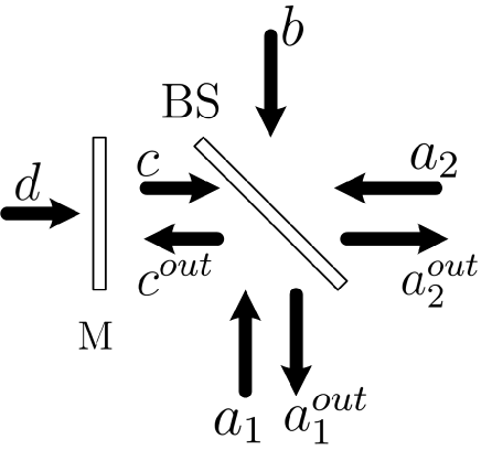
Here, and are the wave number and angular frequency of the laser, respectively, and have usual meanings, and is the normalization volumeyariv . Considering the laser mode in Fig. 1, the modes and can be written as
| (3) |
where the modes and can be written as
Then the electric field in fluctuating vacuum modes at is
| (4) | |||||
where () is the reflectance(transmittance) of the mirror and () is the reflectance (transmittance) of the beam splitter, () is the distance from the mirror (laser) to the detector. is related to the vacuum source behind the mirror and it can be any number. We add the factor for the normalization of the vacuum fluctuation. The vacuum mode () at the detector is the reflected vacuum mode () at the mirror. If two modes are perfectly matched the in Eq. 4 is 1 and the two counterpropagating modes yield the standing wave modesun1994 ; sun1995 . If , the fluctuation value from Eq. 7 becomes , it is the square of the constant dc current . In other words, if we directly measure the fluctuation of the laser intensity, the fluctuation is dependent on the distance () between the mirror and the detector. Even in photo counting experiments, the photon number fluctuation is related to the vacuum fluctuation, therefor, the photon number fluctuation is also depend on the distance .
If we used the photodetetion theory detection with instantaneous response of the photodetector response ,
| (5) |
where we normalize the photocurrent. If the electric field of the local oscillator is considerably greater than the vacuum field, the terms containig have physical significance. When the constant dc current is neglected, Eq. 5 yields
| (6) | |||||
We then evaluate the square of the photocurrent to determine the fluctuation. After squaring Eq. 6, we find the photocurrent fluctuation as follows:
| (7) |
If , the fluctuation value from Eq. 7 becomes , which is the square of the constant dc current . In other words, if we directly measure the laser intensity fluctuation, the fluctuation is dependent on the distance () between the mirror and detector. Even in the photo counting experiment, the photon number fluctuation is related to the vacuum fluctuation; therefore, the photon number fluctuation is also dependent on the distance .
If we consider practical limits such as finite linewidth and finite absorption length, Eq. 7 will change as followsref7 ; sun1995 .
| (8) | |||||
where is the line width of the local oscillator beam with Gaussian line width distribution functions. is the absorption coefficient, is the detector active length, and . We assumed that the probability that a photon is converted into an electron hole pair at distance from the surface of the detector’s active region is ref8 .
The two coefficients and depend on the mode matching condition. Even when we used the total mirror, if the mode from the mirror is not perfectly matched with the mode from the laser, the effective reflectance can not be . Furthermore, the mode to the mirror is reflected by the mirror and then meets at the detector. At the detector, if two counter-propagating modes are not exactly matched, the coefficient cannot be . To evaluate this mode matching condition, we assume that the amplitude envelope of the electromagnetic wave in the transverse plane is given by a Gaussian function.
Considering the Gaussian modes saleh
| (9) |
, where is the radius of the beam waist and
| (10) |
and is defined as follows:
| (11) |
First, we assume that the laser and vacuu modes have the same beam waist at the detector. Then the laser and vacuum modes are perfectly matched; thus, . On the other hand, the vacuum starting from the detector propagates to the mirror and reflects at the mirror. The returned vacuum is not the same . The coefficient can be calculated as follow:
| (12) | |||||
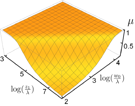
In Fig. 2, is plotted as a function of and , where is the distance between the mirror and detector We assume that the detector and mirror are large enough that all the waves are detected and reflected. If the distance between the mirror and detector and the size of the beam waist are small enough, the coefficient remains near .
If we consider the case where the vacuum field has waist at the mirror, the coefficient automatically becomes due to the symmetry, but the vacuum field at the detector does not matche the laser field . We assumed that the laser field has beam waist at the detector, and the vacuum field has a beam waist at the mirror. Then the effective reflectance becomes
| (13) | |||||
where .
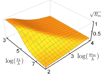
In Fig. 3, is plotted as a function of and , where is the distance between the mirror and detector. We set to . Additionally, we also assume that the detector and mirror are large enough that all the waves are detected and reflected. The coefficient can be 1 only when the distance between the mirror and detector is small and the size of the beam waist is sufficiently small.
The mode matching condition is crucial for detecting the modulation effect of the vacuum fluctuation near the mirror, as denoted by Eq. 8. With the usual setup, we can not satisfy the conditions and . In the next section, we suggest a noble experimental setup that satisfies two mode-matching conditions.
III Set up for mode matching
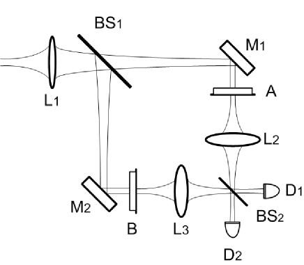
For a laser that has a Gaussian transverse mode, we have to establish a vacuum mode that also has a Gaussian transverse mode. Fig. 4 displays the setup for perfect mode matching between the laser light mode and a vacuum mode.
The laser used in the experiment passes through lens and is divided into two by the beam splitter (). The laser is a Gaussian beam and it proceeds according to the Gaussian approximation. The light passing through and traveling to mirror reaches the partial mirror and yields a beam waist on the side surface of . Similarly, the light reflecting from the mirror passes through the partial reflector and yields a beam waist on the side surface of .
The light passing through and passes through the and of the same focal length, respectively, and yields another beam waist on the detector surface. The transmittance of light passing through from is almost 0, and the reflectance of light stemming from the side is almost 1. In this way, if the mode is perfectly matched using the light passing through and , an experimental setup can be established wherein one side of the beam splitter is a mirror ().
Using this method, the degree of mode matching can be increased compared to that when the experiment is performed by simply placing a plane mirror on one side of the beam splitter. Additionally the experimental constraints caused by the mode matching can be overcome. The experimental setup in Fig. 4 enables the measurement of how the vacuum fluctuations of the light passing through the beam splitter change when a mirror is placed on one side of the beam splitter.
IV Conclusion and Discussion.
The quantum nature of photons is highly dependent on their vacuum fluctuations. Vacuum fluctuations can be directly measured via homodyne detection. The fluctuation of one quadrature of the vacuum can be less than that of the usual vacuum, e.g., squeezed vacuum. Light intensity fluctuations are also dependent on vacuum fluctuations. Sub-Poisson light can be generated by controlling the vacuum fluctuations based on the nonlinear interaction of light and matter. In this study, we proposed the modulation of vacuum fluctuations by inserting a mirror on the unused part of the beam splitter in a homodyne measuring system. Furthermore, we calculated the effect of the line width of the laser and the thickness of the detector layer. The line width can be practically reduced to modulate vacuum fluctuations, but the decrease of the thickness of the detector to modulate vacuum fluctuations is challenging. We calculated the effect of mode matching between the vacuum and light fields and showed that the degree of mode matching obtained by adding a simple mirror in the unused beam splitter may not be sufficient to modulate the vacuum fluctuations. We present the perfect mode matching method for the vacuum and light fields. Then, the light intensity fluctuations can be reduced by inserting a beam splitter and a mirror. We still require a detector with an active layer thinner than the wavelength to obtain a sub-Poisson light as a function of the distance between the mirror and detector. We expect that our simple method of reducing vacuum fluctuations will play a great role in quantum information science.
References
- (1) W. Jhe, A Anderson, E. A. Hinds, D. Meschede, L. Moi, and S. Haroche, Phys. Rev. Lett. 58, 666 (1987)
- (2) S. H. Youn, J. H. Lee, J. S. Chang, Opt. and Quant. Elec. 27, 355 (1995)
- (3) S. H. Youn, J. H. Lee, J. S. Chang, International Workshop on Squeezed States and Uncertainty Relations, N95-13921 (1994)
- (4) S. A. Wadood, J. T, Schultz, A. N. Vamivakas, and C.R. Stroud Jr, J. of Mod. Opt. 66, 1116 (2019)
- (5) A. Yariv, Quantum Electronics 3rd ed., John Wiley & Sons. Inc, (1989)
- (6) P. D. Drummond, Phys. Rev. A 35, 4253 (1987).
- (7) B. Yurke, Phys. Rev. A 32, 311 (1985)
- (8) A. E. Siegman, Laser (Oxford University Press, Oxford, 1986 )
- (9) S. M. Sze, Semiconductor Devices Physics and Technology (AT&T Bell Lab. Murray Hill, New Jersey, 1985)
- (10) B. E. A. Saleh, M. C. Teich, Fundamentals of Photonics ( Wiley, Nw York, 1991)