On the minimum transport required to passively suppress runaway electrons in SPARC disruptions
Abstract
In [V.A. Izzo et al 2022 Nucl. Fusion 62 096029], state-of-the-art modeling of thermal and current quench (CQ) MHD coupled with a self-consistent evolution of runaway electron (RE) generation and transport showed that a non-axisymmetric () in-vessel coil could passively prevent RE beam formation during disruptions in SPARC, a compact high-field tokamak projected to achieve a fusion gain in DT plasmas. However, such suppression requires finite transport of REs within magnetic islands and re-healed flux surfaces; conservatively assuming zero transport in these regions leads to an upper bound of RE current compared to of pre-disruption plasma current. Further investigation finds that core-localized electrons, within and with kinetic energies , contribute most to the RE plateau formation. Yet only a relatively small amount of transport, i.e. a diffusion coefficient , is needed in the core to fully mitigate these REs. Properly accounting for (i) the CQ electric field’s effect on RE transport in islands and (ii) the contribution of significant RE currents to disruption MHD may help achieve this.
Keywords: Runaway electrons, passive mitigation, transport, disruptions, SPARC
1 Introduction
In [1, 2], a novel method was proposed for passive mitigation of relativistic “runaway electrons” (REs) generated during tokamak plasma disruptions: First, an in-vessel, non-axisymmetric coil would be passively energized through mutual coupling to the plasma current during the disruption’s current quench (CQ); then, the resulting magnetic field perturbation would enhance stochasticity and transport such that the RE loss rate would dominate the growth rate, thus preventing RE beam formation.
In [3], such a “Runaway Electron Mitigation Coil” (REMC) was proposed for the SPARC tokamak [4], a high-field (), compact (, ) device currently under construction in Devens, Massachusetts, USA. The present REMC design has a predominantly structure and is located on the outboard wall; a similar coil is planned for the DIII-D tokamak, but on the inboard wall [5]. Several aspects of the SPARC “Primary Reference Discharge” (PRD) make the RE problem challenging: a large plasma current () can lead to dangerous exponential RE growth; high core temperatures can cause enhanced primary and hot-tail generation; DT fuel provides a seed of non-thermal electrons through tritium beta decay; and high energy gammas from activated materials could accelerate electrons via Compton scattering.
However, in [6], modeling of the PRD’s worst-case-scenario CQ () showed complete prevention of RE beam formation with the REMC – and of RE current without it. The modeling workflow included four steps: First, the mutual couplings of all toroidally conducting structures were simulated in COMSOL [7] to evaluate the REMC’s vacuum electromagnetic fields during the worst-case CQ. Second, these magnetic fields were applied at the boundary of a nonlinear, 3D NIMROD [8] simulation to assess the plasma response and total fields. Third, the stochastic magnetic fields were input into the orbit-following code ASCOT5 to calculate the advective and diffusive transport [9] of energetic electrons. Finally, these transport coefficients – as functions of energy, pitch, and radius – were supplied to the hybrid fluid-kinetic code DREAM [10] for self-consistent evolution of the RE population. Importantly, in both NIMROD and DREAM, the REMC vacuum fields and transport coefficients, respectively, were evolved as functions of and not time explicitly.
More recently, in [11], both the thermal quench (TQ) and CQ were modeled for the SPARC PRD and REMC; the results of this study – which bound the maximum expected RE current – are summarized in Section 2. Section 3 further explores these bounds in RE phase space, as well as the minimum transport needed to fully prevent RE beam formation. Finally, results and opportunities for future modeling are discussed in Section 4.
2 REMC efficacy during the thermal and current quenches
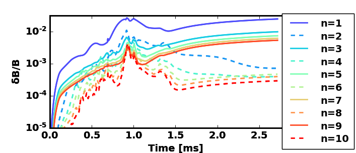
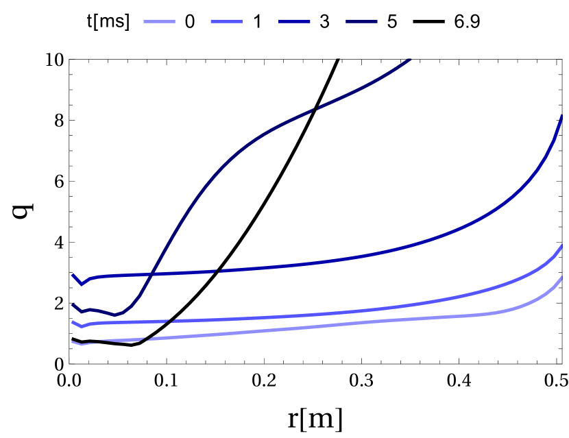
The same workflow presented in [6] and summarized in Section 1 was used in [11] to assess the SPARC REMC’s efficacy for a full PRD mitigated disruption, i.e. including both the TQ and CQ. Here, the TQ ( in duration) was induced by neon radiation, as in a scenario where massive gas injection was employed. The main results are captured in Figs. 1 and 2. The pre-disruption safety factor () profile is shown at in Fig. 1(a) with and around a normalized poloidal flux value of . During the TQ, i.e. the first of the simulation, the plasma current decreases slightly, with the -spike denoting the start of the CQ. Around that time, the magnetic perturbation amplitudes first peak (see Fig. 1(b)), and strong nonlinear coupling among odd and even toroidal harmonics is observed. Poincaré plots of magnetic field lines, in Fig. 1(a), also show high stochasticity during this period.
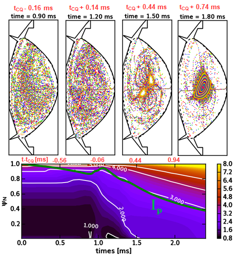
However, from , increases from 1 to 2, and beyond , the REMC is no longer resonant with the plasma core (refer to Figure 1 in [6] for more details). Although the predominantly odd externally applied fields continue to grow as a the coil current continues to increase, these are now largely non-resonant fields that do not perturb the flux surfaces, and the nonlinearly excited resonant field components, both odd and even, decay away. Thus, small islands start to reform, re-healing as closed flux surfaces by . Note that the contribution from REs to the MHD are not included in these NIMROD simulations, but the back-reaction is expected to be small for low RE currents early on. This will be discussed further in Section 4.
Figure 2 shows the self-consistent evolution of Ohmic and RE currents from DREAM, including the advective and diffusive transport calculated by ASCOT5 in DREAM’s fluid transport model [12]. Note that the time bases of the DREAM and NIMROD simulations are not exactly the same; instead, the DREAM simulation is initialized with profiles close to the time of NIMROD’s -spike. Importantly, the TQ in DREAM is only modeled for the final of NIMROD’s TQ because DREAM requires a monotonic variation of the plasma current from which to map transport coefficients. These transport coefficients evolve with the plasma current until the final -value of the NIMROD simulation; then, they are held constant in time (see the vertical dashed line in the upper part of Fig. 2).222 To enforce transport ambipolarity in DREAM, any change of the electron density on a given flux surface due to transport is compensated by a change in the bulk electron density of similar size but opposite sign.
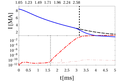
Two scenarios for the RE current are depicted in Fig. 2: In the first, the transport coefficients are applied as calculated throughout the entire plasma domain, i.e. even inside the re-healed flux surfaces, and the RE current remains negligibly low (). However, in the second case, transport inside islands and re-healed flux surfaces is set to zero, which is perhaps overly conservative. (Explicitly, wherever .) The result is a RE plateau with current . While this value is an improvement upon the of RE current expected with no REMC [3, 6], it is likely the pessimistic upper bound on the true value.
Here, it is important to note that the initial hot-tail seed can be sensitive to the TQ cooling time prescribed in DREAM. In the CQ-only modeling effort of [6], a TQ from to led to a seed which was then dissipated by the REMC, with similar as that in Fig. 1(b). Further reducing the TQ time to resulted in a much higher transient RE beam current of , which was still suppressed by the REMC. These results are consistent with all test-particle REs losing confinement during the TQ in NIMROD for the scenario modeled in this paper [11]. The inclusion of TQ transport in DREAM, as a function of non-monotonic variation, is left for future work.
3 Investigating transport inside re-healed flux surfaces
This section explores further the ten-order-of-magnitude difference in the predicted RE current when transport is/not accounted for within NIMROD’s islands and re-healed flux surfaces. Radial profiles of the diffusion coefficient () are shown in Fig. 3(a), also as a function of normalized electron momentum, at the last NIMROD simulation time; the values shown are taken at a representative electron pitch . There are a few important notes here: (i) the diffusion coefficients span five orders of magnitude from the plasma core to edge; (ii) though not shown, the advection coefficients are of similar magnitude (); and (iii) both transport coefficients are relatively insensitive to the electron pitch in the relevant range (see Figure 3 in [6]).
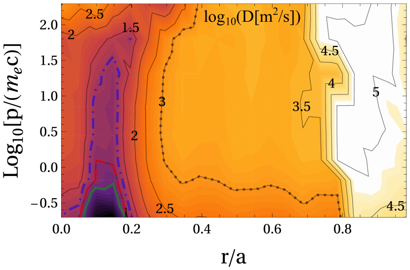
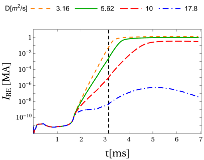
In Fig. 3(a), general trends are seen of rapidly decreasing transport with decreasing radius and relative insensitivity to electron energy. However, there is a clear feature of “very low” transport () for electrons localized in the core () and with energies (). Figure 3(b) shows the time-evolution of RE current when the transport coefficients are zeroed in different regions of the phase space in Fig. 3(a).333Note that the diffusivity is used for discrimination of the phase space regions, while the advection coefficients (not shown here) are also filtered in the same regions. The “base case” is wherever , which effectively includes the entire core, , and leads to the previously seen RE beam. Yet reducing this threshold to leads to negligible RE current. Thus, it is primarily the electron population within , i.e. localized in and with kinetic energies (), which contributes most to RE plateau formation.
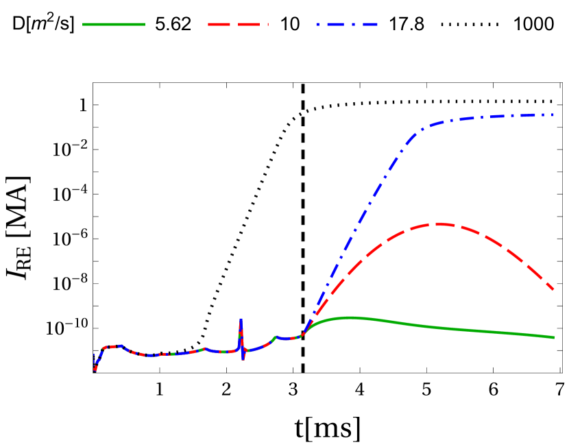
This problem can be looked at from another angle: What is the minimum transport needed to fully suppress RE plateau formation? More specifically, within the region of phase space where in Fig. 3(a) (that mostly coincides with the re-healed flux surface region), which constant value of is sufficient to yield negligible RE current? As seen in Fig. 4, full RE beam prevention is only achieved somewhere in the range . Therefore, compared to the highly diffusive edge region (), a relatively small amount of core transport is needed. Importantly, note that the advection coefficient is set to the same value as in these phase space regions, but almost identical results are found when setting , as diffusion dominates in the narrow radial region of re-healed flux surfaces (as long as ).
4 Discussion and summary
From the previous sections, it is clear that zeroing the transport in the core () in DREAM is too conservative and pessimistic, resulting in a RE beam. Even so, it is important to note that this current is 5-6 times less than that expected for an unmitigated RE beam, i.e. no REMC, so even this conservative base case could be considered successful. ASCOT5 simulations evaluate diffusion coefficients spanning in the core, but encouragingly only is needed in that region to completely suppress a RE beam. Perhaps this is one reason why many tokamaks struggle to generate RE plateaus via “natural” disruptions (as in Alcator C-Mod [13, 14], for example), and instead resort to special “recipes,” although lower plasma current and thus lower avalanching certainly also play a role.
However, it is not yet known whether this level of transport is achievable in SPARC . In [11], it was noted that the degree of field line stochastization predicted by NIMROD could be affected by several approximations, most notably the presence of a close, ideal wall which tends to limit MHD mode growth. This approximation will be explored further in future resistive-wall studies, and perhaps this minimum -value will even decrease.
We can also approach this from another direction: In what ways can the REMC design be modified to achieve throughout the plasma? Perhaps most straightforward, the coil could be moved closer to the plasma and farther from the VV. This would (i) improve the plasma-coil mutual coupling and reduce the coil’s self-inductance, thereby increasing the induced coil current, (ii) decrease image currents in the conducting wall, and (iii) enhance the magnetic perturbation amplitude in the core. Perhaps a design metric could be the expected diffusion coefficient computed from vacuum fields à la [15], . The coil resistance could also be lowered by changing the coil cross-section, length, and material (resistivity). That said, many other factors constrain the design, like available space, forces and stresses, heating, and more.
As discussed in [6], both advection and diffusion tend to increase with RE energy, but there is a roll-over when the energetic electron drift orbits effectively average over large regions of stochasticity (see Figure 3 in [6] or [16, 17] and others for further details). However, for REs within healed flux surfaces, perhaps large orbits could lead to “excursions” into stochastic fields, thus enhancing transport. For example, KORC simulations in [16] found that REs with Larmor radii similar to island widths could escape them. In addition, the same electric field accelerating REs causes them to drift radially [18], and this was not accounted for in these ASCOT5 simulations, but will be pursued in the future.444See [17] for simulations of passing and trapped REs during an ITER CQ, including the effects of collisions and the electric field.
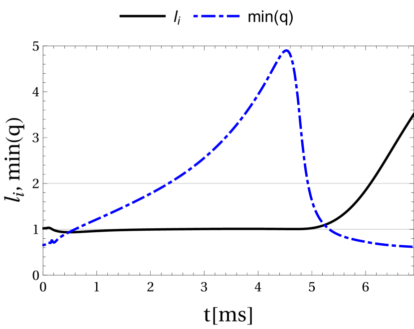
Perhaps most importantly, the effect of the RE population itself on the magnetic field and MHD has not yet been fully assessed. Figure 5 shows the time-evolution of the -profile, its minimum value, and the internal inductance () in DREAM for the base case. Although slightly later in time than in Fig. 1(a), the central safety factor also surpasses ; however, unlike the NIMROD results, the increasing RE current then reduces at and at . Thus, in theory, the REMC should regain resonance in the core beyond , thereby enhancing transport and reducing the RE current, but this was not captured in the current workflow. A destructive kink instability might also be expected, as seen in experiment [19, 20], for such low and high .
Even then it is not clear what overall effect this self-regulation would have on the RE beam which already has a current by (for the base case with no island transport). Luckily, the Ohmic current has almost completely decayed by then, and the relatively long L/R time () of the REMC will maintain the coil current and its perturbative effect. Furthermore, any additional transport within the re-healed flux surfaces will help lower this quasi-stationary RE current. A fluid RE model that could capture this effect has been incorporated into the JOREK [21, 22] and M3D-C1 [23] MHD codes; a similar model is being implemented in NIMROD [24] and benchmarked against the existing codes. Its application to the SPARC REMC will be pursued in future work.
Acknowledgments
Supported by Commonwealth Fusion Systems, Swedish Research Council (Dnr. 2018-03911), US DOE Award Numbers DE-FC02-04ER54698 and DE-FG02-95ER54309. This work has been carried out within the framework of the EUROfusion Consortium, funded by the European Union via the Euratom Research and Training Programme (Grant Agreement No 101052200 – EUROfusion). Views and opinions expressed are however those of the author(s) only and do not necessarily reflect those of the European Union or the European Commission. Neither the European Union nor the European Commission can be held responsible for them.
References
References
- [1] Allen H Boozer. Two beneficial non-axisymmetric perturbations to tokamaks. Plasma Phys. Control. Fusion, 53:84002–84008, 2011.
- [2] H. M. Smith, A. H. Boozer, and P. Helander. Passive runaway electron suppression in tokamak disruptions. Physics of Plasmas, 20(7), 2013.
- [3] R. Sweeney, A.J. Creely, J. Doody, T. Fülöp, D.T. Garnier, R. Granetz, M. Greenwald, L. Hesslow, J. Irby, V.A. Izzo, R.J. La Haye, N.C. Logan, K. Montes, C. Paz-Soldan, C. Rea, R.A. Tinguely, O. Vallhagen, and J. Zhu. MHD stability and disruptions in the SPARC tokamak. Journal of Plasma Physics, 2020.
- [4] A. J. Creely, M. J. Greenwald, S. B. Ballinger, D. Brunner, J. Canik, J. Doody, T. Fülöp, D. T. Garnier, R. Granetz, T. K. Gray, C. Holland, N. T. Howard, J. W. Hughes, J. H. Irby, V. A. Izzo, G. J. Kramer, A. Q. Kuang, B. LaBombard, Y. Lin, B. Lipschultz, N. C. Logan, J. D. Lore, E. S. Marmar, K. Montes, R. T. Mumgaard, C. Paz-Soldan, C. Rea, M. L. Reinke, P. Rodriguez-Fernandez, K. Särkimäki, F. Sciortino, S. D. Scott, A. Snicker, P. B. Snyder, B. N. Sorbom, R. Sweeney, R. A. Tinguely, E. A. Tolman, M. Umansky, O. Vallhagen, J. Varje, D. G. Whyte, J. C. Wright, S. J. Wukitch, and J. Zhu. Overview of the SPARC tokamak. Journal of Plasma Physics, 86(5):865860502, oct 2020.
- [5] D.B. Weisberg, C. Paz-Soldan, Y.Q. Liu, A. Welander, and C. Dunn. Passive deconfinement of runaway electrons using an in-vessel helical coil. Nuclear Fusion, 61(10):106033, sep 2021.
- [6] R.A. Tinguely, V.A. Izzo, D.T. Garnier, A. Sundström, K. Särkimäki, O. Embréus, T. Fülöp, R.S. Granetz, M. Hoppe, I. Pusztai, and R. Sweeney. Modeling the complete prevention of disruption-generated runaway electron beam formation with a passive 3D coil in SPARC. Nuclear Fusion, 61(12):124003, nov 2021.
- [7] COMSOL Inc. COMSOL, 2020. http://www.comsol.com/products/multiphysics/.
- [8] C R Sovinec, A H Glasser, T A Gianakon, D C Barnes, R A Nebel, S E Kruger, S J Plimpton, A Tarditi, M S Chu, and the NIMROD Team. Nonlinear Magnetohydrodynamics Simulation Using High-order Finite Elements. J. Comput. Phys., 195(1):355–386, mar 2004.
- [9] Eero Hirvijoki, Otto Asunta, Tuomas Koskela, Taina Kurki-Suonio, Juho Miettunen, Seppo Sipilä, Antti Snicker, and Simppa Äkäslompolo. Ascot: Solving the kinetic equation of minority particle species in tokamak plasmas. Computer Physics Communications, 185(4):1310–1321, 2014.
- [10] Mathias Hoppe, Ola Embreus, and Tünde Fülöp. Dream: A fluid-kinetic framework for tokamak disruption runaway electron simulations. Computer Physics Communications, 268:108098, 2021.
- [11] V.A. Izzo, I. Pusztai, K. Särkimäki, A. Sundström, D.T. Garnier, D. Weisberg, R.A. Tinguely, C. Paz-Soldan, R.S. Granetz, and R. Sweeney. Runaway electron deconfinement in SPARC and DIII-D by a passive 3D coil. Nuclear Fusion, 62(9):096029, aug 2022.
- [12] P. Svensson, O. Embreus, S. L. Newton, K. Särkimäki, O. Vallhagen, and T. Fülöp. Effects of magnetic perturbations and radiation on the runaway avalanche. Journal of Plasma Physics, 87(2):905870207, 2021.
- [13] R.S. Granetz. Disruption runaway experiment with Lower Hybrid seeding in low-elongation limited plasmas. In ITPA MHD Topical Meeting, Seoul, Korea, 2010.
- [14] V.A. Izzo, E.M. Hollmann, A.N. James, J.H. Yu, D.A. Humphreys, L.L. Lao, P.B. Parks, P.E. Sieck, J.C. Wesley, R.S. Granetz, G.M. Olynyk, and D.G. Whyte. Runaway electron confinement modelling for rapid shutdown scenarios in diii-d, alcator c-mod and iter. Nuclear Fusion, 51(6):063032, may 2011.
- [15] A. B. Rechester and M. N. Rosenbluth. Electron heat transport in a tokamak with destroyed magnetic surfaces. Phys. Rev. Lett., 40:38–41, Jan 1978.
- [16] L. Carbajal, D. del Castillo-Negrete, and J. J. Martinell. Runaway electron transport in stochastic toroidal magnetic fields. Physics of Plasmas, 27(3):032502, 2020.
- [17] Konsta Särkimäki, Javier Artola, Matthias Hoelzl, and the JOREK Team. Confinement of passing and trapped runaway electrons in the simulation of an ITER current quench. Nuclear Fusion, 62(8):086033, jun 2022.
- [18] Xiaoyin Guan, Hong Qin, and Nathaniel J. Fisch. Phase-space dynamics of runaway electrons in tokamaks. Physics of Plasmas, 17(9):092502, 2010.
- [19] Huishan Cai and Guoyong Fu. Influence of resistive internal kink on runaway current profile. Nuclear Fusion, 55(2):022001, jan 2015.
- [20] C Paz-Soldan, NW Eidietis, YQ Liu, D Shiraki, AH Boozer, EM Hollmann, CC Kim, and A Lvovskiy. Kink instabilities of the post-disruption runaway electron beam at low safety factor. Plasma Physics and Controlled Fusion, 61(5):054001, 2019.
- [21] V Bandaru, M Hoelzl, FJ Artola, G Papp, and GTA Huijsmans. Simulating the nonlinear interaction of relativistic electrons and tokamak plasma instabilities: Implementation and validation of a fluid model. Physical Review E, 99(6):063317, 2019.
- [22] V Bandaru, M Hoelzl, C Reux, O Ficker, S Silburn, M Lehnen, N Eidietis, JET Contributors, JOREK Team, et al. Magnetohydrodynamic simulations of runaway electron beam termination in jet. Plasma Physics and Controlled Fusion, 63(3):035024, 2021.
- [23] Chen Zhao, Chang Liu, Stephen C Jardin, and NM Ferraro. Simulation of MHD instabilities with fluid runaway electron model in M3D-C1. Nuclear Fusion, 60(12):126017, 2020.
- [24] AP Sainterme, CR Sovinec, and Ge Wang. Development of a reduced fluid model for runaway electrons in NIMROD simulations. In APS Division of Plasma Physics Meeting Abstracts, volume 2020, pages PP12–035, 2020.