Separable Tendon-Driven Robotic Manipulator with a Long, Flexible, Passive Proximal Section
Abstract
This work tackles practical issues which arise when using a tendon-driven robotic manipulator (TDRM) with a long, flexible, passive proximal section in medical applications. Tendon-driven devices are preferred in medicine for their improved outcomes via minimally invasive procedures, but TDRMs come with unique challenges such as sterilization and reuse, simultaneous control of tendons, hysteresis in the tendon-sheath mechanism, and unmodeled effects of the proximal section shape. A separable TDRM which overcomes difficulties in actuation and sterilization is introduced, in which the body containing the electronics is reusable and the remainder is disposable. An open-loop redundant controller which resolves the redundancy in the kinematics is developed. Simple linear hysteresis compensation and re-tension compensation based on the physical properties of the device are proposed. The controller and compensation methods are evaluated on a testbed for a straight proximal section, a curved proximal section at various static angles, and a proximal section which dynamically changes angles; and overall, distal tip error was reduced.
1 Introduction
Tendon-driven robotic manipulators (TDRM) have been used for various applications, such as remote inspection and maintenance in aerospace, minimally invasive surgery in medicine, and general search and rescue. They are preferred in these areas for their ability to maneuver in tight spaces in a compliant and safe manner. Devices have been developed in the medical domain for cardiac catheterization [1, 2, 3], and bronchoscopy [4, 5, 6]. Some of these devices are “flexible-steerable” as classified by Dupont et al. [7], meaning they are comprised of a steerable articulation section and a long, passive proximal section between the articulation section and the actuators. Such devices are particularly difficult to model and control accurately, and the proximal section is not included in the state-of-the-art kinematic and dynamic models. Devices with sensors such as Electromagnetic (EM) sensors (e.g., [6]) or Fiber bragg grating (FBG) based sensors (e.g., [5, 8, 9]) can provide a measure of shape and thereby circumvent the unmodeled behavior of the proximal section via closed-loop control. However, some devices, such as heart catheters, are one-time or limited-time use, meaning that it would be too costly to implement such sensors and that the unmodeled behavior cannot be compensated as with the aforementioned devices.
We introduce a separable TDRM for a practical setting. The separable design tackles the issue of reusability that is common among medical devices, where the part which interacts with the anatomy is disposable and the part containing the actuators is reusable. In addition, we utilize a practical model and calibration method for our proposed mechanism so that the four tendons are actuated simultaneously, allowing for precise tip control and mitigating issues with conventional devices, such as dead-zone and hysteresis, with simple linear compensation. We consider an open-loop controller since many available devices [2, 10] are used without position-tracking sensors at the tip due to costs and single use. We analyze the effect of the shape of the passive proximal section for different compensation types and offer insight on how this behavior might be accounted for in open and closed-loop systems.
2 Related Works
The tendon-sheath mechanism facilitates maneuverability and compliance in highly constrained anatomies by allowing for a long, thin, flexible, proximal tail-like structure. The TDRM is an actuation method that has been used in many therapeutic [11, 12, 13, 14, 15, 16] and real-time diagnostic (e.g., endoscope [17, 18, 19, 20, 21], and Intracardiac echocardiography (ICE) [22, 23, 24]) manipulators. The increased compliance of tendon-driven manipulators is not without drawbacks. Much work has gone into accurately modeling the kinematics; accounting for phenomena such as hysteresis, deadzone, and slack; and overcoming the redundancy in the control input.
With respect to forward kinematics, many publications have presented a lumped-parameter approach with the constant curvature model (CCM) [16, 23, 25, 26, 27, 28]. Reviews for modeling tendon-driven continuum manipulators have been given [29, 30], but the shape of the passive proximal section–which can be very long for devices such as catheters–is not included in these kinematic models. Shape sensing is possible and has been reviewed [31, 32], but the sensors necessary (e.g. FBG or EM) would be prohibitively expensive for a disposable device or disposable portion of a device. Model-based shape estimation which considers friction and external force has been developed [33], but the model does not include a long, passive proximal section. We take first steps to characterize the effect of the proximal section on bending angle error of the articulation/bending section.
Hysteresis has been addressed for TDRMs via compensation methods [34, 35, 36, 37] and modeling approaches [33, 34, 38, 39]. Since the modeling approaches involve many hyper-parameters, which themselves require a complicated identification process, Lee et al. [10] provided a simplified hysteresis model which included deadzone and backlash. Kim et al. [40] proposed a practical shape-adaptive hysteresis compensation based on dead-zone detection using motor current, where compensation is adjusted based on arbitrary shape change of the proximal shaft. We implement a simple hysteresis compensation which does not require hyper-parameters and a redundant control input which removes deadzone.
Redundant control strategies for tendon-driven devices have been implemented for cable driven parallel robots [41], dexterous robot hands [42], and continuum manipulators [43]. Fang et al. [41] handled platform and cable dynamics, provided a redundant control input with tension and actuator constraints to prevent slack, and solved an optimization real-time to determine the control input. However, due to their different application, their tendons were free floating and thus did not have tendon-sheath friction. Abdallah et al. [42] handled multi-joint finger and cable dynamics with an optimization similar to [41], but with the addition of tendon-sheath friction. Camarillo et al. [43] gave a redundant control scheme for quasi-static motion of a catheter with two articulation sections that decoupled the inverse kinematics. Their optimization was similar to [41, 42] except the solution allowed for slack tendons to be present (as long as they contribute no force). We propose a redundant control input which prevents slack tendons as in [41, 42] but does not require an optimization and which yields a physical interpretation of the redundancy. Unlike [41, 42], the state transition matrix (C in this paper) is not dependent on the configuration of the manipulator, resulting in a single solution to the inverse kinematics for a given desired configuration. We also present simplified kinematics for an incompressible articulation section.
3 Materials & Methods
The following subsections will cover the design of the robot (Section 3.1), the derivation of the redundant control scheme and determination of its parameters (Section 3.2), and the simple hysteresis and re-tension compensations (Section 3.3).
3.1 Design of Separable Tendon-Driven Robotic Manipulator
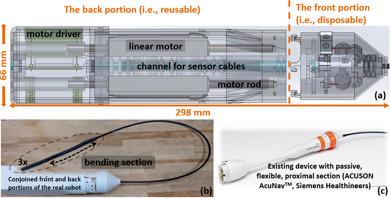
The existing manual device is shown in Fig. 1(c). This disposable catheter is actuated by hand by a physician; each knob connects to two opposing tendons and controls motion in one bending plane. Due to the structure of the handle, each knob can only pull one of its tendons at a time, depending on the direction of rotation, and a deadzone or area of slack can develop as the tendons stretch. The proposed device tackles the issue of reusability by introducing a separable mechanism and of deadzone by actuating all tendons. In short, the proposed device differs in that it is actuated, all four tendons can be manipulated independently, and it is separable to avoid disposing of the expensive electronics.
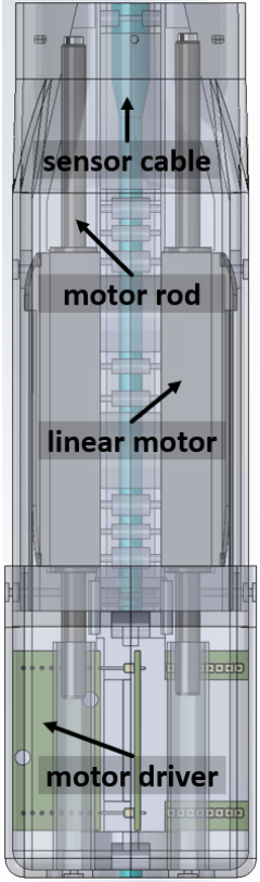
The proposed robotic system shown in Fig. 1 consists of two parts: the back portion or reusable portion contains four Faulhaber linear motors (LM 1483-080-11-C) with motor drivers mounted to a plastic core. The plastic core contains a channel along its central axis for an ultrasound (US) cable or for any other sensor cables, which is shown in blue in Fig. 1(a).
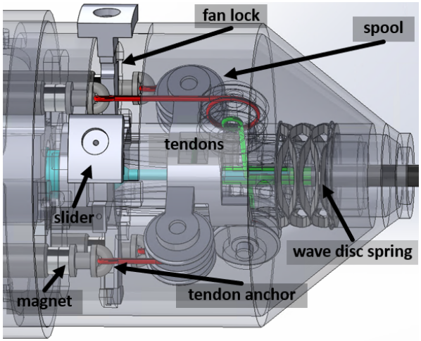
The front portion or disposable portion includes the tendons, the passive proximal section, and the articulation section, all of which are taken from an existing catheter as shown in Fig. 1(c). The interface from one tendon in the disposable portion shown in Fig. 2 to its respective linear motor is as follows: 1) the tendon (green) from the catheter is bent 90 degrees around a low-friction roller and is wrapped around and fastened to the small radius of the spool, 2) a separate tendon (red) is wrapped around and fastened to the large radius of the spool and then attached to the tendon anchor, and 3) the tendon anchor is held in place by the fan lock until the catheter is clipped together and the motor rod has connected to the tendon anchor via magnetic force. The fan lock is specially designed for this device and is so named because the “blades” of the fan are used to lock the tendon anchors in place until it is opened. The spools serve to increase the pulling force of the motors with a pulley ratio of :, where is the larger radius and is the smaller radius; and in our case the ratio is 3:1. The wave-disc spring serves to push the front portion against a locking mechanism consisting of plastic hooks in the back portion after the system has been clamped.
The proposed design has several advantages:
-
1)
Direct actuation of the tendons via linear motors facilitates a more transparent control input and gives a reliable measure of tendon tension via motor current. This prevents the need for additional tension sensors and reduces the complexity of hysteresis phenomena compared to [10], simplifying the control problem.
-
2)
The reusable portion contains no tendons, meaning that the issue of tendon wear present in many devices is avoided. The disposable portion (Fig. 2) can be unclipped and reclipped indefinitely, since the fan lock mechanism can clamp the tendons in place when the disposable portion is not attached and since the interface between the motor rods and the tendon anchors is magnetic (it does not involve a single use fastener).
-
3)
The clipping system has a closing mechanism similar to that of a child-proof medicine bottle: the front portion is pushed into the body until it makes contact, pushed slightly farther and twisted, then released. After releasing, the front is locked, the motors move their rods toward the front until their magnets make contact with the magnets on the tendon anchors, the sliders are pushed away from each other to manually open the fan-lock, and the motors are free to pull on the tendons.
3.2 Derivation of redundant control
3.2.1 Moment balance equation
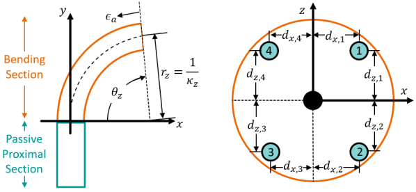
We borrow nomenclature from [43] and define the robot’s configuration for a compressible bending section as , where curvature about the x-axis [1/mm] corresponds to bending in the yz-plane, curvature about the z-axis [1/mm] corresponds to bending in the xy-plane, and axial strain [unitless] corresponds to compression along the y-axis. Just as in [43], curvature is chosen rather than bending angle for the configuration variables in q to obtain linear kinematic and static equations. First, we write the moment balance equation for a compressible bending section and tendons:
| (1) |
where the matrix K is a stiffness matrix containing [Nmm2], which is bending stiffness with respect to curvature , and [N], which is axial stiffness with respect to strain . The matrix D results from the cross product of the tendon locations [mm] with the tendon tensions [N] where . A conceptual side-view of the xy-plane and cross-section of the xz-plane are shown in Fig. 4.
If the bending section undergoes negligible compression, we can deviate from Eq. (1) and reduce the robot’s configuration to . The corresponding moment balance for an incompressible bending section is:
| (2) |
We can write Eq. (1) or Eq. (2) in matrix form:
| (3) |
The relation in Eq. (3) describes the static equilibrium, where the tendon tensions must balance against each other and the spring-like forces inherent to the bending of the catheter.
Let and . When , the system is redundant since there are more inputs than outputs . This means, for a given desired configuration , there are infinitely many solutions to Eq. (3). It is possible to solve this redundancy by minimizing the control effort via real-time optimization, but this will not necessarily solve the issue of slack tendons. We could include the constraint in the optimization, but we can develop a control scheme which resolves the redundancy and avoids real-time optimization. Derivation of the control scheme is handled for both the compressible and incompressible cases for completeness, although the results in this work will only use the incompressible case.
3.2.2 Compressible bending section (n=3, m=4)
Suppose we have four tendons located at 90 degree increments around the central axis of the beam. If the bending section is compressible, then we are using Eq. (1) and have three outputs. With one more input than output, we have one dimension of redundancy. Thus, the family of solutions for a given desired output can be parameterized along one vector, namely the vector which spans the nullspace of the map from the input to the output. We reorganize Eq. (1) and define , which is the map from the input to the output :
| (4) |
For a fully controllable system, , and the locations of the tendons in this system render it fully controllable (even if tendons can only pull, i.e., even if ). If we label the last tendon as redundant, we can partition C into a full rank portion B, which is square, and a redundant portion h, which is a column vector, as in [41]:
| (5) |
Given a desired output , the control input is:
| (6) |
where the desired output with a scalable parameter has no affect on the output. In other words, our family of solutions is parameterized by along the direction of the null space vector . The variable does not affect the output because n is in the null space of C:
| (7) |
The problems of redundancy and preventing tendon slack are solved with Eq. (6) and an appropriate choice of . An obvious choice for is the one that minimizes the control effort [44, 45] as follows:
| (8) | ||||
| s.t. |
where the constraints on (no slack) and the bottom row of Eq. (6) imply that . The choice of control input in Eq. (6) allows us to directly calculate instead of solving this optimization computationally. In the unconstrained case, the minimum is found as follows:
| (9) |
If the solution to Eq. (9) does not violate the constraints in Eq. (8), then that minimum is sufficient. If it does violate those constraints, then we simply pick the smallest which satisfies all of the constraints. To highlight, let the rows of be denoted by where such that . Then we can write the constraints from Eq. (8) for tension in each tendon:
| (10) |
where we can see that every term in the equations except for is determined by the structure of the robot ( and h) and the desired configuration (). The strength of this controller is that, as long as the structure of the robot in C does not vary explicitly with configuration or time, we can choose a constant value for and achieve a control input for any desired state without real-time optimization.
We elaborate on the previous statement and note the limitations of the analysis so far. In our case, the choice of redundant tendon and thus the redundant column of C was arbitrary; we could choose any tendon and get the same result. This is because the locations of the tendons relative to the central axis do not depend on the system configuration, which means B is independent from the input. In other robots [41], it is possible for B to become ill-conditioned with changing configuration, in which case an algorithm is required to ensure an appropriate tendon is chosen. The final step is to derive the kinematics, but first the case for an incompressible articulation section–which is more relevant in this work–must be derived.
3.2.3 Incompressible bending section (n=2, m=4)
In this case, the compression of the bending section is negligible compared to the magnitude of bending. Therefore, we can use Eq. (2) and will have two outputs. This results in two dimensions of redundancy and a family of solutions which can be parameterized by two scalars, and , along the directions of two vectors, and , which span the null space of C. We arbitrarily label the last two tendons as redundant and partition C into a full rank portion B, which is square, and two redundant portions and , which are both column vectors. For a given desired output , the control input as follows:
| (11) |
where and are the desired output with two scalable parameters. As before, adjusting or has no affect on the output since and lie in the null space of C:
| (12) | |||
If the tendons are located equidistant from each other about the central axis, the assumption of incompressibility decouples the bending caused by one pair of tendons (1 and 3) from the bending caused by the other pair of tendons (2 and 4). In other words, and , which means and do not appear in the same tension equation. Thus, the minimum and can be determined independently, in a procedure similar to the compressible case via Eq. (8) and Eq. (9). If we denote the rows of B by such that , we can write as follows:
| (13) |
where and are the only unknowns and can be chosen independently. Again we see that we need only pick and to obtain feasible tensions without real-time optimization. For a minimum allowable tension of (i.e., no slack condition), , but the constraint is generally not strict enough to ensure that no slack occurs. Therefore, small constants should be found experimentally for and to ensure a low pre-tension which prevents slack tendons. Why this is referred to as ”pre-tension” will be addressed in the discussion. With and discussed, we move on to the kinematics and summarize the procedure for determining the control input.
3.2.4 Kinematics
The preceding discussion yielded the force input (tendon tensions) for the system. However, it is often preferred to command actuator positions (tendon displacements). To convert the input from forces to positions y, we consider the conservation of strain equation [43]:
| (14) |
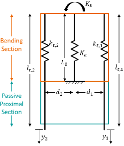
where , , and are diagonal matrices containing the undeformed bending section length , the unstretched tendon lengths , and the length-normalized tendon stiffnesses , respectively. For instance, tendon 1 would have unstretched length located in row 1 and column 1 of . The moment balance in Eq. (3) along with Eq. (14) define a planar spring model in which the moments and forces exerted by the tendons balance against the inherent bending and axial stiffness of the articulation section. An example for a two-tendon planar spring model is given in Fig. 5.
Using Eq. (3) we can finally obtain a direct relation between y and :
| (15) |
If the actuators pulled the tendons directly, Eq. (15) would be sufficient. Since our system uses pulleys to increase the effective pulling force of the actuators, we have additional steps. The force felt by the motors is given by:
| (16) |
where R is a diagonal matrix containing the pulley ratio.
Then, the displacement of the motors , which depends on the displacement of the catheter tendons y and the deflection of the additional tendons due to the motor force , is as follows:
| (17) |
where is a diagonal matrix containing the undeformed lengths of the additional tendons , which are shown in red in Fig. 2. Substituting Eq. (15) into Eq. (17) yields:
| (18) |
and replacing with using Eq. (16), we can rewrite Eq. (17) in terms of the displacement of the actuators and forces felt by the actuators :
| (19) |
Now that we have Eq. (19), the process of determining the control input can be summarized.
3.2.5 Redundant control summary
The scalars and are found experimentally and are chosen such that tendons remain in tension. Since these values can effect parameter estimates, it is best to leave them constant once they are chosen. Given and , the tendon tensions in which correspond to the desired configuration are computed using Eq. (6) or Eq. (11), depending on whether the manipulator is compressible. The tensions in are converted into tendon displacements in using Eq. (15). This method gives a single vector y for any desired configuration , resolving the redundancy while preventing slack tendons. The redundant control input is considered the baseline input for the remainder of this work.
Prior works have included as a constraint in an optimization which solves for minimum in cable-driven platform [41] and dexterous hand applications [42]. Camarillo et al. [43] developed an algorithm which optimizes while allowing slack tendons (as long as they contribute no force) for a continuum manipulator. We differ from these works in that we leverage the structure of the constant curvature kinematics to get an analytical solution and avoid real-time optimization altogether. We also differ from [43] since our method does not permit slack tendons. With the baseline control input established, we move on to the compensation methods.
3.3 Practical Compensation methods
3.3.1 Preliminaries: Time-shift and DC Offset
Before introducing the compensation methods, we must mention the two phenomena which they will compensate.
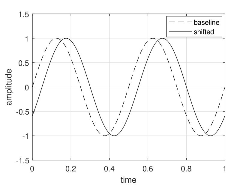

Hysteresis is defined as the phenomenon in which the value of a physical property lags behind changes in the effect causing it. In the presence of unmodeled hysteresis, an output will tend to lag an input in an open-loop system each time the direction of the input changes, due to friction induced backlash from the hysteresis. For a periodic input, this lag manifests as an obvious phase lag or time-shift as idealized in Fig. 6(a). We hypothesize that hysteresis compensation can reduce this phenomena and thereby reduce error. Bending of the passive proximal section will naturally occur during operation of such flexible-steerable devices, for instance in traversing blood vessels to reach the heart in catheter applications, and this behavior is typically unmodeled. We found that introducing an angle in the proximal section in one direction causes the articulation section to bend in the other direction, as visible when comparing Fig. 8(a) with 8(b). We guess that this is caused by the increased stretching and thus increased tension in the outer tendon(s) and decreased tension in the inner tendon(s). This change in tensions causes an offset of the unbent configuration of the articulation section, which results in an offset of the output. For a sinusoidal input in the same plane as the proximal section deformation, the offset in the output would manifest as a DC offset of the sinusoid as shown in Fig. 6(b).
We further predict that these two sources of error are, for the most part, independent. For a sinusoidal input with amplitude and frequency , we would expect the output to be shifted in time due to hysteresis by some amount and offset due to the passive proximal section angle by some amount , as follows:
| (20) |
3.3.2 Simple hysteresis compensation for time-shift
The design of the robot and the control scheme result in a hysteresis curve, shown in Fig. 7, which is very linear and has approximately no deadzone. The simplicity of this hysteresis curve allows us to implement a simplified hysteresis compensation on top of the control scheme which does not rely on extra sensors or tuning a large number of parameters; however, those methods are compatible with the control scheme and could still be implemented in future works.
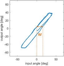
The simple hysteresis compensation consists of a constant value added to the desired input depending on the direction of motion. This constant value is based on the width of the hysteresis curve, also shown in Fig. 7, which can be determined from the input-output map of a continuum manipulator and is device dependent. The input and output are given as angles in degrees since bending angle is easier to conceptualize than curvature, and the compensation equation is also given as an angle:
| (21) |
This desired angle with hysteresis compensation is converted into a desired curvature using the usual equation for constant curvature in the incompressible case:
| (22) |
This additional compensation involves an adjustment of the input configuration in order to achieve the configuration which is truly desired, and thus it completely compatible with the previously described control scheme.
3.3.3 Re-tension compensation for DC offset
The re-tension compensation aims to remove error introduced by the passive proximal section angle, which manifests as a DC offset for a sinusoidal input. This angle can come about naturally in medical applications, such as in the tortuous path of a catheter from the incision point to the heart. In the baseline case, the robot is initialized, and the passive proximal section angle is introduced with no movement of the actuators. That is, the motors are powered and holding their positions under the assumption that the proximal section is straight. This is not unreasonable, as current kinematic and dynamic representations of continuum robots with bending sections make the assumption that the passive proximal section is straight. In the case with re-tension compensation, the robot is given approximately 3-5 seconds to re-tension the tendons to the desired pre-tension (0.25 N) after the passive proximal section angle has been introduced but before data for the sinusoidal input is collected. Motor current is filtered using a order Butterworth filter to remove high frequency noise, and this filtered motor current is used along with the force constant from the manufacturer to get a measure of motor force and thus of tendon tension. It is anticipated that re-tensioning the tendons will remove some of the error from the passive proximal section angle.
4 Experiments and Results
4.1 Equipment and setup
The experimental setup is shown in Fig. 8.
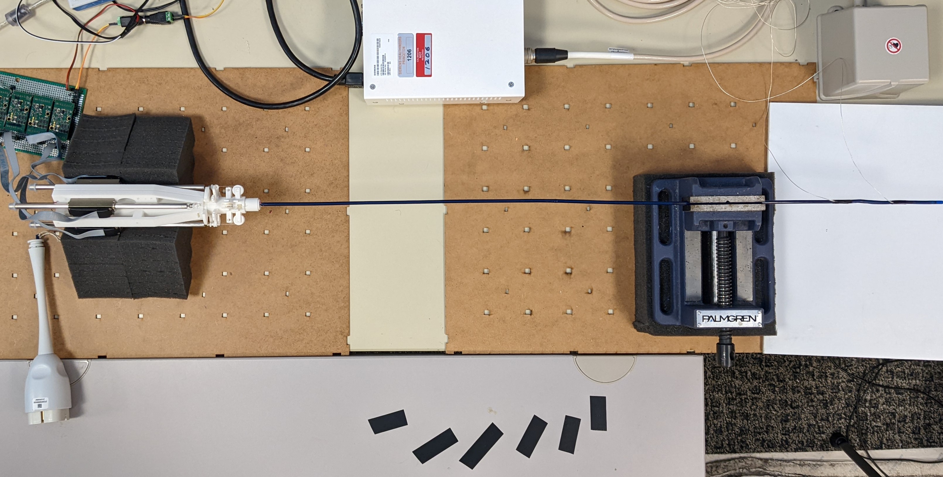
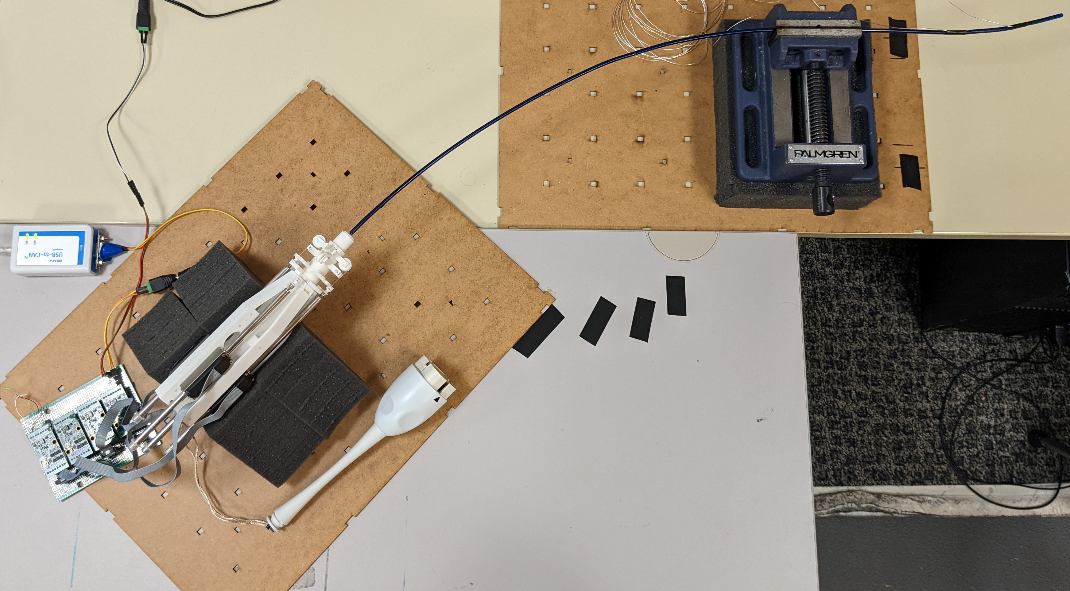
The prototype was laid on a table, and the proximal section was lightly clamped just proximal to the bending section using a vise. A protractor was used to measure the angles for the catheter body, and tape was used to mark the locations on the table. Special care was taken to keep the curve of the proximal section tangent to the axis of the catheter body and of the vise at all angles. Bending angle was measured using an EM sensor (3D Guidance trakSTAR 2) for validation purposes only, meaning that the EM measurement was not used in the control loop and that the control was performed entirely using the kinematics.
4.2 Parameter identification
Since compression of our articulation section is negligible, we use the equations and associated parameters for an incompressible device. All parameters in the equations must be determined empirically. , , , R, and can be measured directly. and are determined heuristically; they are chosen as the smallest constants which result in no slack tendons–as measured from motor current–for a few test inputs. K and D can be approximated by the following parameter identification procedure:
-
1.
Make initial guess for parameters.
-
2.
Input motor position trajectories which should achieve desired bending angle as calculated from inverse kinematics and redundant control input.
-
3.
Update parameter guesses based on difference between desired and measured bending angle.
-
4.
Repeat steps 2 and 3 until parameter values converge.
This procedure is also rather heuristic, but it achieved consistent values for K and D with a bisection search. Parameter values are listed in Table 1.
| Parameter | Value | Resolution | Units |
|---|---|---|---|
| (0.492, -0.0868) | 0.00625 | mm | |
| (0.0868, 0.492) | 0.00625 | mm | |
| (-0.492, 0.0868) | 0.00625 | mm | |
| (-0.0868, -0.492) | 0.00625 | mm | |
| 360.0 | 3.125 | Nmm2 | |
| 1080 | 5.0 | N | |
| 60 | 0.5 | mm | |
| 20 | 0.5 | mm | |
| 25 | 0.5 | mm | |
| 20 | 0.5 | mm | |
| 30 | 0.5 | mm | |
| 775 | 0.5 | mm | |
| 785 | 0.5 | mm | |
| 775 | 0.5 | mm | |
| 785 | 0.5 | mm | |
| 3.0 | 0.1 | unitless | |
| 0.25 | N/A | unitless | |
| 0.25 | N/A | unitless |
The tendon locations , as seen in Fig. 4, are given as coordinates . For simplicity, the tendon locations were assumed to be at 90∘ increments around the central axis, but this assumption is not necessary to complete the parameter identification. For values which were not measured (i.e., and ), resolution refers to the smallest step of the bisection used to identify the value.
4.3 Experiments
The robot was tested under three scenarios of validation which are listed here in brief and explained in detail in the subsections to follow.
-
1.
Straight Condition – sinusoidal input; no passive proximal section angle; baseline and hysteresis compensation
-
2.
Curved Condition – sinusoidal input; passive proximal section angles; baseline, re-tension, hysteresis, and re-tension + hysteresis (both) compensation
-
3.
Dynamic Condition – re-tension compensation is tested while changing passive proximal section angle
4.3.1 First Scenario: Straight Condition
The first scenario tests the robot and the redundant controller under the default condition of a straight passive proximal section. The proposed controller was validated with three trials on a test bed by following a desired sinusoidal input for bending angle in one dimension. For each trial, the robot followed two cycles of the sinusoid, and the ground truth output angle was measured with an EM sensor, which was only used to evaluate performance. Tip position and bending angle errors were described as mean absolute error (MAE) and standard deviation (StD). Performance was evaluated without and with simple hysteresis compensation. The simple hysteresis compensation involved adjusting the input angle by a constant 10 degrees depending on the direction of motion as described in Eq. (21). The backlash width or width of the hysteresis curve () was obtained based on the unique physical properties of the catheter [10].
4.3.2 Second Scenario: Curved Condition
We hypothesized that the shape of the passive proximal section affects the accuracy of the kinematics by altering the tensions in the tendons and that any increase in error would be caused by these changes tension. We implemented two types of compensation–one targeted at hysteresis and the other targeted at pre-tension errors caused by the passive proximal section angle–and hypothesized that these are two separate sources of error that would both require compensation. Data were collected using a test-bed of the prototype under various conditions for two periods of a sinusoidal input with an amplitude of 45∘ and a frequency of 0.1 Hz. Note that the input refers to bending angle, which is then converted to curvature for use in the kinematics. For baseline and re-tension compensation, trials were gathered for six passive proximal section angles (15, 30, 45, 60, 75, and 90 degrees) and two bending planes (xy and yz). For hysteresis compensation and re-tension + hysteresis compensation, trials were gathered for three passive proximal section angles (30, 60, and 90 degrees) and two bending planes (xy and yz). Two bending planes are tested to confirm that error introduced by the passive proximal section angle is independent of the input plane.
4.3.3 Third Scenario: Dynamic Condition
In the previous cases, the re-tension compensation involved giving the robot a few seconds to recover the desired minimum tensions, which was followed by a desired input trajectory; in this case, the controller attempts to maintain the desired minimum tensions for all 30 seconds of each trial, and there is no trajectory input (only the re-tension compensation). The robot is moved manually for approximately 20 seconds to change the passive proximal section angle from 0 to 60 degrees and then allowed to settle for an additional 10 seconds. Data were collected for three trials, both without and with re-tension compensation. It was expected that a large mismatch between the measured angle and the desired angle of 0 degrees would develop without re-tension compensation.
4.4 Results
4.4.1 First Scenario: Straight Condition Results
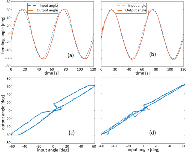
Fig. 9 shows bending angle without and with the simple hysteresis compensation. The control of all tendons simultaneously allowed the removal of tendon slack and thereby deadzone present in conventional catheters. The overall performance evaluation is described in Table 2. The tip pose error (MAE) is reported as . With hysteresis compensation, the position and orientation errors are improved and , respectively.
| Angle | Compensation | Error StDev | % Reduction |
|---|---|---|---|
| 0∘ | baseline | 6.11∘ 4.03∘ | N/A |
| hysteresis | 3.26∘ 2.90∘ | 46.6 |
Bending angle error is reduced by including the simple hysteresis compensation. We also see from Fig. 9c and 9d that hysteresis is reduced noticeably even with simple compensation.
4.4.2 Second Scenario: Curved Condition Results
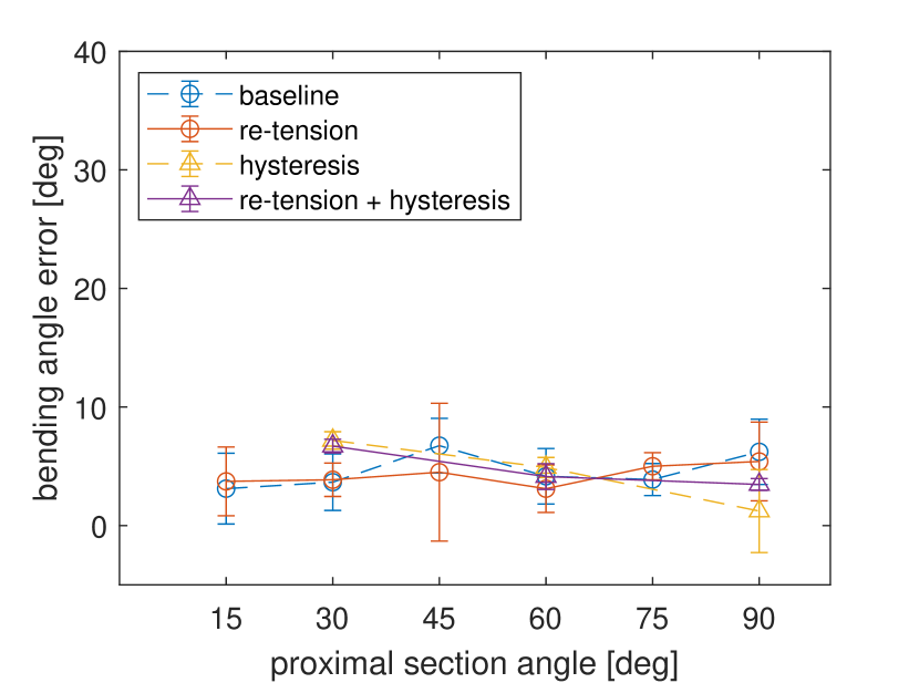
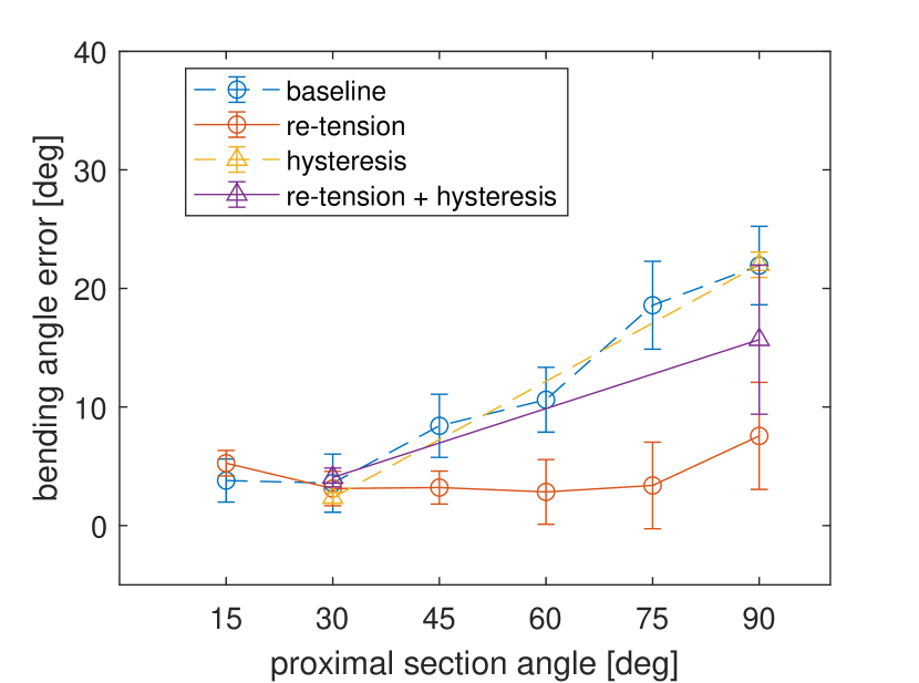
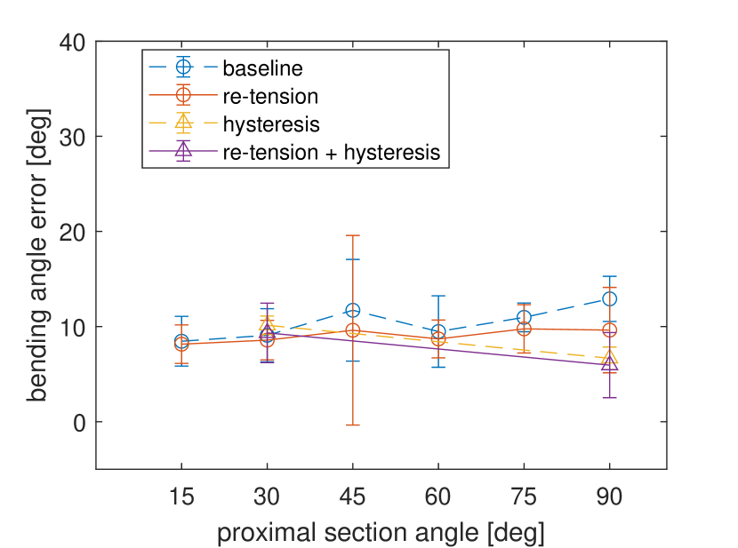
Until otherwise stated, the following plots and tables for the second scenario involve an input in the xy-plane. For the xy-plane input, bending occurs in the same plane as the passive proximal section angle, since the passive proximal section angle is created by moving the body to the right. Error bars denote the standard deviation over the three trials at that data point. Fig. 10 shows bending angle error for the six proximal section angles and four compensation types in the xy-plane and yz-plane, respectively.
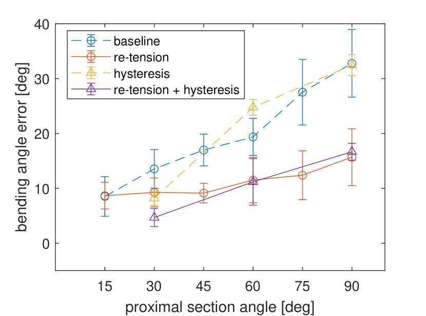
From Fig. 10(a) it is clear that bending angle error in the xy-plane increases with increasing proximal section angle for all compensation types; however, both compensations with re-tension were less susceptible to this error increase. Error in the yz-plane is unaffected because the passive proximal section is bent in the xy-plane. The error values (RMSE), standard deviations, and percent reduction in error relative to the baseline case are given in Table 3, and the averages for the proximal section angles with all compensation types are in Table 4.
| Angle | Compensation | Error StDev | % Reduction |
| 15∘ | baseline | 8.52∘ 3.62∘ | N/A |
| re-tension | 8.66∘ 2.43∘ | -1.62 | |
| hysteresis | – | – | |
| both | – | – | |
| 30∘ | baseline | 13.54∘ 3.52∘ | N/A |
| re-tension | 9.26∘ 2.64∘ | 31.64 | |
| hysteresis | 8.17∘ 1.23∘ | 39.66 | |
| both | 4.66∘ 1.65∘ | 65.55 | |
| 45∘ | baseline | 16.98∘ 2.90∘ | N/A |
| re-tension | 9.12∘ 1.79∘ | 46.28 | |
| hysteresis | – | – | |
| both | – | – | |
| 60∘ | baseline | 19.37∘ 3.38∘ | N/A |
| re-tension | 11.50∘ 4.14∘ | 40.62 | |
| hysteresis | 24.76∘ 1.43∘ | -27.86 | |
| both | 11.17∘ 4.25∘ | 42.31 | |
| 75∘ | baseline | 27.53∘ 5.98∘ | N/A |
| re-tension | 12.39∘ 4.45∘ | 55.00 | |
| hysteresis | – | – | |
| both | – | – | |
| 90∘ | baseline | 32.79∘ 6.17∘ | N/A |
| re-tension | 15.68∘ 5.18∘ | 52.19 | |
| hysteresis | 32.45∘ 1.91∘ | 1.03 | |
| both | 16.66∘ 1.54∘ | 49.19 |
| Compensation | Error StDev | % Reduction |
|---|---|---|
| baseline | 21.90∘ 4.36∘ | N/A |
| re-tension | 12.15∘ 3.99∘ | 41.48 |
| hysteresis | 21.79∘ 2.48∘ | 4.28 |
| both | 10.83∘ 1.54∘ | 52.35 |
To give a closer look at how error increases with proximal section angle, bending angle for 30, 60, and 90 degrees is shown in Fig. 11, where shaded regions denote the standard deviation of the trajectory.
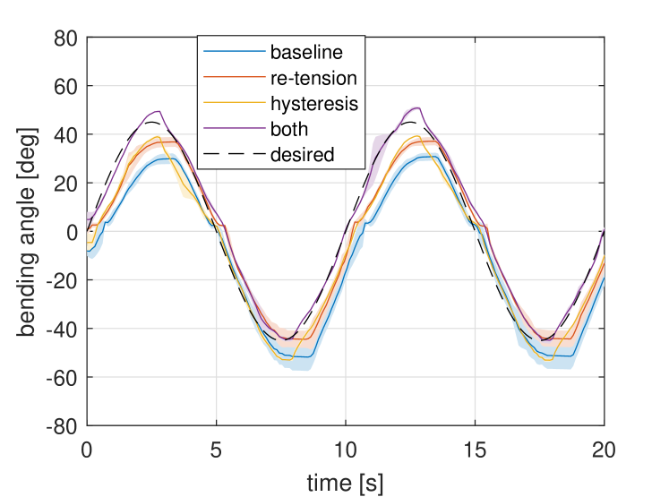

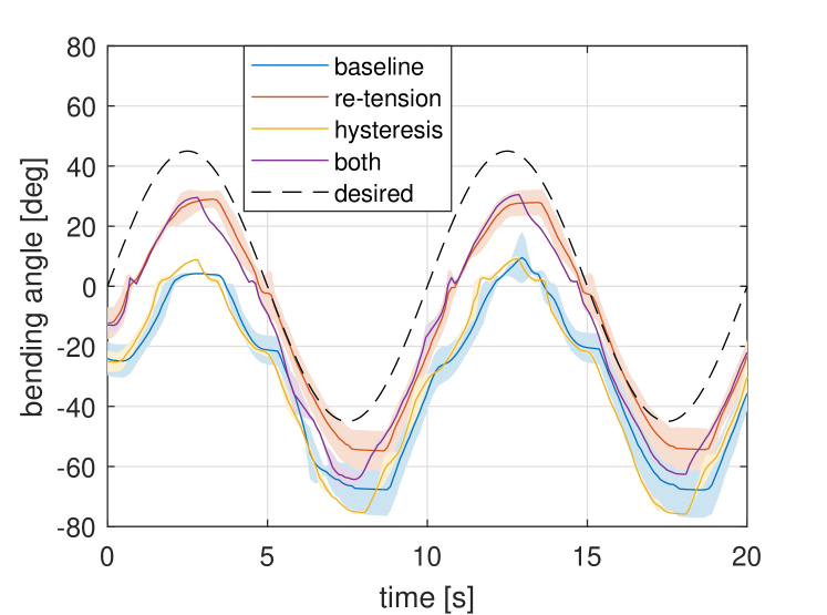
Going from Fig. 11(a) to 11(b) and from Fig. 11(b) to 11(c), the source of the increasing error becomes more obvious: increases in passive proximal section angle caused an increase in the offset or bias error of the catheter tip. This phenomenon was visible in the bending section during experimentation, and can be seen when comparing the tip in Fig. 8(a) to the tip in Fig. 8(b). Also of note, the quality of the output angle degrades as the offset increases; this can be seen by examining the baseline or hysteresis compensated angle as the offset gets large and may be due to increased friction in the tendon sheath mechanism.
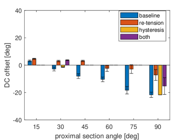
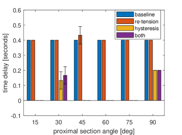
To better show how the re-tension and hysteresis compensation reduce error from different sources, we examine the DC offset and the time delay of the bending angle in Fig. 12 and Fig. 13, respectively. Time delay was computed by filtering the output (low pass, cutoff 2 Hz) and finding the cross-correlation between each output and the input. DC offset is the distance of the mean of each filtered output from zero.
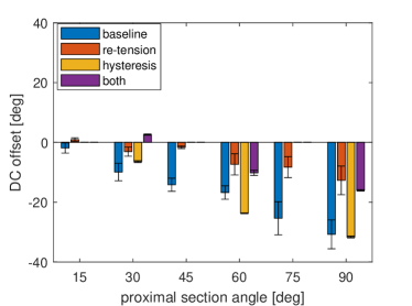
The increasing DC offset for increasing proximal section angle in Fig. 13 reflects the increasing error seen in Fig. 10(a). It also mirrors Fig. 10(a) in that the re-tension and re-tension + hysteresis compensation trials are less affected by the offset, just as these compensations both had lower error for increasing proximal section angle. This suggests that this offset caused by the passive proximal section angle is the primary source of error.
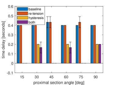
From Fig. 13, it is clear that the simple hysteresis compensation reduces the time delay from hysteresis by half. However, Fig. 10(a) shows that the reduction in hysteresis does not reduce the error substantially for increasing proximal section angle, relative to the error reduction from the re-tension compensation. This furthers the idea that the DC offset is the larger source of error, especially at higher proximal section angles, and that the effect of the proximal section angle on the bending section should not be ignored.
The remaining figures for scenario two involve an input in the yz-plane. For the yz-plane input, bending occurs perpendicular to the plane in which the passive proximal section is bent. Fig. 14 shows that the error in the xy-plane still increases with proximal section angle, even though the input is in the yz-plane. The trials with re-tension compensation still exhibit less error for increasing proximal section angle as well. Trials including hysteresis compensation were only collected at the extremes, namely 30 and 90 degrees.
We again see the trend on increasing error in the xy-plane reflected in the DC offset of the output in the xy-plane in Fig. 15, although it is less pronounced than in the xy-input case.
The trials with re-tension compensation have lower offset at 90 degrees compared to those without, but it is difficult to say for certain whether the overall trend from the xy-input case is preserved with the lower offset numbers and missing 60 degree hysteresis data. Fig. 16 shows that the hysteresis compensation reduced the time delay by half as expected from the xy-input case.
4.4.3 Third Scenario: Dynamic Condition Results
The effect of introducing the passive proximal section angle in a dynamic scenario is shown in Fig. 17.
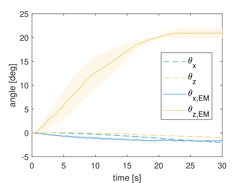
The bending angle in the xy-plane according to the kinematics and the EM sensor is denoted by and respectively; and the bending angle in the yz-plane according to the kinematics and the EM sensor is denoted by and , respectively. If the passive proximal section angle had no effect on the kinematics, we would expect to see and both remain close to 0 for the duration of the trial in Fig. 17(a). However, in Fig. 17(a) we instead see the consequence of increasing the passive proximal section angle from 0 to 60 degrees in the xy-plane without compensation is that the measured angle accumulates over 20 degrees of offset from 0. This agrees closely with the mean error for the baseline trial in the static case in Fig. 10(a), further supporting that most of the error in the static case comes from this offset error. We also see that this behavior is not captured well by the kinematics, since and only deviate by a few degrees.
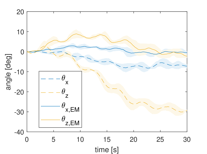
If the control gains are increased, the trajectory will be held closer to 0, but the oscillations will increase. Table 5 gives the measured error in the configuration–in this case deviation from the starting configuration (0,0) by the end of the trial–along with the reduction in error due to the re-tension compensation.
| Angle | Compensation | Error StDev | % Reduction |
|---|---|---|---|
| baseline | -1.69∘ 0.12∘ | N/A | |
| re-tension | -0.47∘ 0.82∘ | 72.29 | |
| baseline | 20.94∘ 1.09∘ | N/A | |
| re-tension | -2.27∘ 0.89∘ | 89.14 |
5 Discussion
The design of the robot allowed for the implementation of the redundant controller and additional compensation methods. The current actuators are not strong enough to exceed the breaking force of the magnets, but if more powerful actuators were used, this could become an issue. A good addition to the design to overcome this would be a rail structure which contains the tendon anchors without obstructing the tendons, allowing the motors to reestablish contact with the tendon anchors after a disconnect.
Although the robot is separable, the control input, compensation methods, and results are applicable to most tendon-driven manipulators with a passive proximal section; and it is unlikely that the separable nature of the device introduced any appreciable error. On a similar note, the robot in this work experienced negligible compression, and thus only the equations for an incompressible bending section were used. That said, the controller does not depend on the assumption of incompressibility, and the relevant equations which were presented can be used for a compressible robot. The parameter identification made the practical assumption that the tendons are located at 90 degree increments in order to keep the process simple enough for a small number of sensors. This simplification is not necessary to use the presented kinematics–the D matrix does not naturally assume 90 degree angles–and relaxing this assumption could yield higher tip position accuracy. However, in order to relax this assumption, more sensor information would likely be required during the parameter identification.
A redundant control scheme was used with the constant curvature assumption to resolve and take advantage of this redundancy, in which the control effort is minimized while respecting feasibility constraints (such as requiring a minimum tension for all tendons) as in [41] but with two key differences. The first difference is that the minimum is easily found analytically since is the only unknown, and so there is no need to optimize in real-time. The second difference is that the axial positions of the tendons do not change appreciably during actuation, meaning that we will not encounter a singular configuration and will not need to reconstruct B as in [41].
During the procedure for determining and in the methods section, we referred to these values as “pre-tension”. This is because mathematical redundancy in real systems often points to a physical phenomenon, in this case the magnitude of pre-tension or co-contraction of opposing tendons. If we assume the four tendons are at 90 degree increments and incompressibility, the redundancy represents the co-contraction or simultaneous pulling of opposing tendons, such as tendons 1 and 3, just as opposing tendons are pulled in muscle contractions. Furthermore, the magnitude of this co-contraction is determined by and . In theory, and could be any positive value without affecting the configuration of the manipulator. In practice, large values of or could cause compression of the “incompressible” bending section, buckling of the passive proximal section, and changes in the stiffness estimates. Thus, it is best to use small values of and as a method for preventing slack tendons in that any or value above zero effectively enforces a pre-tension in the corresponding tendons equal to the magnitude of or . We also suggested keeping the scalable redundant parameters and constant to avoid affecting other parameter estimates such as bending stiffness. There is room for future experimentation in which these parameters are intentionally varied in order to obtain variable stiffness behavior, akin to impedance control.
The deflection of the passive proximal section to the right caused an offset of the bending section to the left, irrespective of the plane of the input. This offset was the primary source of bending angle error and increased with increasing passive proximal section deflection. Simple hysteresis compensation alone did not substantially reduce bending angle error, although it did reduce the phase lag of the output. Re-tension compensation reduced DC offset and bending angle error, both alone and with hysteresis compensation. Compensation methods were kept simple so that the sources of error were not obscured and so that they can be implemented in the absence of a tip sensor; however, there is room for future work involving more complex re-tension or hysteresis compensations, perhaps relying on additional sensors.
The trials with re-tension compensation had reduced error at all angles relative to trials without. By adjusting the tendon tensions to their minimum values, the compensation can be seen as getting much closer to a neutral, unstretched state which the proximal section is assumed to have by kinematic models in the state of the art. However, even for trials with re-tension compensation, error still increases for increasing proximal section angle. This is likely because, even with the tendon tensions adjusted, the proximal section is still deformed, deforming the tendon sheaths and the outer casing of the proximal section and articulation section. These deformations are not fully compensated by the re-tension compensation and should be investigated in future works.
The amount of time the re-tension compensation was given to reach the desired tension was arbitrary. Since the re-tension occurs before the trial in the second scenario, the time spent re-tensioning does not affect the controller during the trial. This compensation is useful for any application where the proximal shape will remain unchanged for a long period of time, such as after insertion of a heart catheter. For the dynamic case in the third scenario, the re-tension occurs while the proximal section shape is changing. This type of compensation would be useful for applications where the shape is changing over time, such as during insertion of a catheter.
The trials with hysteresis compensation tended to have lower error than those without for the lower proximal section angles, and the same or slightly higher error for the higher angles. That hysteresis compensation is less helpful at higher angles is unsurprising, as we would expect errors from the proximal section angle to be the dominant source of error at higher angles. It is a little surprising that hysteresis compensation would cause a slight increase in error at some of the higher angles, and this would suggest that the two sources of error, proximal section angle and hysteresis, are not entirely decoupled. That said, the data presented regarding DC offset and time-shift and the fact the error increase is small both suggest that the phenomena are mostly independent.
The amount of hysteresis compensation was based on the width of the hysteresis curve. This curve was relatively constant for different input amplitudes, but there is room for future work in augmenting this simple hysteresis compensation by varying the magnitude slightly based on the input amplitude or some other factor.
The passive proximal section angle affects the accuracy of the kinematics, and the magnitude of this effect should not be ignored. How it is included depends on whether a sensor is present at the tip of the continuum manipulator. With a tip sensor for closed-loop control, the deviation between the desired output and the measured output can be used to update the kinematics or dynamics to account for the proximal section angle, whether it updates the system parameters directly or simply adds an additional term to the equations. Without a tip sensor there is no way to update the kinematics or dynamics real-time without first measuring the behavior for different passive proximal section angles off-line, and so they should be adjusted off-line based on the behavior of the system at different expected configurations.
A strength of this study is that a one-dimensional angle in the passive proximal section causes a clear one-dimensional change in the bending section, but this is also its limitation. The effect of multiple bends in different directions, such as two bends in an S-shaped curve, of the passive proximal section should be investigated in future work, though the relationship between the passive proximal section shape and the bending section may not be as simple to characterize.
6 Conclusion
We introduced a separable tendon-driven robot manipulator which addresses practical issues in actuation and sterilization. The separable design allows for reuse of all electromechanical components and does not use tendons in the reusable portion, avoiding mechanical wear. The interface between the actuators and the tendons is very transparent and all tendons are actuated, allowing for mitigation of backlash and deadzone. The fan-lock and magnetic interface allow for un-clipping and re-clipping.
We presented a control scheme which utilizes the simplicity of constant curvature to yield a single solution to the inverse kinematics without the need for real-time optimization. The control scheme can be used without a tip sensor and does not require high fidelity knowledge of system parameters a priori, which is frequently lacking for mass-produced medical devices.
The control scheme was validated along with additional re-tension compensation for proximal section angle and hysteresis compensation. On average, error was reduced by 41.48% for re-tension, 4.28% for hysteresis, and 52.35% for re-tension + hysteresis compensation relative to the baseline case. The re-tension compensation was tested for dynamic changes in the proximal section. The error in the final configuration of the tip was reduced by 89.14% relative to the baseline case
7 Disclaimer
The concepts and information presented in this paper are based on research results that are not commercially available. Future availability cannot be guaranteed.
8 Acknowledgement
Research reported in this publication was supported in part by the National Institute of Biomedical Imaging and Bioengineering of the National Institutes of Health under award number R01EB028278. The content is solely the responsibility of the authors and does not necessarily represent the official views of the National Institutes of Health.
References
- [1] Stereotaxis, 2020, Stereotaxis v-drive robotic navigation system, Feb. http://www.stereotaxis.com/products/vdrive.
- [2] Kim, Y.-H., Collins, J., Li, Z., Chinnadurai, P., Kapoor, A., Lin, C. H., and Mansi, T., 2022, “Automated catheter tip repositioning for intra-cardiac echocardiography,” International Journal of Computer Assisted Radiology and Surgery, 17, p. 1409–1417.
- [3] Reddy, MD, V. Y., Neuzil, MD, P., Malchano, BS, Z. J., Vijaykumar, BS, R., Cury, MD, R., Abbara, MD, S., Weichet, MD, J., McPherson, BS, C. D., and Ruskin, MD, J. N., 2007, “View-Synchronized Robotic Image-Guided Therapy for Atrial Fibrillation Ablation,” Circulation, 115(21), May, pp. 2705–2714.
- [4] Agrawal, A., Hogarth, D. K., and Murgu, S., 2020, “Robotic bronchoscopy for pulmonary lesions: a review of existing technologies and clinical data,” Journal of Thoracic Disease, 12(6), June, pp. 3279–3286.
- [5] Intuitive Surgical, 2022, Ion platform - robotic-assisted bronchoscopy https://www.intuitive.com/en-us/products-and-services/ion.
- [6] Johnson & Johnson , 2022, Monarch platform https://www.jnjmedtech.com/en-US/product/monarch-bronchoscopy.
- [7] Dupont, P. E., Simaan, N., Choset, H., and Rucker, C., 2022, “Continuum Robots for Medical Interventions,” Proceedings of the IEEE, 110(7), July, pp. 847–870.
- [8] Zhang, T., Ping, Z., and Zuo, S., 2021, “Miniature Continuum Manipulator With Three Degrees-of-Freedom Force Sensing for Retinal Microsurgery,” Journal of Mechanisms and Robotics, 13(4), Apr.
- [9] Cao, Y., Feng, F., Liu, Z., and Xie, L., 2022, “Closed-Loop Trajectory Tracking Control of a Cable-Driven Continuum Robot With Integrated Draw Tower Grating Sensor Feedback,” Journal of Mechanisms and Robotics, 14(6), Sept.
- [10] Lee, D.-H., Kim, Y.-H., Collins, J., Kapoor, A., Kwon, D.-S., and Mansi, T., 2021, “Non-linear hysteresis compensation of a tendon-sheath-driven robotic manipulator using motor current,” IEEE Robotics and Automation Letters, 6(2), pp. 1224–1231.
- [11] Daoud, E. G., Kalbfletsch, S. J., and Hummel, J. D., 1999, “Intracardiac Echocardiography to Guide Transseptal Left Heart Catheterization for Radiofrequency Catheter Ablation,” Journal of Cardiovascular Electrophysiology, 10(3), Mar., pp. 358–363.
- [12] Khoshnam, M., Khalaji, I., and Patel, R. V., 2015, “A robotics-assisted catheter manipulation system for cardiac ablation with real-time force estimation,” In 2015 IEEE/RSJ International Conference on Intelligent Robots and Systems (IROS), pp. 3202–3207.
- [13] Khoshnam, M., and Patel, R. V., 2017, “Robotics-Assisted Control of Steerable Ablation Catheters Based on the Analysis of Tendon-Sheath Transmission Mechanisms,” IEEE/ASME Transactions on Mechatronics, 22(3), June, pp. 1473–1484.
- [14] Bai, R., Di Biase, L., Valderrabano, M., Lorgat, F., Mlcochova, H., Tilz, R., Meyerfeldt, U., Hranitzky, P. M., Wazni, O., Kanagaratnam, P., Doshi, R. N., Gibson, D., Pisapia, A., Mohanty, P., Saliba, W., Ouyang, F., Kautzner, J., Gallinghouse, G. J., and Natale, A., 2012, “Worldwide Experience with the Robotic Navigation System in Catheter Ablation of Atrial Fibrillation: Methodology, Efficacy and Safety,” Journal of Cardiovascular Electrophysiology, 23(8), pp. 820–826.
- [15] Khan, E. M., Frumkin, W., Ng, G. A., Neelagaru, S., Abi-Samra, F. M., Lee, J., Giudici, M., Gohn, D., Winkle, R. A., Sussman, J., Knight, B. P., Berman, A., and Calkins, H., 2013, “First experience with a novel robotic remote catheter system: Amigo™ mapping trial,” Journal of Interventional Cardiac Electrophysiology, 37(2), Aug., pp. 121–129.
- [16] Hasanzadeh, S., and Janabi-Sharifi, F., 2014, “An Efficient Static Analysis of Continuum Robots,” Journal of Mechanisms and Robotics, 6(3), Apr.
- [17] Ott, L., Nageotte, F., Zanne, P., and de Mathelin, M., 2011, “Robotic Assistance to Flexible Endoscopy by Physiological-Motion Tracking,” IEEE Transactions on Robotics, 27(2), Apr., pp. 346–359.
- [18] Le, H. M., Do, T. N., and Phee, S. J., 2016, “A survey on actuators-driven surgical robots,” Sensors and Actuators A: Physical, 247, Aug., pp. 323–354.
- [19] Dario, P., and Mosse, C., 2003, “Review of locomotion techniques for robotic colonoscopy,” In IEEE International Conference on Robotics and Automation, Vol. 1, pp. 1086–1091 vol.1.
- [20] Phee, S., Ng, W., Chen, I., Seow-Choen, F., and Davies, B., 1997, “Locomotion and steering aspects in automation of colonoscopy. I. A literature review,” IEEE Engineering in Medicine and Biology Magazine, 16(6), Nov., pp. 85–96.
- [21] Lee, D.-H., Cheon, B., Kim, J., and Kwon, D.-S., 2021, “easyEndo robotic endoscopy system: Development and usability test in a randomized controlled trial with novices and physicians,” The International Journal of Medical Robotics and Computer Assisted Surgery, 17(1).
- [22] Loschak, P. M., Brattain, L. J., and Howe, R. D., 2017, “Algorithms for Automatically Pointing Ultrasound Imaging Catheters,” IEEE Transactions on Robotics, 33(1), Feb., pp. 81–91.
- [23] Kim, Y.-H., Collins, J., Li, Z., Chinnadurai, P., Kapoor, A., Lin, C. H., and Mansi, T., 2021, Towards Automatic Manipulation of Intra-cardiac Echocardiography Catheter, Jan. arXiv:2009.05859 [cs].
- [24] Li, Z., Collins, J., Kim, Y.-H., Chinnadurai, P., Mansi, T., and Lin, C. H., 2021, “Zero-fluoroscopy transseptal puncture guided by intelligent intracardiac echocardiography robotics,” Journal of the American College of Cardiology, 77(18_Supplement_1), pp. 970–970.
- [25] Rone, W. S., and Ben-Tzvi, P., 2014, “Mechanics Modeling of Multisegment Rod-Driven Continuum Robots,” Journal of Mechanisms and Robotics, 6(4), Nov., p. 041006.
- [26] Sitler, J. L., and Wang, L., 2022, “A Modular Open-Source Continuum Manipulator for Underwater Remotely Operated Vehicles,” Journal of Mechanisms and Robotics, 14(6), Dec., p. 060906.
- [27] Camarillo, D. B., Milne, C. F., Carlson, C. R., Zinn, M. R., and Salisbury, J. K., 2008, “Mechanics Modeling of Tendon-Driven Continuum Manipulators,” IEEE Transactions on Robotics, 24(6), Dec., pp. 1262–1273.
- [28] Xu, K., and Simaan, N., 2008, “An Investigation of the Intrinsic Force Sensing Capabilities of Continuum Robots,” IEEE Transactions on Robotics, 24(3), June, pp. 576–587.
- [29] Rao, P., Peyron, Q., Lilge, S., and Burgner-Kahrs, J., 2021, “How to model tendon-driven continuum robots and benchmark modelling performance,” Frontiers in Robotics and AI, 7.
- [30] Webster, R. J., and Jones, B. A., 2010, “Design and Kinematic Modeling of Constant Curvature Continuum Robots: A Review,” The International Journal of Robotics Research, 29(13), Nov., pp. 1661–1683.
- [31] Shi, C., Luo, X., Qi, P., Li, T., Song, S., Najdovski, Z., Fukuda, T., and Ren, H., 2017, “Shape Sensing Techniques for Continuum Robots in Minimally Invasive Surgery: A Survey,” IEEE Transactions on Biomedical Engineering, 64(8), Aug., pp. 1665–1678.
- [32] Amanzadeh, M., Aminossadati, S. M., Kizil, M. S., and Rakić, A. D., 2018, “Recent developments in fibre optic shape sensing,” Measurement, 128, Nov., pp. 119–137.
- [33] Li, J., Zhou, Y., Wang, C., Wang, Z., and Liu, H., 2020, “A Model-Based Method for Predicting the Shapes of Planar Single-Segment Continuum Manipulators With Consideration of Friction and External Force,” Journal of Mechanisms and Robotics, 12(4), Mar.
- [34] Do, T., Tjahjowidodo, T., Lau, M., Yamamoto, T., and Phee, S., 2014, “Hysteresis modeling and position control of tendon-sheath mechanism in flexible endoscopic systems,” Mechatronics, 24(1), Feb., pp. 12–22.
- [35] Xu, W., Poon, C. C. Y., Yam, Y., and Chiu, P. W. Y., 2016, “Motion compensated controller for a tendon-sheath-driven flexible endoscopic robot,” The International Journal of Medical Robotics and Computer Assisted Surgery, 13.
- [36] Wang, X., Bie, D., Han, J., and Fang, Y., 2020, “Active Modeling and Compensation for the Hysteresis of a Robotic Flexible Ureteroscopy,” IEEE Access, 8, pp. 100620–100630.
- [37] Kato, T., Okumura, I., Kose, H., Takagi, K., and Hata, N., 2014, “Extended kinematic mapping of tendon-driven continuum robot for neuroendoscopy,” In IEEE/RSJ International Conference on Intelligent Robots and Systems, pp. 1997–2002.
- [38] Zglimbea, R., Finca, V., Greaban, E., and Constantin, M., 2009, “Identification of Systems with Friction via Distributions using the Modified Friction LuGre Model,” In the 13th WSEAS international conference on Systems, pp. 576–584.
- [39] Hassani, V., and Tjahjowidodo, T., 2013, “Structural response investigation of a triangular-based piezoelectric drive mechanism to hysteresis effect of the piezoelectric actuator,” Mechanical Systems and Signal Processing, 36(1), Mar., pp. 210–223.
- [40] Kim, Y.-H., and Mansi, T., 2021, Shape-adaptive Hysteresis Compensation for Tendon-driven Continuum Manipulators, Sept. arXiv:2109.06907 [cs].
- [41] Fang, S., Franitza, D., Torlo, M., Bekes, F., and Hiller, M., 2004, “Motion control of a tendon-based parallel manipulator using optimal tension distribution,” IEEE/ASME Transactions on Mechatronics, 9(3), pp. 561–568.
- [42] Abdallah, M., Platt Jr, R., and Wampler, C. W., 2013, “Decoupled torque control of tendon-driven fingers with tension management,” The International Journal of Robotics Research, 32(2), Feb., pp. 247–258.
- [43] Camarillo, D. B., Carlson, C. R., and Salisbury, J. K., 2009, “Configuration tracking for continuum manipulators with coupled tendon drive,” IEEE Transactions on Robotics, 25(4), pp. 798–808.
- [44] Kirk, D. E., 2004, Optimal Control Theory: An Introduction Dover Publications, Mineola, New York.
- [45] Liberzon, D., 2012, Calculus of Variations and Optimal Control Theory: A Concise Introduction Princeton University Press.