Planar Magnetic Paul Traps for Ferromagnetic Particles
Abstract
We present a study on the trapping of hard ferromagnetic particles using alternating magnetic fields, with a focus on planar trap geometries. First, we realize and characterize a magnetic Paul trap design for millimeter-size magnets based on a rotating magnetic potential. Employing a physically rotating platform with two pairs of permanent magnets with opposite poles, we show stable trapping of hard ferromagnets a centimeter above the trap and demonstrate that the particle shape plays a critical role in the trapping. Finally, we propose a chip trap design that will open a path to studies of gyromagnetic effects with ferromagnetic micro-particles.
In the 50’s, Wolfgang Paul proposed to employ alternating electric fields to solve the conundrum imposed by Maxwell’s equations [1] which prohibits levitation of charged particles using static electric fields. Although the electric field is zero on average, the slight particle displacement during one period of the electric field alternation can lead to an efficient dynamical stabilization of the particle. Since then, Paul traps found countless applications such as in mass spectrometry and RF spectroscopy [2], ground state cooling of atoms [3], quantum computing [4] or more recently to quantum engineering of levitating particles [5, 6]. Trapping magnets is also an important endeavor that gained interest lately. A particularly intriguing direction is the search for atomic-like effects on magnet motion, stemming from the spin degree of freedom [7, 8, 9]. Observing such effects is under reach using trapped nano-ferromagnets or particles containing a large number of polarized spins and could lead to several applications in gyroscopy, magnetometry [10], spin-mechanics [11, 12], or in fundamental tests of quantum mechanics [13].
There exists several magnetic levitation protocols for ferromagnets. For instance, adding angular momentum to a magnet on top of toroidal magnetic field can provide stable trapping. The mechanisms behind this so-called Levitron were attributed to the combined action of the gyroscopic stability and magnet’s precession [14], both of which act to continuously align the magnet precession axis to the local magnetic field direction. Another widely used method is electromagnetic suspension (EMS) [15], which uses servo-loops to counteract deviations of the particle motion away from a desired working point. A last example that shows efficient magnet levitation employs the diamagnetism of superconductors [16, 17, 12, 18], with large reported mechanical quality factors [12, 19] and foreseeably high control in the engineering of the magnet quantum motion.
Following the same logic as for charged particles, a trap that uses alternating magnetic fields may also offer strong harmonic confinement of magnets together with room temperature operation. A major difference between magnetic Paul traps (MPT) and electric Paul traps is that the magnetic energy depends on the ferromagnet orientation and thus the angular dynamics must be also be controlled for stable levitation. A strong enough homogeneous magnetic field can nevertheless fix the direction of the magnet dipole moment without exerting any force on the magnet. The method was in fact already realized [20] shortly after having been employed for trapping neutral atoms in the early days of Bose-Einstein condensation [21]. The authors of Ref. [20] used a combination of permanent magnets and time varying currents in Helmholtz coils to enable ponderomotive confinement. Similar traps for large particles were then soon implemented [22, 23, 24]. In the present article, we demonstrate and characterize a magnetic Paul trap using alternating magnetic fields coming from physically rotating permanent magnets in a planar geometry. We then propose a planar on-chip design that will enable trapping of micro-metric particles, as well as enabling straightforward optical and inductive detection of their motion.
We start by showing the trapping of a ferromagnet for all 6 degrees of freedom, namely the 3 center of mass modes and the 3 librational modes, in a room temperature table-top set-up. Instead of the stationary-wave geometry typically employed in electric Paul traps, here we use the running-wave version, where the field curvatures in the plane rotate over time. We rotate magnetic fields using a physically rotating platform holding rigidly fixed permanent magnets to produce a ponderomotive potential in the plane.
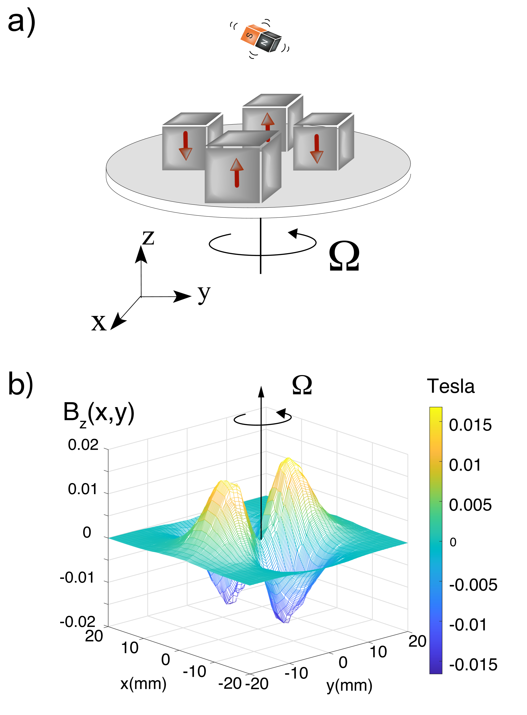
Figure 1-a) is a depiction of the platform that we employ. Opposite pairs of 5 mm square magnets are oriented so that their magnetic moments point to the same direction. The magnets are glued on the periphery of a copper baseplate. The distance between the center of the opposite magnet pairs is 20 mm. The assembly is attached to the spinning arm of the motor from a mechanical chopper. The motor can make this system rotate at a maximum frequency of 100 Hz, thus generating fast rotating magnetic fields along the directions. The direction can also be confined when the particle shape is taken into account, as will be explained later.
Consider a particle of mass which can move in a plane subjected to a saddle potential rotating at the frequency . We designate by the spatial coordinate of the particle in the laboratory-fixed frame and the coordinate in the rotating saddle frame. Adding an extra homogeneous magnetic field along fixes the particle angle along the direction. As shown in the Supplemental Material (SM), because of the typically large moment of inertia of the particles we trap, only a moderate homogeneous B field (in the mT range) is enough to ensure that the particle magnetic moment direction is not being defined by the B fields from the rotating magnets.
Figure 1-b) is the result of numerical simulations of the static magnetic field component along the direction as a function of and at a distance cm from the four-magnets trap. The magnetic field reaches about 0.1 T at maximum, and features a hyperbolic paraboloid shape close to . In the rotating frame, the magnetic field projection along around the saddle point reads :
| (1) |
where is the curvature of the magnetic field component along . In this frame, two forces must be added: the centrifugal force and the Coriolis force . The confinement along and comes from the competition between and . In the laboratory-fixed frame, the magnetic field is time-dependent and reads:
| (2) | ||||
The coupled set of equations of motions for the center of mass coordinates subjected to can be solved straightforwardly by averaging over one period of the trap oscillation (see SM, section 1). This procedure leads to ponderomotive confinements both in the and directions at trapping frequencies that are given by
| (3) |
Here, is the magnet density and T is the magnetization at saturation of the magnet. Using Hz, we obtain in the Hz range when the magnet lies a centimeter above the trap. Notably, in this geometry, the magnetic field is zero at the center at any position along . If the particle was a point-like magnet, there would be no confinement in the direction. A homogeneously magnetized particle whose form is invariant by rotations about an axis , will also not experience any force along if the symmetry axis coincides with . Indeed, the total force exerted by the four magnets on the whole body cancels out at any point in time. However, any deviation of the particle symmetry axis from the direction imposed by the external homogeneous magnetic field may give rise to a net force along onto the particle. When averaged over a cycle of the trap rotation, the particle would feel a ponderomotive force that pushes it away from the point. Another situation which could give rise to such a force along is when the particle is asymmetrical. Taking a parallelepiped with magnetic moment along , with a length along and a square cross-section with a side length , one finds (See SM section II) that the time-dependent potential along the direction reads :
| (4) |
where
| (5) |
Note that the radial potential is not impacted by this shape effect to first order. As expected the force is proportional to and the decrease of the magnetic curvature along gives rise to an outward force when averaged over one oscillation period. There will, in turn, be a local energy minimum thanks to gravity, thus confining the particle at a distance 1 cm from the trap (see SM section 1).
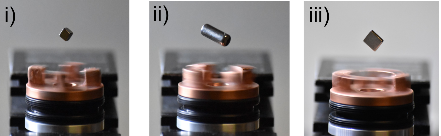
Experimentally, we find that at frequencies in the 50 to 100 Hz range, millimeter scale magnets can stably levitate for extended periods of time (more than hours) at a distance mm from the rotating baseplate where magnets are glued. Fig 2 i) to iii) show three photos of levitating magnets of different shapes and sizes. All three are neodymium iron boron magnets with a nickel coating. The three magnets are perfectly stable for all 6 degrees of freedom and over extended periods of time. A video of a levitating magnet can also be found in the supplemental materials. We found that placing magnets in a small water container above the trap and then removing the water using a syringe once they are stably trapped ensures efficient loading. The ease with which we can trap under water most likely stems from the increased capture volume as the damping is increased. After optimizing external homogeneous magnetic field directions and amplitudes using an extra permanent magnet, all of these magnets can be made stable angularly. The homogeneous magnetic field can indeed change the orientation of the magnet without perturbing the particle center of mass, as long as the magnetic field gradients at the particle location are negligible compared to the effective time-averaged magnetic field gradients from the saddle. We also found that the stator of the motor itself generates a strong enough static magnetic field that can also orient the magnet.
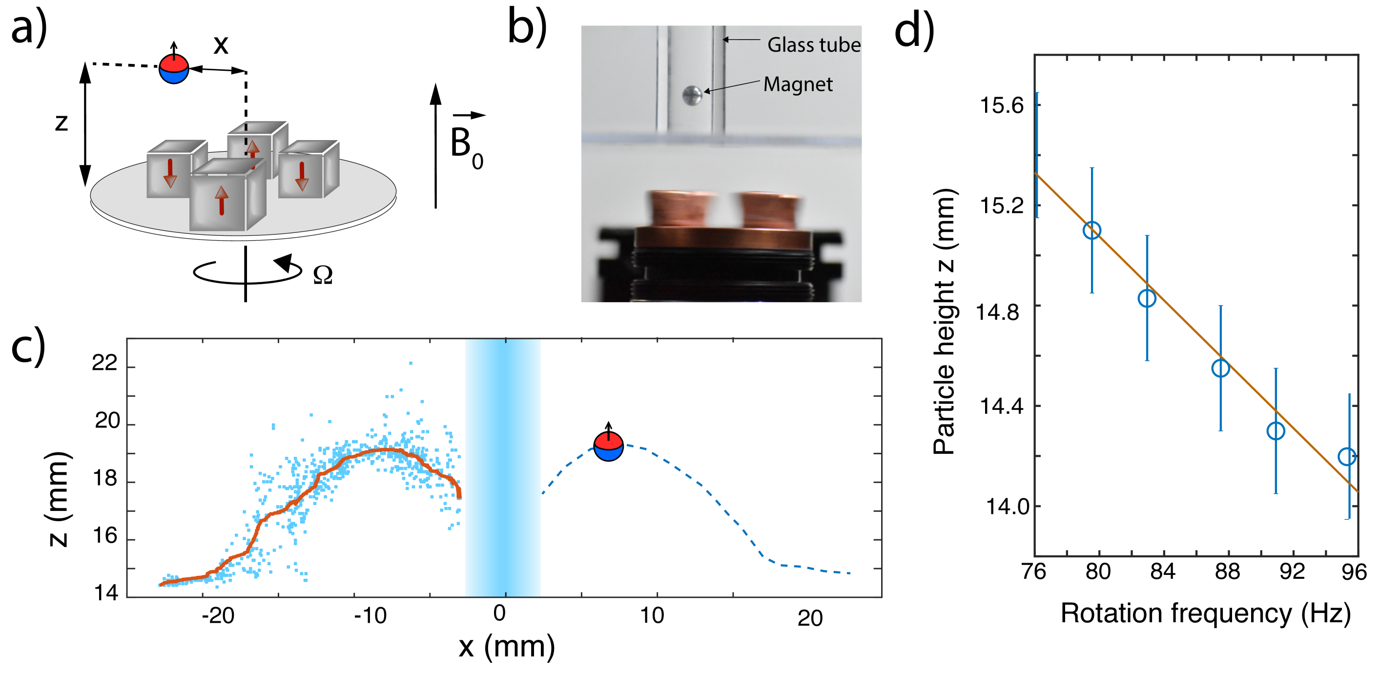
Numerical simulations (See SM, section 1-B) show good agreement with the experimental observations. In particular, the observed trapping height agrees with a model taking into account the particle shape. We also found further evidence that confinement along the direction arises because of the finite particle size by performing experiments with a millimeter-size spherical magnet. Confinement along was not observed for such particles, in agreement with Eq. 5, which predicts no confinement if in the trap center. Note that this is true only for small enough particles (See SM section I-B for a description of the limits of the model). In order to measure the dependent force when this particle is displaced from the trap center, we enclose the particle in a small glass tube and read-out its motion as the tube is displaced transversally. Fig. 3-b) shows a picture of the set-up and Fig. 3-a) is a schematic showing the employed parametrization. Fig. 3-c) are data where the center of mass position is monitored as a function of . The particle experiences no outward force when the tube is positioned such that mm and remains at the bottom of the tube. As the tube is displaced, the particle is lifted up, with a maximum height at mm, and then falls down again. This behavior is very well captured by numerical simulations where the outward force comes from the competition between ponderomotive force and gravity. Note also that, although extensive tests have been made, no trapping could be obtained after rotating the whole apparatus upside-down, which shows that the confinement is not solely due to the rotating magnetic field and that gravity plays a role. One last check is the dependency of the particle position with . Fig. 3-d) shows the height of a trapped 2.5 mm side cubic magnet (Fig. 2), as a function of . is seen to increase as the trap rotation frequency is increased, as expected from the ponderomotive nature of the outward force competing with gravity.
The off-centered position of the particle along is very convenient for the large optical access required for optical read-out of the motion. It will also facilitate the particle levitation in a vacuum chamber without having to integrate the rotating platform. Such planar traps are thus very attractive. As is the case with magnetic traps for neutral atoms or with ion traps, the most versatile way to trap particles while reaching high trapping frequencies together with open access is to employ chip-based designs consisting of current-carrying wires. Here, we propose the planar trap design depicted in Fig. 4-a) where an alternating current runs through a micro-wire in an externally applied homogeneous field . The total applied magnetic field on the ferromagnet at the center of this ring is the sum of a homogeneous field and an oscillating parabolic magnetic field which reads
| (6) | |||||
where is the laboratory-fixed axis, are spatial coordinates, is the curvature of and is the frequency of the magnetic field oscillation.
We consider a hard ferromagnetic neodymium microsphere with a radius . We use the convention for the three Euler angles (, , ) that parametrize the orientation of the magnet as well as the body-fixed magnetic moment orientation (see SM, section II). The norm of the magnetic moment is , where the volume of the ferromagnet and is the magnetization at saturation. In the basis, the magnetic moment is expressed as
| (7) | |||||
where and designate the cosine and sine function with arguments and is the shifted nutation angle defined as . By performing a second order Taylor expansion of the microsphere magnetic energy around the position , we obtain:
| (8) | |||||
Within the stability conditions (See SM, section 1-B), the alternating magnetic potential leads to a pseudo-harmonic confinement of the center of mass modes. After averaging the potential over one period of the magnetic field oscillation, we obtain the secular frequencies:
| (9) |
and
| (10) |
where Taking , where the secular harmonic approximation is valid and the following experimentally accessible values : , and , we obtain and . These trapping frequencies are on the order of the trapping frequencies that can be achieved using superconducting traps for micromagnets [12, 19], albeit here using a room temperature set-up.
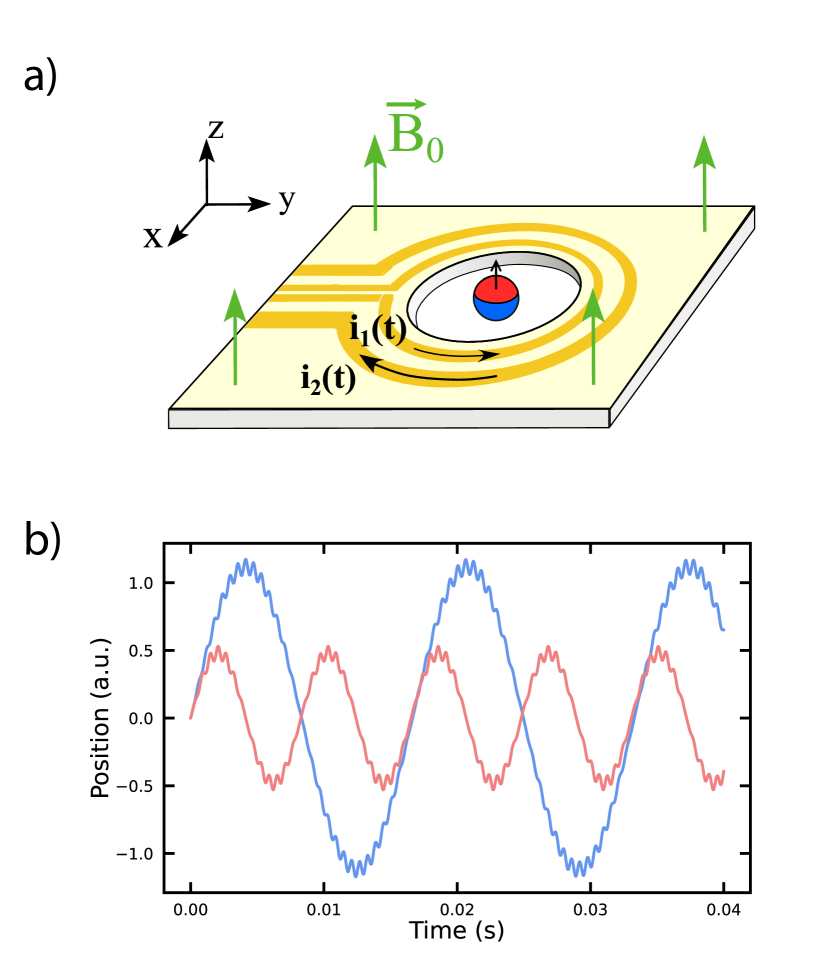
Fig. 4-b) shows the result of numerical simulations where the center of mass motion for the (blue curve) and (red curve) modes evolve as a function of time for a Paul trap frequency kHz. We see that as the magnet is displaced away from the position , a small high frequency oscillation appears after which the particle is brought back to . This observation is in accordance with the expected principle of the ponderomotive confinement and in good agreement with the above analytical calculations.
The shift of the center of mass position induced by gravity is . Such a shift will generate micromotion in the direction as well as a small coupling between the center of mass and the angular modes. We found that the gravity can however be compensated for by an external electric field if the particle is electrically charged or using a magnetic field gradient such that with . The coupling between the center of mass and the angular modes induced by this extra field can safely be neglected here (See SM, section 2).
While it is straightforward to experimentally generate the magnetic field , the generation of an oscillating magnetic field with a curvature requires a carefully engineered trap. We propose to employ a high-purity gold double-loop micro-trap with radii and made by lithography, on a silicon chip with alternating currents , with . The condition further suppresses the magnetic field at while keeping its harmonic dependency. The magnetic field curvature reads . This type of microchip can carry current of without experiencing too much heating [25, 26]. With a large and thin gold layer, the current equals A which leads to the desired value . The induced currents generated by one loop onto the other are found to be negligible (See SM, section 3). The Eddy currents created inside the levitating ferromagnet are also negligible compared to the gas dissipation process even under high vacuum (see SM, section 3). We thus expect no heating of the particle in this parameter regime.
The ability to control translational and rotational degrees of freedom of trapped particles with high precision has led to new opportunities for fundamental and applied research [6]. The high sensitivities of levitated objects to forces and torques in the motional ground state motivates research on tests of spin-mechanical coupling in the mesoscopic regime where gyromagnetic effects play a role. It is arguably beneficial to enrich the set of tools available to release some constraints that may be present in some trapping systems. As an example, optical levitation is typically prone to particle heating [27, 28, 29] and trapped charged particles to not lend themselves easily to approaching objects such as micro-fabricated optical components or other two-level systems [11] at distances below the micron. The presented magnetic Paul trap seems not to suffer from these problems and will thus enrich this already multidisciplinary research field.
Acknowledgements.
We would like to thank fruitful discussions with R. Folman, D. Budker, J. Wei, R. Blatt, O. Romero-Isart and P. Huillery. GH acknowledges funding from the Ile-de- France region in the framework of the DIM SIRTEQ. This project also received funding from the European Union’s Horizon 2020 Research and Innovation Programme under Grant Agreement no. 731473 and 101017733.References
- Paul [1990] W. Paul, Electromagnetic traps for charged and neutral particles, Rev. Mod. Phys. 62, 531 (1990).
- Welling et al. [1998] M. Welling, H. Schuessler, R. Thompson, and H. Walther, Ion/molecule reactions, mass spectrometry and optical spectroscopy in a linear ion trap, International Journal of Mass Spectrometry and Ion Processes 172, 95 (1998).
- Monroe et al. [1995] C. Monroe, D. M. Meekhof, B. E. King, S. R. Jefferts, W. M. Itano, D. J. Wineland, and P. Gould, Resolved-sideband raman cooling of a bound atom to the 3d zero-point energy, Phys. Rev. Lett. 75, 4011 (1995).
- Cirac and Zoller [1995] J. I. Cirac and P. Zoller, Quantum computations with cold trapped ions, Phys. Rev. Lett. 74, 4091 (1995).
- Perdriat et al. [2021] M. Perdriat, C. Pellet-Mary, P. Huillery, L. Rondin, and G. Hétet, Spin-mechanics with nitrogen-vacancy centers and trapped particles, Micromachines 12, 10.3390/mi12060651 (2021).
- Gonzalez-Ballestero et al. [2021] C. Gonzalez-Ballestero, M. Aspelmeyer, L. Novotny, R. Quidant, and O. Romero-Isart, Levitodynamics: Levitation and control of microscopic objects in vacuum, Science 374, eabg3027 (2021), https://www.science.org/doi/pdf/10.1126/science.abg3027 .
- Jackson Kimball et al. [2016] D. F. Jackson Kimball, A. O. Sushkov, and D. Budker, Precessing ferromagnetic needle magnetometer, Phys. Rev. Lett. 116, 190801 (2016).
- Rusconi et al. [2017] C. C. Rusconi, V. Pöchhacker, K. Kustura, J. I. Cirac, and O. Romero-Isart, Quantum spin stabilized magnetic levitation, Phys. Rev. Lett. 119, 167202 (2017).
- Kustura et al. [2022] K. Kustura, V. Wachter, A. E. Rubio López, and C. C. Rusconi, Stability of a magnetically levitated nanomagnet in vacuum: Effects of gas and magnetization damping, Phys. Rev. B 105, 174439 (2022).
- Vinante et al. [2021] A. Vinante, C. Timberlake, D. Budker, D. F. J. Kimball, A. O. Sushkov, and H. Ulbricht, Surpassing the energy resolution limit with ferromagnetic torque sensors, Phys. Rev. Lett. 127, 070801 (2021).
- Huillery et al. [2020] P. Huillery, T. Delord, L. Nicolas, M. Van Den Bossche, M. Perdriat, and G. Hétet, Spin mechanics with levitating ferromagnetic particles, Phys. Rev. B 101, 134415 (2020).
- Gieseler et al. [2020] J. Gieseler, A. Kabcenell, E. Rosenfeld, J. D. Schaefer, A. Safira, M. J. A. Schuetz, C. Gonzalez-Ballestero, C. C. Rusconi, O. Romero-Isart, and M. D. Lukin, Single-spin magnetomechanics with levitated micromagnets, Phys. Rev. Lett. 124, 163604 (2020).
- Timberlake et al. [2021] C. Timberlake, A. Vinante, F. Shankar, A. Lapi, and H. Ulbricht, Probing modified gravity with magnetically levitated resonators, Phys. Rev. D 104, L101101 (2021).
- Simon et al. [1997] M. D. Simon, L. O. Heflinger, and S. L. Ridgway, Spin stabilized magnetic levitation, American Journal of Physics 65, 286 (1997).
- Bachelet [1991] E. Bachelet, Levitating transmitting apparatus, US patent 1020943A, 6th of Dec. (1991).
- Druge et al. [2014] J. Druge, C. Jean, O. Laurent, M.-A. Méasson, and I. Favero, Damping and non-linearity of a levitating magnet in rotation above a superconductor, New Journal of Physics 16, 075011 (2014).
- Nemoshkalenko et al. [1990] V. Nemoshkalenko, E. Brandt, A. Kordyuk, and B. Nikitin, Dynamics of a permanent magnet levitating above a high-tc superconductor, Physica C: Superconductivity 170, 481 (1990).
- Hull and Cansiz [1999] J. R. Hull and A. Cansiz, Vertical and lateral forces between a permanent magnet and a high-temperature superconductor, Journal of Applied Physics 86, 6396 (1999).
- Vinante et al. [2020] A. Vinante, P. Falferi, G. Gasbarri, A. Setter, C. Timberlake, and H. Ulbricht, Ultralow mechanical damping with meissner-levitated ferromagnetic microparticles, Phys. Rev. Applied 13, 064027 (2020).
- Sackett et al. [1993] C. Sackett, E. Cornell, C. Monroe, and C. Wieman, A magnetic suspension system for atoms and bar magnets, American Journal of Physics 61, 304 (1993).
- Cornell et al. [1991] E. A. Cornell, C. Monroe, and C. E. Wieman, Multiply loaded, ac magnetic trap for neutral atoms, Phys. Rev. Lett. 67, 2439 (1991).
- BASSANI [2005] R. BASSANI, Stability of permanent magnet bearings under parametric excitations, Tribology Transactions 48, 457 (2005).
- Bassani [2006] R. Bassani, A Stability Space of a Magnetomechanical Bearing, Journal of Dynamic Systems, Measurement, and Control 129, 178 (2006), https://asmedigitalcollection.asme.org/dynamicsystems/article-pdf/129/2/178/5526944/178_1.pdf .
- Bassani [2007] R. Bassani, Dynamic stability of passive magnetic bearings, Nonlinear Dynamics 50, 161 (2007).
- Folman et al. [2000] R. Folman, P. Krüger, D. Cassettari, B. Hessmo, T. Maier, and J. Schmiedmayer, Controlling cold atoms using nanofabricated surfaces: Atom chips, Phys. Rev. Lett. 84, 4749 (2000).
- Feenstra et al. [2004] L. Feenstra, L. M. Andersson, and J. Schmiedmayer, Microtraps and atom chips: Toolboxes for cold atom physics, General Relativity and Gravitation 36, 2317 (2004).
- Rahman et al. [2016] A. T. M. A. Rahman, A. C. Frangeskou, M. S. Kim, S. Bose, G. W. Morley, and P. F. Barker, Burning and graphitization of optically levitated nanodiamonds in vacuum, Scientific Reports 6, 21633 EP (2016).
- Neukirch et al. [2013] L. P. Neukirch, J. Gieseler, R. Quidant, L. Novotny, and A. Nick Vamivakas, Observation of nitrogen vacancy photoluminescence from an optically levitated nanodiamond, Optics Letters 38, 2976 (2013).
- Hoang et al. [2016] T. M. Hoang, J. Ahn, J. Bang, and T. Li, Electron spin control of optically levitated nanodiamonds in vacuum, Nature Communications 7, 12250 EP (2016).