Analysis of an Explicit, High-Order Semi-Lagrangian Nodal Method
Abstract
A discrete analysis of the phase and dissipation errors of an explicit, semi-Lagrangian spectral element method is performed. The semi-Lagrangian method advects the Lagrange interpolant according the Lagrangian form of the transport equations and uses a least-square fit to correct the update for interface constraints of neighbouring elements. By assuming a monomial representation instead of the Lagrange form, a discrete version of the algorithm on a single element is derived. The resulting algebraic system lends itself to both a Modified Equation analysis and an eigenvalue analysis. The Modified Equation analysis, which Taylor expands the stencil at a single space location and time instance, shows that the semi-Lagrangian method is consistent with the PDE form of the transport equation in the limit that the element size goes to zero. The leading order truncation term of the Modified Equation is of the order of the degree of the interpolant which is consistent with numerical tests reported in the literature. The dispersion relations show that the method is negligibly dispersive, as is common for semi-Lagrangian methods. An eigenvalue analysis shows that the semi-Lagrangian method with a nodal Chebyshev interpolant is stable for a Courant-Friedrichs-Lewy condition based on the minimum collocation node spacing within an element that is greater than unity.
1 Introduction
In semi-Lagrangian (SL) methods, linear and non-linear transport equations of the form
| (1) |
where the flux is and is the advection velocity, are solved using the Lagrangian form of the equivalent system of characteristic ordinary differential equations,
| (2) | |||||
| (3) |
which traces the solution along characteristics with a wave speed, , which is divergence free, i.e., in one space dimension. The discrete location at which solutions are approximated are traced according to (3) over a single time step. This is followed by an interpolation of the advected solution back to its original location. This tracing and mapping can be applied in a number of ways, using combinations of approximations of (1), ((2) and (3) and interpolation and numerical integration methods [1, 2, 3, 4, 5].
In [8], we developed an explicit, high-order, semi-Lagrangian method that is consistent with a discontinuous spectral element method (DSEM) discretization of a complementary Eulerian model that supplies the advection velocity . The semi-Lagrangian method approximates the solution on nodes supporting a degree of polynomial per element. The location and solution on each node is updated according to (3) using the Eulerian solver’s . Combined with interface constraints that are found by connecting the solution on the interfaces of neighbouring elements, a least-square fit projects the solution back onto the original grid, where it can be coupled back if desired to the Eulerian field solver.
This semi-Lagrangian method ensures a boundary-fitted, higher-order accuracy approximation without the complications of Lagrangian-Eulerian, particle-mesh method interpolations [6, 7]. For further details on the method and its benefits, we refer the interested reader to [8]. The algorithm is even more effective in the Monte-Carlo solution of Fokker-Planck type equations using its equivalent of the Lagrangian-Langevin form [8]. A Lagrangian, Monte-Carlo update bypasses the curse-of-dimensionality of the Fokker-Planck solution and the associated computational expense.
To connect the elemental solutions thus far, we have used an upwinding approach and interface constraints combined with the least-squares fit [8, 9]. In many DSEM solvers [10, 11] a Lax-Friedrichs (LF) method or other approximate Riemann solver is used to find the interface flux as a function of two neighbouring elemental solutions. To be consistent with such upwinding, the LF coupling is thus desirable for the semi-Lagrangian update, too. An additional advantage of the LF solver as compared to the upwind solver is that it is slightly easier to generalize for non-linear problems.
The impact of the interface flux specification on the numerical properties of the explicit, semi-Lagrangian method is not trivial. Semi-Lagrangian methods are known for their complete absence of dispersion as waves are traced exactly. Moreover, the method is stable for high Courant-Friedrichs-Lewy () numbers. This comes at a cost of considerable complexity of the traced basis and its mapping to the original basis. In the explicit semi-Lagrangian method that we proposed in [8], the characteristic information is only approximately enforced. As compared to most semi-Lagrangian methods, this reduces the stable and may affect the diffusion and dispersion characteristics.
In addition to the basic properties of a numerical method, including accuracy, convergence, and stability, the properties of advection problem approximations are often also characterized through the diffusion and dispersion relations that follow from an eigenvalue analysis of spatial flux derivative. An eigenvalue analysis provides a spectrum of the equivalent numerical wave frequencies as compared to the exact frequency, and shows to what extent waves at each frequency are accurately represented [12].
Alternatively, for finite difference methods at least, a Modified Equation Analysis (MEA) proves useful. In MEA, the dependencies of the solution on multiple grid points within an approximation stencil are reduced to a single nodal point using Taylor series, with the objective being to find an equivalent transport PDE with a modified right hand side that summarizes the effect of truncation terms of the Taylor series. For higher-order methods, this analysis is not common. Only Costa et al. [13] report on MEA for modal discontinuous Galerkin methods. They present examples that provide evidence of the validity of a MEA analysis and its good comparison, albeit for lower wavenumbers, with an eigenvalue analysis [12].
Here, we revisit the semi-Lagrangian method of [8] and present a discrete analysis, including MEA and an eigenvalue analysis of the recursive discrete system. By assuming a monomial approximation in each element, we derive the discrete version of the algorithm on a single element with upwinding and Lax-Friedrichs interface patching. The resulting algebraic systems lend themselves to both the Modified Equation Analysis (MEA) and an eigenvalue analyses.
The approach we follow here is distinctly different from [13] for a number of reasons: firstly, we are concerned with a semi-Lagrangian method that does not require differentiation; secondly, we consider a collocation, strong form spectral method and thirdly, we use a monomial polynomial form for analysis. To the best of our knowledge, no such analysis has been attempted for high-order semi-Lagrangian methods. The analysis sheds light on the influence of polynomial order, time stepping, grid spacing, interface patching on dispersion, diffusion and stability of the method.
To introduce notation and for reference, we will first briefly review the explicit semi-Lagrangian method. Then we start with the derivation of the discrete zeroth order semi-Lagrangian method using the monomial form and analysis thereof. This sets stage for an extension to a first-order derivation and analysis followed by a presentation for a general order .
2 Semi-Lagrangian method
The explicit, high-order semi-Lagrangian method [8] solves the hyperbolic conservation laws in (1) on the domain . (See a schematic in Fig. 1.) The method subdivides into non-overlapping elements so that . Each element is mapped onto a local coordinate . The element’s solution at a given time is approximated with a Lagrange interpolant of degree as follows
| (4) |
where are the solution values at nodal points with superscript identifying the time instance. The basis function, , is the Lagrangian interpolating polynomial defined at the Chebyshev Gauss quadrature nodes ,
| (5) |
mapped onto .

The nodal coordinates and solution values, i.e., the interpolant, are advected in time according to (2) and (3)
| (6) |
with an explicit time integrator (Euler for the sake of simplicity of notation here). The advected interpolant is then projected back to the quadrature nodes so that
| (7) |
with the Lagrange polynomial defined on .
It remains to correct the solution for neighbouring elements and boundary conditions. To identify boundary locations, we introduce a global counter, , whose coordinate, , coincides with the center coordinate of element , i.e., . Variables with fractional subscript counters identify inter-element face locations so that . For the MEA below, this notation is particularly helpful, as we will find a Modified Equation at the global coordinate using Taylor expansions. The boundary value at the interface between element and is denoted as , see Fig. 1, which is determined from the face values of neighbouring elements, which we denote as (to the left of the interface) and (to the right of the interface). We therefore write
| (8) |
where the superscript identifies the inter-element values that results from the solution of a Riemann problem according to some function from the two face values. and are interpolated to the edge locations using (7).
In our previous work [8] we took to be the upwind solution. Alternatively, here we will consider a more general Lax-Friedrichs weighting of the solutions from either side [14]
| (9) |
where
| (10) |
and is the maximum wave speed in and the minimum spacing between the nodal points in the global coordinate . The Courant-Lewy-Friedrichs number is denoted by .
With the two additional constrains on each face of the element, a least-squares minimization is used to update the solution to time level as
| (11) |
where is the vector that contains the nodal solution values and the boundary constraints,
| (12) |
3 Analysis of the Semi-Lagrangian Approximation
In this section, we derive the modified equation associated with the semi-Lagrangian approximations. We start with the lowest order, , for its simplicity, and then increase the complexity by analysing before moving to the general case. The results for the low order schemes give insight into the more general results, and the derivations are easier to follow.
3.1 Zeroth order, =0
First, we analyze the discrete semi-Lagrangian method for a zeroth order () approximation of the solution within the element at its center nodal point, ,
| (13) |
The nodal coordinate, , and solution are first updated according to (2) and (3),
| (14) | |||||
| (15) |
where the time step is chosen so that the nodal point remains within the element’s bounds ,
| (16) |
with and .
The solution is then interpolated back to the nodal point . Because the approximation is zeroth order and because the solution remains within the bounds of the element, the updated, interpolated, solution at the nodal point is the same as the solution at ,
| (17) |
The interpolant is corrected for boundary constraints, and at both edges of the element using a least square approach, so that the error
| (18) |
is minimized. Setting the derivative , it follows that
| (19) |
It remains to determine the boundary constraints. To connect neighbouring volumes, the Riemann problem
| (20) |
must be solved or approximated. We propose to use a Lax-Friedrichs upwinding as
| (21) |
where, comparing to (9), we have multiplied the flux term with a factor three so that it cancels out against the denominator in (19). Substituting (21) and (17) into (19) yields
Simplifying leads to
| (23) |
Remarks:
When ,
-
The stencil in (23) is similar to the Lax-Friedrichs (LF) method in (9), but the average term on the right-hand side is distinctly different. Like LF, the method is diffusive, which can be understood if is subtracted from both sides of (23). Then a second order central difference approximation to a diffusive term emerges with a diffusion coefficient of . For LF, a similar term can be shown to appear, but with a diffusion coefficient of , making LF more diffusive.
-
The factor three in (21) is required to obtain the second term on the right hand-side in (23), which correctly represents the approximation to the flux derivative in the Eulerian form and thus, in light of the previous remark, ensures conservation and a correct wave speed of the approximate solution. As opposed to Eulerian DSEM methods, the semi-Lagrangian method is not flux based and thus is not trivially conservative. Because of the flux correction inherent to the Lax-Friedrichs method, the flux difference in (23) recovers the conservation property. We will explore this flux correction for general high-order semi-Lagrangian schemes in the sections below.
-
If a simple upwind method where used in (20) instead of LF, then that would eliminate the flux term and wave speed from the approximation and thus result in a meaningless scheme.
-
Because the solution in (17) does not change at the nodal location for the zeroth order advection and projection, this step can be considered Eulerian in some sense.
-
A least-squares method belongs to a general class of minimization methods that are commonly used to approximate Eulerian forms of the equation using Galerkin methods.
3.1.1 The Modified Equation
Assuming linear advection with constant , and Taylor expanding all terms in (23) around and , we find the ME
| (24) |
Here, we have used (1) to relate temporal derivatives to spatial derivatives. The ME shows that the leading order term is and implies that the =0 semi-Lagrangian method is first order accurate.
The ME confirms that the approximation is diffusive and dispersive. For stability of the scheme, it is required that the diffusion coefficient be positive, which can be ensured by a time step restriction
| (25) |
Computational tests (not presented here) of a linear advection of sine wave show that this stability criterion is not sufficient. For 0.6, numerical solutions are unstable. A Von Neumann analysis on the discrete stencil (23) confirms this more precisely, and that the stable . Note, that the time step should obey (10) with because the should not be advected beyond the right edge of an element.
Rewriting (24) in terms of using (10) leads to
| (26) |
which shows that both the dissipation and dispersion error will reduce with grid spacing. The in the denominator of the first term on the right hand side means that the numerical diffusion will go to infinity in the limit of a zero time step, while maintaining a constant grid spacing. To mitigate this, the time and grid spacing must be reduced simultaneously. It is likely that this is a property is inherent to the Eulerian-Lagrangian duality of a semi-Lagrangian method.
3.2 First-Order, =1, Semi-Lagrangian Method
To derive the discrete form of the semi- Lagrangian method for , we find that a monomial representation of the basis enables analysis that the Lagrangian interpolant in (4) does not. To derive the discrete stencil, we therefore start from a first-order monomial defined on two nodal points, and within the element as
| (27) |
where is the polynomial of degree one at . The coefficient is the slope of the line and is determined as
| (28) |
It then follows that is
| (29) |
Once again, in the first step of the semi-Lagrangian method, the polynomial is advected according to its advection velocity. For simplicity we take a constant , so that
| (30) | |||||
| (31) |
which translates the straight line in the positive -direction. A linear interpolation projects this line back onto the original grid as
| (32) |
We can rewrite (32) using (28) as
| (33) |
Note that the second term on the right hand side of (33) represents the solution shift of the linear approximation with an element from to and is thus per the Eulerian conservation law indicative of the mass flux through the element interface over the time step . In fact, we can use the definition of the flux to rewrite the equation in terms of the flux difference as
| (34) |
This , together with boundary constraints and , determines using a least-square fit. For this fit we define the error as:
Minimization with respect to and leads to
| (36) |
where
| (37) |
Solving for and yields
| (38) | |||||
| (39) |
Note that and are predetermined and depend only on the coordinates. Only and depend on the solution. and have a flux update according to (32).
To understand the impact of the distribution of the nodal points within an element, we will consider a variable, symmetric nodal point distribution per element per the schematic shown in Fig. 2. We will assume the spacing between and to be so that and . Then we can write out and and simplify using (32) to get the interior point values
| (40) | |||||
For the symmetric node distribution, =0 and , so (39) can be further simplified to
| (41) | |||||
| (42) |
With these coefficients the updated monomial at is determined. What remains are the boundary constraints in and . We will discuss using an upwind scheme and a LF scheme for the boundary constraints in the next two subsections.
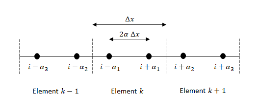
3.2.1 The Modified Equation
In this section we consider two interface conditions, one with pure upwinding, and the other with the LF coupling.
Upwinding. Assuming a positive constant advection velocity, , the upwind scheme generates the interface constraints, , as
| (43) |
where the subscript identifies the element number. Then using (39) , the updated solution at the global grid coordinate, , is given by
| (44) | |||||
Substituting (40) and (43) into (44) leads to the discrete stencil
| (45) | |||||
To find the Modified Equation, each term is Taylor expanded around and ,
| (46) |
From the PDF from of the advection equations (1), it follows that and . Using these substitutions and substituting the Taylor expansions (46) into (45) yields the ME,
| (47) | |||||
Replacing according to (10) with , we can rewrite the modified equation as
| (48) | |||||
The leading order term is of , i.e., the method is also first order accurate. The diffusion and dispersion coefficients both depend on the and the grid point distribution, .
Lax-Friedrichs. The Lax-Friedrichs scheme determines the interface constraint according to (9), as
| (49) |
where we have introduced a factor to adjust the weight of the flux correction, similar to the factor of three that was used in the zeroth order method above. Note that for a constant advection velocity and with , the upwind method in (43) is recovered if , and thus the ME should be the same for LF as compared to upwind for this .
Assuming a positive constant advection velocity, , the LF scheme according to (49) determines the interface constraints, , as
| (50) | |||||
Substituting (40) and (50) into (44) leads to the discrete stencil
| (51) | |||||
Note that if we substitute , the upwind stencil in (47) is consistently recovered.
Using the Taylor’s series expansion and the relations between space and time derivatives from the PDE, we arrive at the ME for the semi-Lagrangian scheme with the Lax-Friedrichs interface constraint,
| (52) | |||||
This scheme, like the scheme with the upwind constraint per (47), is therefore first order accurate according to the leading order term on the right-hand side. Consistently, if we compare the two MEs for the upwind and LF constraint, i.e., (47) and (52), then it is clear that once again with the MEs are the same. Replacing according to (10) with , we can rewrite (52) as
| (53) | |||||
We explore the stability and accuracy characteristics of (53) by setting the diffusion coefficient to zero, which requires that
| (54) |
If the diffusion coefficient is greater than zero the method is diffusive in the second order term. For a zero diffusion coefficient, the method increases in accuracy by one order and the diffusion is in the fourth order derivative term with respect to . Just like for the zeroth order method discussed in the previous section, it is possible to set so that the accuracy increases, but for this depends on , i.e., the distribution of the nodal locations, as well. Thus, for any given and , there is a corresponding that sets the diffusion coefficient to zero.
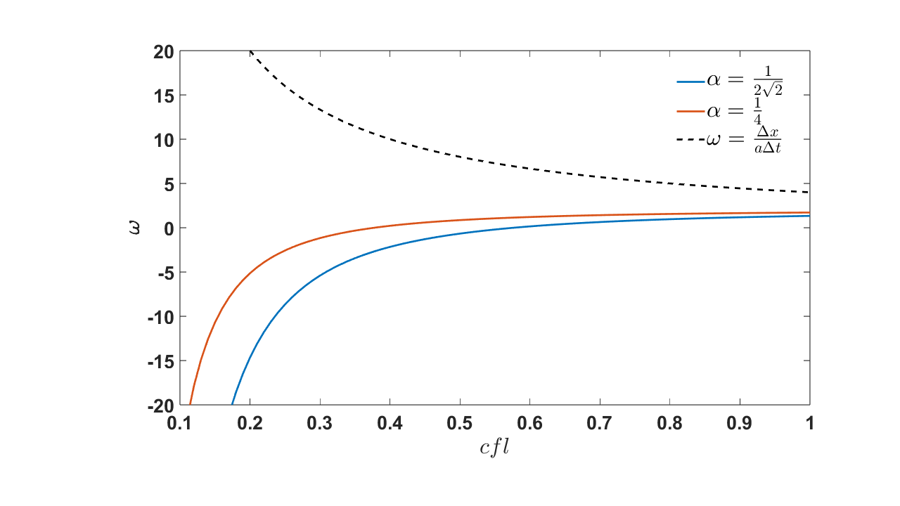
The dependencies of the zero diffusion coefficient on , , and are summarized in Figures (3a) and b), respectively. While we plot on the vertical axis for convenience, it should not be interpreted as a variable that is dependent on and . Rather, all three variables are the independent variables used to zero the diffusion coefficient and thus can be varied independently to enforce that property. For reference, the trend for the upwind scheme, for which the diffusion coefficient is positive, is also plotted using the relation . With a decreasing value of , the graphs show that also decreases and can become negative in order to produce a zero coefficient on the first order diffusive term. This trend can be understood by inspecting (54); the first term is positive and increases with decreasing , and thus the third term, , must decrease accordingly to satisfy the equality. The difference in the positive value of for the positive diffusion coefficient of the upwind scheme and the negative for the zero diffusion coefficient goes to infinity if the nodal distribution clusters around the center point when tends to . In general, has to be larger for the Chebyshev distribution for the same to obtain zero diffusion.
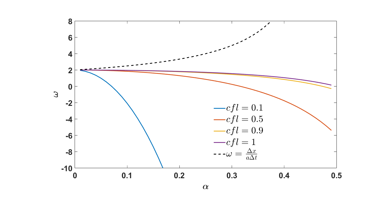
(a)
(b)
3.3 Generalized analysis for
To generalize the analysis for , we start with the monomial of degree at in the element as
| (55) |
The coefficients can be obtained by solving the system
| (56) |
where the matrix on the right-hand side is the inverse of the Vandermonde matrix, . We will use the definition of the vector of basis functions,
| (57) |
to alternatively denote the Vandermonde matrix as
| (58) |
with . In matrix-vector notation, we write (56) as
| (59) |
where the second superscript identifies the element number.
In the next step of the semi-Lagrangian process, the polynomial is advected according to the advection velocity ,
| (60) |
Then we project the advected solution back to the original basis. First, we find the updated coefficients as
| (61) |
where the modified Vandermonde matrix, , is determined using the advected coordinates with
| (62) |
where . Then the updated solution is
| (63) |
For the “least-squares fit” stage of the algorithm that corrects for boundary/interface solutions, we first define the error as
| (64) | |||||
Setting the derivative of the error with respect to the coefficients =0
| (66) |
leads to a system of equations that can be solved for
| (67) | |||||
Rewritten in matrix-vector notation this leads to
| (68) |
We shall denote this short-hand in matrix-vector form as
| (69) |
We next need to express the interface/boundary solutions in terms of the interpolant in the neighbouring elements. We start by determining the coefficients in the neighbouring elements according to (61), then use those coefficients to evaluate the solutions at the interface and apply the Lax-Friedrichs Flux, which leads to
| (70) |
This completes the algorithm. We can write the interface values in vector notation also as
| (71) | |||||
| (72) | |||||
| (73) |
where denotes an inner product of two vectors. Now using the definition of the vector that includes the boundary corrections according to (12) as
| (75) |
with , where the superscript identifies a transpose, we can express as
| (76) |
where we have used the notation to identify a vector whose elements are taken to the power as
| (77) |
Using this same notation, we can write the matrix as
| (78) |
Now we can express in terms of as
| (80) | |||||
This can be written in shortened notation as
| (81) |
with the size of all matrices being as
| (82) |
The updated solution in (81) through a recursive relation and a single, recursive matrix-vector operation which lends itself to further analysis.
For the sake of a simplified analysis, it is common to take periodic boundary conditions [12]. If we assume periodic boundary conditions then and . In that case and are
| (83) |
which can be combined with so that
| (84) | |||||
Then (81) simplifies to
| (85) |
To obtain periodicity we could also just set and in (81).
3.3.1 The Modified Equation and Convergence Rates
To derive the Modified Equation, we must decide on the nodal point distribution. For simplicity, we will consider equidistant local node coordinates
| (86) |
These local coordinates coincide with the global coordinates of the element as
| (87) |
for an even if the center nodal point is chosen at . For the sake of this analysis we determine the coefficients , and using the global coordinates
| (88) | |||||
| (89) | |||||
| (90) |
Then we use the coefficients in (68) to determine the solution at as
| (91) |
Then a Taylor series analysis can be performed at this center location to obtain the modified equation. We have verified that the procedure just outlined leads to the MEs equations derived for and in the previous sections.
For we find that the ME is
| (92) |
The leading order term is second-order, i.e. the convergence rate is the same as . We find the same order of accuracy for other nodal distributions, including the Chebyshev Gauss quadrature nodes, but the coefficients on the truncation terms are dependent on the nodal point distribution consistent with the discussion for the method above. It turns out that in the derivation of MEs for other , the semi-Lagrangian method is order accurate, i.e., the leading order truncation term is of order . To underscore, we give the leading order term in the ME for
| (93) |
which is fourth order. Note that the leading order coefficient is once again dependent on , and and that is possible to remove one of the leading terms by balancing these values so that the coefficient is zero.
While the ME provides insight into the leading order behavior of convergence, diffusion and dispersion, it was already shown to be insufficient to understand stability, diffusion and dispersion comprehensively in the case. To this end, we need to understand the dispersion and diffusion for all wave content.
3.3.2 The Diffusion and Dispersion Relations
Following [13] we use the Modified Equation to find the approximate dispersion and diffusion relations by considering a solution of the form
| (94) |
with . Substituting the solution ansatz into the governing advection equation (1) leads to
| (95) |
When (94) is substituted into the Modified Equation, then the high order spatial derivatives of the truncated terms change the expression to
| (96) |
where is the effective wave number that can be directly compared to of the original advection equation. Costa et al. [13] report that the more expansion terms are accounted for in the Modified Equation and , the more accurate the dispersion relation is in approximating a formal eigenvalue analysis for the entire wave number spectrum of an Eulerian grid based discontinuous Galerkin method.
Fig. 4 plots the real and imaginary part of found using thirteen Taylor series expansion terms for , and with an equidistant nodal distribution. Recognizing that and ), these plots can be interpreted to understand the diffusive and dispersive nature of the semi-Lagrangian method.
With increasing the method remains diffusive for all , but less so since the drop-off in the diffusion occurs at higher . The dispersion relation for shows a known trend: For higher , the semi-Lagrangian has a near zero dispersion as can be expected for a method that essentially traces the characteristics. For and the effective wave number is slightly higher than the exact wave number. At higher wave numbers the number of truncation terms significantly affects the accuracy of the effective dispersion relation.
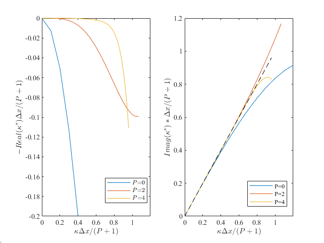
(a) (b)
3.3.3 Stability
The updated solution in (85) is recurrent and the matrix is the amplification matrix that can be analyzed by determining its eigenvalues of
| (97) |
The largest eigenvalue of represents the spectral radius and its absolute value , should be less than unity to ensure stability.
The conditioning of the matrices and contribute to the magnitude of the spectral radius. Upon inspection, appears to be diagonally dominant. But because most terms on the diagonal have terms of to some power in the denominator and because the first entry of the matrix is a constant, it follows that for small , may not be positive definite. is a sparse matrix because of symmetry of the collocation points. The conditioning of the modified Vandermonde matrix, , depends on the distance that semi-Lagrangian particles travel away from their original seeding at the collocation nodes. The deviation from the seeded quadrature points determines the amount of extrapolation as shown (1) and the related condition number of the interpolant and inverse of Vandermonde matrix. The condition number grows with the advected distance of the collocation nodes.
Example for P=2
With and periodic conditions according to (85) the eigenvalues are
| (98) |
showing a double eigenvalue with a negative unity magnitude . It turns out that for a single periodic element these eigenvalues are complex conjugates and hence the solution to this problem is unstable.
If instead of the periodic system, we impose boundary conditions by setting and in (81), then we find the eigenvalues are real and unique and depend on and as plotted in Fig. 5 for a fixed value of . Particularly, if the trends show three separate branches, then all the eigenvalues are real and their absolute value is smaller then unity, i.e., the recursive relation and thus the semi-Lagrangian method is stable. When branches merge, the eigenvalues are complex conjugates like for the periodic system, and the solution is no longer stable. This merging of branches occurs at different limits for different nodal point distributions. Chebyshev nodal distribution approximations are well-posed for . The limit for uniform nodal increases slightly with an increased , but is much less (smaller than unit) as compared to the limit for the Chebyshev nodal distribution. The eigenvalues of the lower branch tend to -1 in the limit that goes to zero, suggesting a marginally stable scheme for very small . This is consistent with the observation made for =0 above that shows that and should not be independently changed.
A von Neumann (VN) analysis can be performed using the recurrent discrete stencil (91) at the center node. This stencil was also used to derive the Modified Equation for an equidistant collocation node spacing. A more precise, stable criterion follows from VN analysis as it does not require the single element periodicity assumptions that were used to find the spectral radius. The stable for with according to VN is and for schemes with (upwind scheme) and (standard Lax-Friedrichs) respectively, confirming the explicit stability of the semi-Lagrangian method for greater than unity.


4 Numerical Tests
Numerical tests are conducted to verify the analysis of the semi-Lagrangian method with a Lax-Friedrichs flux correction. To do so, the linear advection equation (1) is solved with =constant=1 with an initial sine wave condition
| (99) |
in the domain .
4.1 Marginally resolved
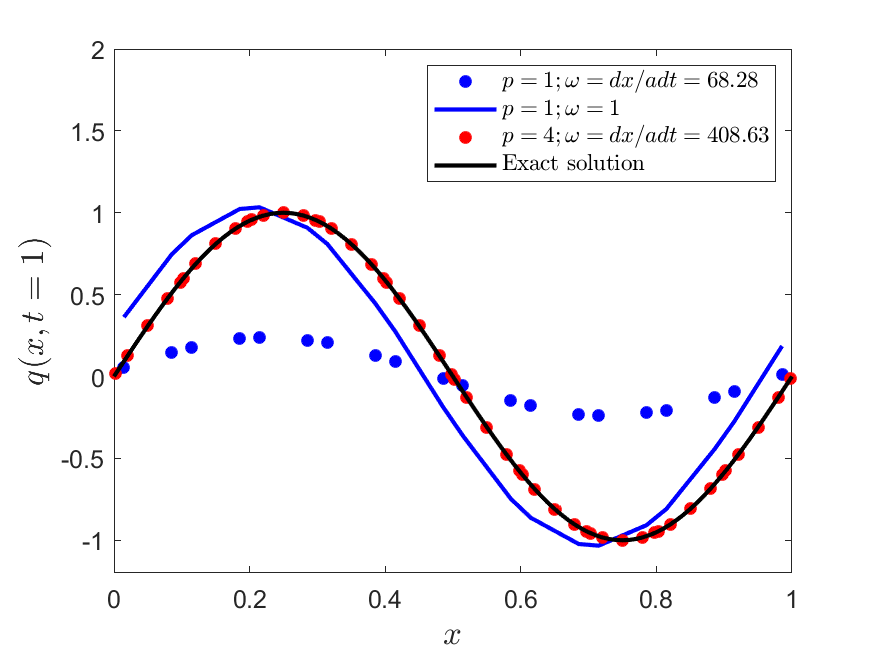
We start by performing marginally resolved simulations to illustrate the diffusive and dispersive behavior of the first-order () semi-Lagrangian scheme with a Chebyshev spacing of the collocation nodes. To this end, we set and the number of elements, . We consider two cases; one for which, according to an upwind flux and for another we take according to a standard Lax-Friedrichs method. Figure 6 compares the analytical and numerical solution so determined after one time period. Whereas the results show that the upwind scheme is dissipative (reduced amplitude), the standard LF scheme is mostly dispersive (phase shift of the wave). This is consistent with the Modified Equation analysis, which concluded that the leading order disspative term reduces in magnitude with reduced . Then naturally, with a reduced diffusion, the next order dispersive terms takes over. Also plotted in Figure 6 is an upwind SL solution with , which shows that the higher order scheme is noticeably more accurate and less dissipative.
4.2 Convergence
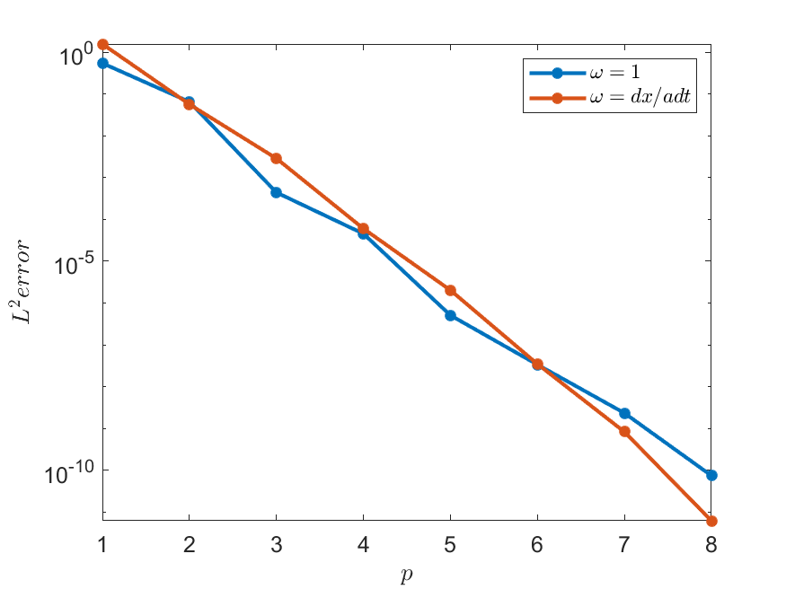
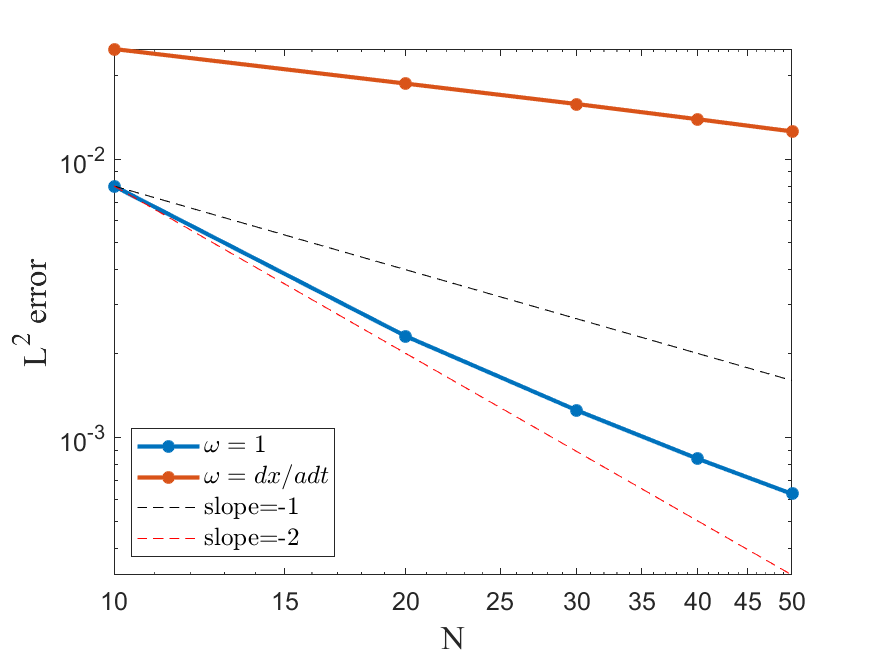
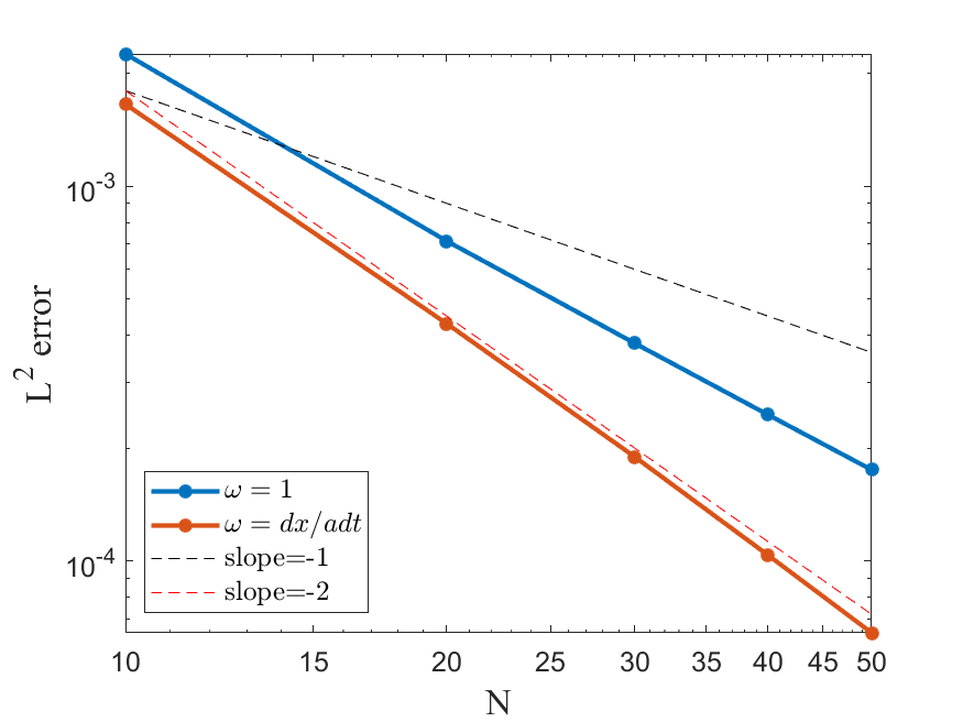
To underscore and quantify this accuracy improvement and to validate the theoretical convergence order of as predicted by the ME analysis up to , the convergence of the error versus is plotted for the uwpind SL scheme in Figure 7 using and . The plot confirms the exponential convergence at a rate for both the upwind scheme and the scheme with . Algebraic convergence is further confirmed to be order for and in Figure (8). The upwind scheme exhibits a consistent convergence rate of for a number of elements ranging from to . These rates were also found for several benchmark problems in [8]. The standard LF flux correction with appears to converge at for , but the rate reduces to for a larger number of elements. Based on the ME analysis, this convergence rate reduction can be explained by comparing the magnitude of the leading order diffusive term to the next order dispersive term as follows: for a marginally resolved numerical solution, the leading order term in the ME is smaller for a reduced as compared to the upwind scheme. So, the dispersive term may even be larger than the diffusive term at . With an increased resolution the dispersive term asymptotically reduces faster to zero with reduced grid spacing as compared to the diffusive term because it is of a higher order.
(a) (b)
4.3 Stability
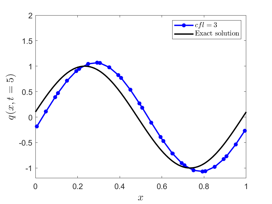
To verify the findings of the stability analysis, we simulate the sine wave with , and . The is increased until it is observed that the amplitude of the sine wave increases with time at which point the method is deemed unstable. Simulations are found to be unstable approximately for . Figure 9 illustrates this unstable increase of amplitude for a sine wave solution that is advected for five periods with a . The expected stability limit predicted by the spectral radius analysis for a one-domain periodic case is however . The difference between this theoretical and the numerically stable proofs that the one-domain spectral radius analysis is not sufficient to predict the exact stability limits. This observation is consistent with the conclusions made for and by comparing the results of a Von Neumann analysis for and with stability limits predicted by the ME equation analysis. Both in the ME analysis and the single domain spectral radius analysis, higher order modes or truncation terms are not accounted for that prevent the exact determination of the stable criterion.
4.4 Enhanced convergence
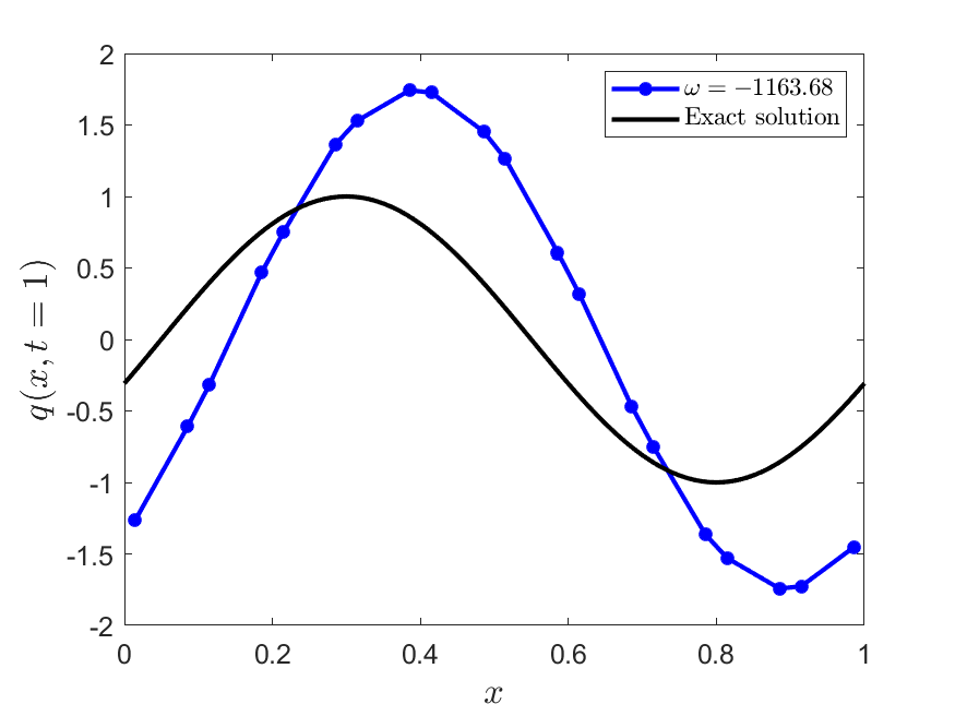
The ME equations analysis suggests that one could choose a flux correction, , and/or the collocation point distribution (e.g. according to for ) such that the leading order term is zero and the convergence rate increases by one order. To test this idea, we simulate the sine wave and set , the value at which the leading term in the truncation error becomes zero. For , the truncation is according to the right hand side of (53).
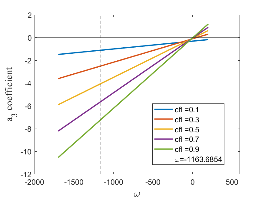
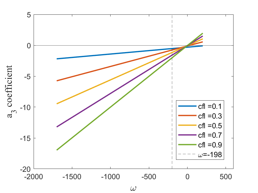
Unfortunately, simulations with and using Chebyshev points with the corresponding, are unstable as illustrated in Figure (10). To understand this behavior, we plot the coefficient of the third order truncation term in the ME versus in Figure (11). Note that this terms is next even order diffusion term after the leading first-order diffusion term. Clearly, the coefficient is negative if for a uniform and a Chebyshev nodal distribution, and tested values. Thus the solution is mildly anti-diffusive and hence becomes weakly unstable. We have confirmed with a Von Neumann analysis for an equidistant nodal spacing that signs in the Taylor series of the dissipation factor can alternate in the higher-order terms, and so choosing the parameters using only the leading order term need not lead to a stable scheme in the critical case.
(a) (b)
5 Conclusions
The discrete, spatio-temporal, recursive stencil is derived for a semi-Lagrangian spectral element method that updates a piecewise continuous interpolant according to the Lagrangian (characteristic form) of the transport equations. The derivation hinges on the use of the monomial form of the interpolant and the corresponding, invertible Vandermonde matrix of the resulting interpolant.
A Modified Equation (ME) analysis, which Taylor expands the stencil in space and time to a single space and time location, shows that the semi-Lagrangian method is consistent with the PDE form of the transport equation in the limit that the grid spacing goes to zero for smooth solutions. The leading order truncation term of the ME is order, which is consistent with the numerical tests presented in previous work [8].
The nodal point distribution affects the coefficient of the truncation terms. It is in general possible to increase the order of the method by one order for a linear, one-dimensional form of the equations. It remains to be seen if this can be generalized to general element in multi dimensions.
The approximate diffusion and diffusion relations derived by comparing the wave content of multiple truncation terms of the ME show that the higher order semi-Lagrangian method has very little dispersion at low wavenumbers, as one might expect from a semi-Lagrangian method.
An eigenvalue analysis of the recursive, algebraic form of the semi-Lagrangian method shows that the is limited by numerical stability. The limit depends on the nodal point distributions with an element. For a Chebyshev point distribution, the semi-Lagrangian method is stable for values of significantly greater than unity.
References
- [1] A. Staniforth and J. Cote. Semi-Lagrangian integration schemes for atmospheric models- a review. Monthly weather review, 119:2206, September 1991.
- [2] L. M. Leslie and R. J. Purser. Three-dimensional mass conserving semi-Lagrangian scheme employing forward trajectories. Monthly weather review, 123:2551, 1995.
- [3] R. Miodrag. Semi-Lagrangian piecewise biparabolic scheme for two-dimensional horizontal advection of a passive scalar. Monthly Weather Review, 120(7):1394–1406, 1992.
- [4] J.-M. Qiu and C.-W. Shu. Positivity preserving semi-Lagrangian discontinuous Galerkin formulation: Theoretical analysis and application to the vlasov-poisson system. Journal of Computational Physics, 230(23):8386–8409, September 2011.
- [5] F.X. Giraldo. The Lagrange–Galerkin spectral element method on unstructured quadrilateral grids. Journal of Computational Physics, 147:114–146, 1998.
- [6] G.B. Jacobs and J.S. Hesthaven. High-order nodal discontinuous Galerkin particle-in-cell method on unstructured grids. Journal of Computational Physics, 214:96–121, 2006.
- [7] J.P. Suarez, G.B. Jacobs, and W.S. Don. A higher-order Dirac-delta regularization with optimal scaling in the spectral solution of one-dimensional singular hyperbolic conservation laws. SIAM Journal of Scientific Computing, 36(4), 2014.
- [8] H. Natarajan and G.B. Jacobs. An explicit semi-Lagrangian, spectral method for solution of lagrangian transport equations in Eulerian-Lagrangian formulations. Computers and Fluids, 207, 2020.
- [9] H Natarajan, PP Popov, and GB Jacobs. A high-order semi-Lagrangian method for the consistent Monte-Carlo solution of stochastic Lagrangian drift–diffusion models coupled with Eulerian discontinuous spectral element method. Computer Methods in Applied Mechanics and Engineering, 384:114001, 2021.
- [10] D.A. Kopriva. Implementing Spectral Methods for Partial Differential Equations: Algorithms for Scientists and Engineers. Springer Netherlands, 2009.
- [11] J.S. Hesthaven and T. Warburton. Nodal discontinuous Galerkin methods: algorithms, analysis, and applications. Springer-Verlag, Berlin, 2008.
- [12] Gregor Gassner and David A. Kopriva. A comparison of the dispersion and dissipation errors of Gauss and Gauss-Lobatto discontinuous Galerkin spectral element methods. SIAM Journal on Scientific Computing, 33(5):2560–2579, 2011.
- [13] R. Costa Moura, S. Sherwin, and J. Peiró. Modified equation analysis for the discontinuous Galerkin formulation. volume 106, pages 375–383. Springer, 2015.
- [14] R. J. Leveque. Finite Volume Methods for Hyperbolic Problems. Cambridge Texts in Applied Mathematics. Cambridge University Press, New York, 2002.