Charge trapping and recombination in dipolar field of charged defect cluster in silicon
Abstract
Extensive irradiation of silicon crystal sensors by high energy particles in e. g. accelerators yield defect clusters of different types. Trapping of electrons and holes result in extended internal electric fields that drive remaining free charges. The question whether these internal electric fields affect the experimental observables, e.g. recombination process and lifetime of free charges is the main focus of this paper. Including the drift and diffusion of electrons and holes we calculate the recombination rate in a cubic sample with a single dipolar cluster of defects. It is shown that the large effect on charge lifetime is to be expected when charge diffusion length during the charge lifetime is comparable to the dimensions of the cluster. If the diffusion length exceeds the cluster size, the cluster barely affects the recombination rate.
I Introduction
Silicon-based semiconductor sensors and detectors are widely used as high energy (HE) particle detectors [1]. The fundamental principal design of detectors relies on generation of mobile charges by HE particles. These mobile charges are being extracted and detected as electrical signals in e. g. avalanche diode configurations, such as low gain avalanche detectors (LGADs)[2]. However, in specific experiments the irradiation energy may soar as high as 13-14 TeV (in e. g. Large Hadron Colliders - LHCs at CERN); the HE particles strongly interact with the crystal lattice and their kinetic energy is sufficient to knock-out atoms from their rest positions. In the simplest case two types of structural defects are then generated in the bulk: vacancies and interstitials, which shorten the devices’ lifetime and the detectors degrade [3, 4]. It has been proposed that atoms, knocked out from their lattice positions have sufficient energy to further on knock out other atoms, thus creating an avalanch-like defect generation of vacancies and interstitial atoms [5]. Additional to that, as interstitials are created in the lattice they could relax into several distinct lattice positions. The interstitial defects tend to migrate in the crystal, recombine with vacancies until the defects relax into quasi-stable configuration after impact with the HE particle. As a result, the complex pattern of extended defect clusters should be highly probable [5, 6]. Clustering of defects is also induced by ablation process [7]. It is highly probable that groups of interstitials and vacancies organize into nano-size effective clusters where high content of vacancies and interstitials are distributed non homogeneously [5]. Resulting defect clusters may demonstrate dipolar-like characteristics.
At least three types of interstitials are stable in Si crystal [8, 9, 6] with their unique electronic properties. Electronic properties of point defects are essentially determined by position of electron energy at the defect [10, 11]. Some of the point defects can trap electrons, others can trap holes, while some are recombination centers [12]. Theoretical determination of isolated point defects can be calculated by quantum methods at high accuracy at the atomic level [13]. Clustering of various defects becomes impossible to analyze at the same level. Nonhomogeneous distribution of point defects in defect cluster accompanied by trapping of charges creates long-range internal lattice fields that affects dynamics of the remaining charges on long distances [14]. Strong correlation between the type of defect clustering and the type of irradiation has been established [15, 7]. Defect clusters are most probable after irradiation by neutrons, while irradiation by charged particles may lead to sparse point defects [5]. Wide distribution of types of defect clusters should be thus expected. It has been estimated that only about a third of point defects become polarized, i. e. trap one or other type of charges, while the point defects that effectively trap both charges, become recombination centers [16]. Hence, the largest amount of defects turn into recombination centers, which can be assumed to be distributed uniformly in the vicinity of (and within) the cluster. In the simplified picture, the charged defects thus create polarized medium for free charges and it thus becomes a significant factor, which drives the free charges that become captured by neutral recombination centers. The question, whether such internal fields affect the charge recombination and at what conditions, is targeted in this paper.
Experimental observations of recombination kinetics after photoexcitation allow estimation of charge recombination rates and demonstrate that the charge recombination time becomes directly proportional to the overall doze of irradiation [17, 14]. It is still debatable whether this variation of charge lifetime is due to increase of overall defect density in the bulk or due to spatial charge accumulated dipolar-like defect clusters because presumably they are responsible for variation of charge lifetime as the function of irradiation intensity [18]. In this work we focus on this question by computer simulations of the recombination process by considering diffusion and drift processes of free charges in the vicinity of the simplest possible defect cluster with the restriction that the density of point defects is assumed to be not too high so that the bulk properties, such as mobility and diffusion coefficients of charges are not affected. This is certainly an approximation, however, it allows to highlight the effect that the dipolar field of the defect cluster makes on the charge recombination. Simulations of the recombination process in a box with a single cluster demonstrate that due to large diffusion distances of free electrons and holes, a nano-sized defect clusters with dipolar internal fields weakly affect charge recombination rates when the density of recombination centers is low. Influence of the internal fields becomes considerable when the charge lifetime is artificially reduced so that the diffusion length becomes comparable to the size of the cluster.
II Theory of charge density evolution
Consider a single defect cluster that is isolated in the crystal. Electron-hole recombination process in the defect cluster involves (at least) two opposite free charges, both mobile, both affected by the internal field of trapped charges. Their dynamics has to be followed simultaneously. They must interact via Coulomb field and with the field of trapped charges in the defect cluster. We restrict the problem to the semiclassical approach in the overdamped limit (relaxation-time approximation), where the charges are characterized by their effective masses and relaxation times. The main parameters characterizing their dynamics are the diffusion coefficients and mobilities.
A pair of free charges can be described in space by a distribution function, in six-dimensional space, denoting the probability that electron is at position in the volume element , while the hole is at in volume element . Dynamics is governed by diffusion and drift processes described by Fokker-Planck equation of motion [19]:
| (1) | |||||
Here the dot denotes time derivative, we also assume the homogeneous diffusion with diffusion coefficients for electrons and for holes, is the drift force acting on electrons, while is the corresponding force acting on holes. Correspondingly, and are the 3D Laplace and nabla differential operators acting on electron and hole coordinates, respectively. describes the recombination. All these parameters are described below.
The combined probability density can be used to define separate electron and hole distributions. We can define the electron distribution function by integrating out the hole variables
| (2) |
and similarly for the hole distribution function
| (3) |
while the total probability (or density) of electrons and holes being in the system is given by
| (4) |
The total probability density is the quantity of interest when characterizing the charge recombination process. Following time evolution of allows to define the recombination rate.
Above definitions yield separate, while coupled, equations for electron and hole distributions by integrating equation 1. Using notation or we find
| (5) | |||||
Here the first term on the right side of equation is due to diffusion, second is responsible for electron-hole interaction and interaction with other trapped charges, while the third term defines the recombination process.
To define explicit expression for the drift forces we recall that the drift force in Fokker-Planck equation corresponds to equations of motion for a particle with coordinate in the form
| (6) |
The force function can be defined by considering all internal Coulomb fields. For electrons and holes in the semiclassical approximation we have to include inter-particle Coulomb attraction as well as internal field-induced attraction or repulsion by the trapped charges. All these fields may be expressed as gradients of internal potential created by charged species:
| (7) | |||||
Here the first term corresponds to the electron-hole attraction of mobile charges with being the amplitude of the Coulomb potential, other two terms are due to static trapped charges: is the charge of the defect given in terms of elementary electron charge , while - its position. Considering the times longer than the scattering time, averaged motion of the charges in the overdamped limit can be described by equation in the form of eq 6 with , what defines the drift for th particle [20]
| (8) |
Here we find - the effective mass, is the relaxation time. Also notice that the parameters, which enter the drift force in Eq. 8 can be related via Drude expression, relating the relaxation time, effective mass, and mobility: ; is the electron charge. Consequently, the ratio reduces to . Then Einstein relation allows to reduce the drift amplitude to the thermal energy. Further on we use the standard notation for the inverse thermal energy and can write .
The last term in eq. 5 characterizes the recombination. Assuming that the process is time independent and local in space, i. e. the electron and hole must meet in space on a specific recombination center in order the recombination to occur; and that the probability of finding a recombination center is distributed uniformly in space, we obtain a simple expression for the recombination function , with - the mean on-site recombination rate.
Combining the recombination rate and drift force into Eq. 5 we obtain the real-space equations of motion describing drift, diffusion and recombination of electrons and holes in the cluster:
| (9) |
where is the charge of the th particle in terms of elementary electron charge. Integration volume corresponds to the system under consideration. Notice that resulting equations are linear in electron and hole density so the absolute density does not play any role.
In the following we study the recombination process in the simplest neutral system, where the internal field is of the dipolar type that can be represented by positioning two opposite stationary charges at the given positions. It is convenient to set orientation of the coordinate system with respect to the dipole: the symmetry axis of the dipole is oriented along axis, positive charge of the dipole is positioned at , while negative - at . The absolute charge center is then at the origin.
III Stationary equation in reciprocal space
The obtained equations of motion depend on spatial as well as on time derivatives. Numerically the high order mixed derivatives are poorly represented by a finite difference. Certain derivatives can be eliminated by transforming the problem into the reciprocal space by applying Fourier transform. Using definition
| (10) |
we have a simple conversion for the core of the Coulomb potential:
| (11) |
Additionally, at zero wavevector is the total charge density. Consequently, evaluating the recombination kinetics becomes equivalent to following the zero-value wave vector amplitude. The resulting equation in space becomes simplified:
| (12) |
Here we denoted - the dimensionless temperture-dependant amplitude of the Coulomb interaction. The first term in the right hand side of Eq. 12 is the diffusion-related damping, then the integrals are due to Coulomb drift force and final is the recombination term. The drift-related integral vanishes for or since the corresponding amplitudes represent homogeneous charge densities having translational invariance. To emphasize this and to avoid divergencies, an additional shift with is added in the denominators (the Coulomb potential function in real space becomes equal to the Yukawa potential).
While equations do not involve spatial derivatives (i. e. diffusion has been transformed into derivative-less form), the tripple integrations over momentum cannot be reduced, so full numerical propagation at every time is computationally very expensive. Additionally, notice that the diffusion-related terms in the equation are proportional to . So the diffusion-related term diverges for large wave vectors requiring decreasing of time step. To avoid explicit time propagation we consider the stationary dynamics, when the charge distribution relaxed in space for the given steady decay of nonstationary populations. Then the recombination rate can be evaluated with the Ansatz that the electron (and hole) density decays exponentially. We thus request
| (13) |
With the initial condition that at time zero, the probability to find electron and hole is equal to , we thus have the initial condition corresponding to the boundary value . For from Eq. 12 we obtain the integral equation for the spatial charge distribution in discretized form
| (14) | |||
while in Eq. 12 yields the decay rate of the charge density
| (15) |
We also introduced , being the recombination rate for the homogeneous system (see next section). In the discretized form all terms are dimensionless. These equations can be solved iteratively starting from e. g. the homogeneous distribution.
IV Results
Homogeneous distribution of charges constitutes the reference point which represents the case when the internal defect field is not present. In that case the combined 6D normalized density can be written as
| (16) |
where is the volume under consideration. Consequently
| (17) |
and in reciprocal space for and zero otherwise. For the homogeneous system the translational invariance holds (all Coulomb interactions vanish). Equation 12 can then be integrated what yields the recombination rate, , of the homogeneous distribution
| (18) |
Notice that it rescales the on-site rate by the volume of the system. This is related to the fact that when the volume of the system is increased, the probability for the two carriers to meet on the single site, which is proportional to , is reduced. The scaling in Eq. 18 is because for the constant density of recombination centers, their number increases linearly with volume . However, in our simulations the rate should be considered as tuning parameter since the density of recombination centers in defect clusters is not known.
The homogeneous distribution function is taken as the initial condition for numerical solution of Eq. 14. Starting from (and zero otherwise) we solved Eq. 14 iteratively together with Eq. 15. For calculations we assume the widely available set of parameters of pure Si semiconductor. We used a length scale of 1 and time scale of . The modelling system is taken as a box of volume . The parameters, that enter the drift force in Eq. 8, specifically, the effective masses and relaxation times, have been reduced to diffusion constants and mobilities and finally to thermal energy in Eq. 14. We use the standard set of Si characteristics at room temperature, i. e. the experimental mobility values, , , and diffusion constants, , . Additionally the Coulomb field is scaled by Si dielectric constant . The box is discretized into points. The resulting effective cubic lattice constant is . In the reciprocal space the integration step .
The last parameter that has to be considered is the trapped charge in the defect . For the defect cluster we assume that the cluster contains net charge , i. e. the defect cluster can trap more then a single charge. The total trapped charge is the property of the defect and is equal to the number of trapping sited in the cluster. A single point defect can in principle accommodate only 1-2 e. However, in the extended defect cluster we may consider accumulation of several point defects in a single region. Consequently, the charge becomes a unique number for each particular cluster (Eq. 14). In present study we chose this number arbitrarily and set .
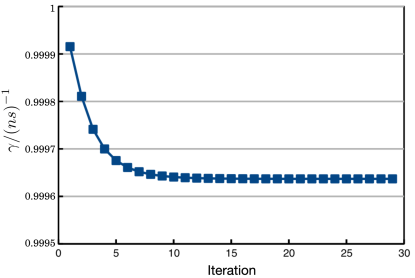
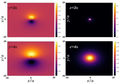
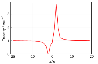
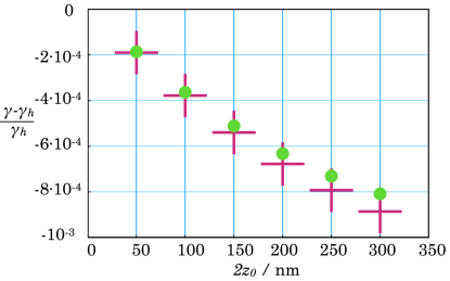
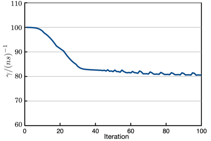
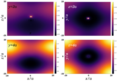
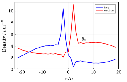
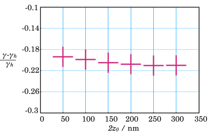
First, we consider the slow recombination regime when the probability of recombination centers is low. This is the case when for our chosen size of the cluster we take in Eq. 14. This corresponds to the case when the diffusion-related charge travel time over the system length is shorter than the recombination time . For the electron and hole the diffusion coefficients we find ns-1 for electrons and ns-1 for holes. To represent this case we assume that the homogeneous recombination rate parameter ns-1. Fig. 1 demonstrates iterative convergence of Eq. 14 towards the solution for this type of system. The convergence is mostly exponential and can be safely truncated after 20-th iteration. The resulting electron distribution is presented in Fig. 2 at the plains , , while along axis at is shown in Fig 3. As expected, the positive trapped charge attracts the electron density, while the negative trapped charge repels it. The distribution becomes rotationally symmetric around axis. It is worth noting that due to relatively large diffusion constants, the distribution is much wider at distances larger than the dipolar charge separation. The integral charge around the dipole (while with low amplitude) makes significant contribution to the recombination process, but the conditions are essentially quite similar to the homogeneous conditions and the effect of the dipolar field of the trapped charges is small. The calculated recombination rates, presented in Fig. 4, demonstrate that while the effect of the dipole is weak, there is still dependence on the separation of charges in the dipole: as the separation is increased, the recombination rate is reduced. This is due to the fact that the electrons and holes become condensed in separate spatial regions so their overlap becomes smaller.
Similar result is obtained for the homogeneous recombination rate 10 ns-1 (100 ps decay time), which also satisfies . Since the rate converges similarly and the distributions obtained are similar to the previous case, we do not present charge distributions. Only the final recombination rates are presented in Fig. 4 by red crosses. We find that the relative dependence on dipole separation is slightly stronger, but still the effect is weak.
Completely different result is obtained when the homogeneous decay is fast: ns-1 (10 ps decay time). In that case we have (for holes) the diffusion term that can be larger or smaller than depending on the amplitude of wave vector . In Fig 5 we show the convergence of the solution. First of all notice additional complexity in convergence. The dependence is non-exponential - the rate evolves in step-like fashion as value traverses specific discrete values of . Due to numerical approach, the result does not relax to the complete stable solution and small fluctuating behavior remains visible. However, the rate can be estimated. For estimation of the rate we take the lower limit, where the solution is mostly stabilized.
Charge distribution becomes more localized compared to the previous case: in Fig. 2 the distribution was homogeneous except at the positions of trapped charges. In the present case in Fig. 6 we find that the long-range charge attraction (due to positive charge) and charge repulsion (due to negative charge) create depleted regions. That corresponds to the situation where the charges recombine faster than they escape the dipolar wells. Very large variations of charge density are obtained along axis as shown in Figs. 6 and 7. The competition between diffusion, recombination and drift can be observed. At the positive defect charge attracts the electron density from the long distances as the Coulomb potential is long-range. This shifts electron and hole distributions along axis in opposite directions so the recombination rate is reduced. Very close to the defect positive charge (at ), while charge density has spikes, the opposite charges are repelled out from the nearest neighborhood and the recombination happens slowly.
Such large variation of electron density has a strong effect on the recombination rate. In Fig. 8 we show that the recombination rate is reduced from the homogeneous case by 20% - much larger value compared to Fig. 4. The effect starts from smallest values, while for nm dependence of the rate is almost constant.
V Discussion and conclusions
Presented model allows determining the effect of internal defect cluster fields on the recombination rate (or time). The model allows to assign a decay rate constant to the highly non-stationary charge distribution decay process. This becomes possible by using the finite box with periodic boundary conditions (-space solution). The approach, thus, allows to characterize the vicinity of the defect cluster. Considering the cluster without periodic boundary conditions it would be impossible to obtain a single rate constant by this method because the system would be described by non-exponential decay process as the decay rate close to the cluster and far from it are essentially different. So the present model is approximate while allows to demonstrate the effect that local fields induce on the recombination process.
According to the presented calculations, the most significant parameter describing charge evolution and recombination in the defect cluster is the diffusion coefficient. It relates the diffusion length and diffusion time via relation . By taking the diffusion time to be equal to the lifetime, we obtain the total diffusion length, i. e. the distance a charge can traverse during its lifetime by diffusion. The total diffusion length is the parameter that should be correlated with the size of the defect cluster. In our analysis we used a box with edge length 1 . If the total diffusion length is much longer than the defect cluster size, the charge will be able to escape the cluster (and the Coulomb field of the dipole): the cluster will have negligible effect on the charge recombination. Diffusion constant for holes in silicon are of order of cm2/s (m)2/s, consequently, the hole covers (m) before recombination takes place if the recombination time is ns. In this case, if the defect cluster extends only over few hundred nm as it was assumed in simulations, its effect on the recombination is almost vanishing, as is observed in Fig. 4. In the other limit, if the lifetime is short - few ps, the total diffusion length corresponds to few tens of nm and that becomes comparable to the size of the defect cluster, and the effect of the cluster dipolar field on the recombination time becomes considerable.
Defining the size of the defect cluster is also not trivial. As Coulomb potential is long range, size of the cluster does not necessarily corresponds with the distance between point defects in the cluster. For the dipolar internal fields, the Coulomb potential energy of the dipole decays approximately as , where is the distance from the dipole. Comparing the cluster-induced Coulomb potential energy (last two terms in Eq. 7) to we can define the effective dipolar capture distance, and the corresponding cluster size , where is the separation of dipolar charges. In our model for dipole charge separation of nm and we can find nm. The relevant size of the cluster that should be considered for the diffusion process is therefore even smaller than we have discussed above.
In this discussion we are not restrictive about homogeneous system recombination rate. The silicon crystals are never pure and various types of impurities create recombination centers. The homogeneous recombination rate therefore varies in various crystal preparation conditions. Additionally, in order to isolate the effect of dipolar fields we neglected the possibility that HE irradiation which creates trapping centers (responsible for creation of internal fields), also generates additional recombination centers in the same area. The local “homogeneous” recombination rate in the vicinity of the defect clusters therefore could be quite different compared to the bulk values of unaffected silicon. Therefore, high recombination rates in the vicinity of clusters and strong influence of the internal cluster fields on the recombination process is highly probable.
Diffusion process is quite easy to evaluate and estimate, while the drift force depends on various additional parameters: the amount of trapped charge, , effective separation of dipole charges (which could be associated with the size of the defect cluster, as discussed above). Consider holes as their diffusion constant is smaller. The quantity , which scales the Coulomb fields in Eq. 9 (notice that ) and equal to with and at room temperature has the dimension on . Parameter has the same dimension and can be directly compared. Taking the smallest we find . Diffusion coefficient of electrons is even larger. The Coulomb drift forces acting on electrons and holes are thus considerably weaker than the diffusion-related gradient forces (including the large dielectric constant). This demonstrates that the diffusion process is extremely fast in Si compared to microscopic internal field-induced gradient forces due to trapped charges by defect clusters. Additionally it should be taken into account that the Coulomb field is long-range but quickly decays on small scale. The thermal activation energy overcomes the Coulomb attraction energy for trapped charge at a distance of nm, hence, only at such small distances the mobile charges cannot escape the potential well of trapped charge. In our modeling the box size is m, consequently, the large amount of charge is barely affected by Coulomb attraction forces.
However, this study of a single dipolar internal field applies when defect concentration is relatively small. If the defect concentration is high, the internal fields are no more dipolar, bulk properties like mobility, diffusion constant, effective masses may be extensively affected. As the parameters become different, the eventual recombination rate can be strongly affected. However, our model with the bulk diffusion constant being independent on the defect concentration allows to highlight how the dipolar internal field redistributes the mobile charges so that charge recombination becomes altered solely due to internal field effects.
Considering realistic samples we should keep in mind that high energy irradiation creates clusters of defects with various configurations of trapped charges. In Figs. 4 and 8 we demonstrated how the rate of recombination changes with the simplest model of trapped dipole. When the distance between trapped charges increases, the whole picture would finally reflect the case of independent positively and negatively charged point defects scattered in the bulk. Since the governing parameter is the diffusion length of a charge, the transition to independent charged defects is directly related to the total diffusion length.
The homogeneous recombination rate, that we consider in our simulations is barely observable quantity in experiments due to variability of types of recombination centers in irradiated silicon. As we have demonstrated the large effect of the dipolar field on recombination rate emerges when the diffusion length is comparable with the dimension of the defect cluster. This can be achieved when the size of the defect cluster is large. As we have discussed, for the recombination rates of s, the effective diffusion length is m. If the defect clusters are of the same dimensions we will have conditions that the charges cannot escape the internal defect fields during their lifetime and the defect cluster is the determining factor governing the recombination rate. Theoretically this is easily demonstrated by making order-by-order solution of the dynamic equation as demonstrated in Appendix A. When the dimensions of the cluster become comparable to the diffusion length (by varying parameter ) the effect is amplified as difference can get to zero in the denominator. Our results thus demonstrate that the ratio of the charge diffusion length and the size of clusters is the most important parameter that governs the sensitivity of the recombination rate to the defect density.
Having this in mind, consider the case of independent homogeneously distributed monopole trapped charges without clasterization, e. to the case where defects are organized into clusters, i. e. finite. Figures 4 and 8 have to be compared starting from large and going to smaller values. We then observe increasing recombination rate with dipolar-type cluster formation. That is how the present model should be conveyed. Totally pure semiconductor crystals do not exist and recombination usually takes place via point defects even before irradiation. In that case, the uniform distribution of point defects would yield the homogeneous recombination rate of such sample . This parameter is essentially proportional to the density of the recombination defects, , while a single defect is characterized by a charge capture radius, . Irradiation of semiconductor by HE particles creates clusters of defects with additional recombination centers and trapping centers. Since no foreign atoms are introduced, additional recombination defects are of the same type as the original recombination defects, while their density is larger in the clusters. We therefore should expect increase of in the vicinity of the clusters, i. e. we can consider the “homogeneous” recombination rate to take very different values in various spatial positions.
Another questionable point is whether bulk crystal parameters should be applicable to the defect clusters. Charge mobility in Si decays with the concentration of dopants (down to 100 cm2/Vs for electrons when defect concentration reaches cm-3)[21]. While overall concentration of defects may not be very high, local concentration in the vicinity of defect cluster may be very high. As we have discussed the lower diffusion coefficients means that variation of the recombination rate at the cluster could be appreciable even at low homogeneous relaxation rates . Our simulations thus correspond to the limiting case when density of defects inside the cluster is low. We find that internal electric field of the cluster becomes playing considerable effect at high concentration of point recombination centers. If we assume that the charge mobility decreases tenfold, the concentration of point recombination centers can be ten times lower to observe the same strong effect. Electron mobilities of 100 cm2/Vs corresponds to the lower limit and thus should represent the case when electrons diffuse over the point defects via tunneling. So these conditions would correspond to the high concentration of trapping centers and that would reflect the other limiting case. However, in the conditions of high concentration of defects the structure of internal fields should be also considered more complicated.
It should be stressed that such clustering of defects may be important for various types of semiconductor high energy irradiation sensors. Defect clustering creates local internal fields and conditions that are different from the bulk. If they determine the bulk properties (e.g. by creating sinks of charge density) this will be observed by bulk experiments.
Concluding, we have presented theoretical analysis of charge recombination in Si crystal in the vicinity of trapped charge creating dipolar field starting from the real space Fokker-Planck equation which describes charge evolution including diffusion and drift forces as well as charge recombination. Using the reciprocal space representation we have the governing equation in the compact form, what allows iterative solution of the equation. Using the stationary conditions we define the experimentally observed recombination rate of the homogeneous system. We found that for slow recombination process in the case of homogeneous conditions, inserting dipolar field minimally affects the rate of homogeneous recombination. Large variation of the recombination rate occurs when the homogeneous recombination rate is fast (on the order of tens of picoseconds). The reason behind this effect is that the diffusion length of charges during their lifetime becomes comparable to the extensions of defect clusters.
Appendix A Order-by-order solution
In order to demonstrate the sensitivity of the effect on various parameters it is instructive to perform analytically few steps. Hence, take Eq. 14 and start from the homogeneous distribution
| (19) |
The first iteration starting from homogeneous distribution we find an additional term in distribution function at :
| (20) |
which gives the recombination rate
| (21) |
We thus find that at first iteration we obtain correction to the recombination rate. Notice that if . However, the situation may become different if as in the case of Si crystal. In that case the integral may yield negative value if . In this case the overall recombination rate may possibly become larger than .
Acknowledgements
This work was performed in the framework of the CERN RD50 collaboration. It was funded by the Lithuanian Academy of Sciences, grant No CERN-VU-2021-2022. Computations were performed on resources at the High Performance Computing Center, “HPC Sauletekis” in Vilnius University Faculty of Physics.
Author Declarations
The authors have no conflicts to disclose.
Data Availability
The data that support the findings of this study are available from the corresponding author upon reasonable request.
References
- Hartmann [2017] F. Hartmann, Evolution of Silicon Sensor Technology in Particle Physics, 2nd ed. (Springer, 2017).
- Moffat et al. [2018] N. Moffat, R. Bates, M. Bullough, L. Flores, D. Maneuski, L. Simon, N. Tartoni, F. Doherty, and J. Ashby, Low Gain Avalanche Detectors (LGAD) for particle physics and synchrotron applications, J. Instrum. 13, C03014 (2018).
- Lindström [2003] G. Lindström, Radiation damage in silicon detectors, Nucl. Instruments Methods Phys. Res. Sect. A Accel. Spectrometers, Detect. Assoc. Equip. 512, 30 (2003).
- Gallrapp et al. [2017] C. Gallrapp, M. Fernández García, S. Hidalgo, I. Mateu, M. Moll, S. Otero Ugobono, and G. Pellegrini, Study of gain homogeneity and radiation effects of Low Gain Avalanche Pad Detectors, Nucl. Instruments Methods Phys. Res. Sect. A Accel. Spectrometers, Detect. Assoc. Equip. 875, 27 (2017).
- Radu et al. [2015] R. Radu, I. Pintilie, L. C. Nistor, E. Fretwurst, G. Lindstroem, and L. F. Makarenko, Investigation of point and extended defects in electron irradiated silicon - Dependence on the particle energy, J. Appl. Phys. 117, 164503 (2015).
- Centoni et al. [2005] S. A. Centoni, B. Sadigh, G. H. Gilmer, T. J. Lenosky, T. Díaz de la Rubia, and C. B. Musgrave, First-principles calculation of intrinsic defect formation volumes in silicon, Phys. Rev. B 72, 195206 (2005) .
- Aye et al. [2021] M. M. Aye, E. Rivasto, M. Z. Khan, H. Rijckaert, E. Salojärvi, C. Haalisto, E. Mäkilä, H. Palonen, H. Huhtinen, I. Van Driessche, and P. Paturi, Control of the nanosized defect network in superconducting thin films by target grain size, Sci. Rep. 11, 6010 (2021).
- Newman [1982] R. C. Newman, Defects in silicon, Reports Prog. Phys. 45, 1163 (1982).
- Leung et al. [1999] W.-K. Leung, R. J. Needs, G. Rajagopal, S. Itoh, and S. Ihara, Calculations of Silicon Self-Interstitial Defects, Phys. Rev. Lett. 83, 2351 (1999).
- McCluskey and Haller [2018] M. D. McCluskey and E. E. Haller, Dopants and Defects in Semiconductors 2nd Edition, 2nd ed. (CRC Press, 2018).
- McCluskey and Janotti [2020] M. D. McCluskey and A. Janotti, Defects in Semiconductors, J. Appl. Phys. 127, 190401 (2020).
- Cottom et al. [2016] J. Cottom, G. Gruber, P. Hadley, M. Koch, G. Pobegen, T. Aichinger, and A. Shluger, Recombination centers in 4H-SiC investigated by electrically detected magnetic resonance and ab initio modeling, J. Appl. Phys. 119, 181507 (2016).
- Alkauskas et al. [2016] A. Alkauskas, M. D. McCluskey, and C. G. Van de Walle, Tutorial: Defects in semiconductors—Combining experiment and theory, J. Appl. Phys. 119, 181101 (2016).
- Ža̧sinas and Vaitkus [2016] E. Ža̧sinas and J. V. Vaitkus, Disordered small defect clusters in silicon, Lith. J. Phys. 55, 330 (2016).
- Huhtinen [2002] M. Huhtinen, Simulation of non-ionising energy loss and defect formation in silicon, Nucl. Instruments Methods Phys. Res. Sect. A Accel. Spectrometers, Detect. Assoc. Equip. 491, 194 (2002).
- Vaitkus et al. [2021] J. V. Vaitkus, A. Mekys, and Š. Vaitekonis, Electron mobility dependence on neutron irradiation fluence in heavily irradiated silicon, Lith. J. Phys. 61, 91 (2021).
- Gaubas et al. [2008] E. Gaubas, A. Kadys, A. Uleckas, and J. Vaitkus, Investigation of Carrier Recombination in Si Heavily Irradiated by Neutrons, Acta Phys. Pol. A 113, 829 (2008).
- Gaubas et al. [2018] E. Gaubas, T. Ceponis, L. Deveikis, D. Meskauskaite, J. Pavlov, V. Rumbauskas, J. Vaitkus, M. Moll, and F. Ravotti, Anneal induced transformations of defects in hadron irradiated Si wafers and Schottky diodes, Mater. Sci. Semicond. Process. 75, 157 (2018).
- Breuer and Petruccione [2007] H. P. Breuer and F. Petruccione, Theory Open Quantum Syst. (Oxford University Press, 2007).
- Ashcroft and Mermin [1976] N. W. Ashcroft and N. D. Mermin, Solid state physics (Thomson Learning Inc., 1976).
- Arora et al. [1982] N. Arora, J. Hauser, and D. Roulston, Electron and hole mobilities in silicon as a function of concentration and temperature, IEEE Trans. Electron Devices 29, 292 (1982).