A review on steeply inclined settlers for water clarification
Abstract
Steeply inclined settlers (SIS) are solid-liquid separators that feature close, inclined confining elements that allow significant settling enhancement when compared to vertical tanks, resulting in relatively low footprints at equal throughput. The present article reviews the working principle, flow configuration, capacity, and several technological advances related to this kind of equipment. The consistency of the Ponder, Nakamura and Kuroda theory, developed after the discovery of the Boycott effect in 1920, which is essential to the settling enhancement effect, and the engineering approach developed independently for the design of SIS settlers during the late 1960’s, based on particle trajectory analysis, is established. A discussion about potential developments for future improvement of the technology is made, with emphasis on three main topical areas: improvements of settling element array, optimization of inlet conditions, and potential improvements of the design of settling elements. The application of the technology to the mining industry is discussed in the context of increasing water scarcity and the progressive ore grade decrease.
keywords:
lamella settlers, high-rate settlers, super settlers, inclined plate settlers, tailings, water, clarification, mineral processing1 Introduction
Water footprint has become a central issue in mineral processing plants and is inherently related to the sustainability of the mining industry. The progressive intensification of water recycling processes and the projected spreading of mineral concentrator plants using saltwater (Ihle and Kracht, 2018) in a context of progressively decreasing ore grades (Northey et al., 2014) imply a challenge not just to mineral recovery (Rao and Finch, 1989), but also to water recycling from tailing stream operations as well as related processes such as solid handling infrastructure because of factors including complex rheology issues (Merrill et al., 2017; Contreras et al., 2020) and long distances connecting sources and destinations for such increasingly fine and concentrated slurries (Ihle, 2014). Tailing systems, and in particular, their storage facilities, are presently the center of attention of the mining industry due to their implications on environmental impact (Lottermoser, 2010) and even the safety of the increasing number of people living in their surroundings (Franks et al., 2021). Their mineral characteristics exhibit strong variability, both between mining operations (Bulatovic et al., 1999) and within them (Tungpalan et al., 2015), which is inherited to slurry and suspension properties, including settling velocity of the fine contents and the rheological properties of both the slurries and the sludge at the underflow of settling unit processes. Water recovery in mineral processing is mostly made in thickeners, which in most cases work indeed as thickener-clarifier units (Concha, 2014; Arjmand et al., 2019). Thickening and clarification operational optima are not necessarily the same, and control measurements focused solely on setting a specific underflow concentration may not meet those to ensure minimum turbidity of the overflow (Castillo et al., 2019). Castillo et al. (2019) confirmed the central role of turbulence intensity on the quality of the overflow, even without the addition of reagents other than those use in the previous (thickening) stage. The potential to detach thickening and clarification thus offers an opportunity to fine-tune both processes separately and may report benefits including process stability and reduced overall flocculant consumption.
Steeply inclined settlers (named hereafter as SIS) are low-footprint, gravitational solid-liquid separators suitable for clarification purposes used either as stand-alone unit processes or in combination with others depending on the nature of the suspensions to be treated. They feature closely spaced sloping sections (either plates or conduits), with typical angles, measured from the horizontal, between and (Smith and Davis, 2013), plate separations or conduit hydraulic diameters typically of a few centimeters (in some cases, below ) and section lengths of about (Wilson, 2005; Tarleton and Wakeman, 2007) thereby confining otherwise homogeneous solid-liquid feeds and enhancing the separation rate when compared to vertical ones such as clarifier tanks111Low inclination settlers, also referred to as essentially horizontal, whose slight tilt (on the order of a few degrees from the horizontal) is primarily to facilitate backwash operations (Culp et al., 1968), are excluded from the present definition of SIS.. Belonging to the class of so-called high-rate settlers, SIS technology is most commonly used for water clarification purposes to remove turbidity from water, commonly in combination with coagulation and flocculation as pre-treatment operations, thus proving a cost-effective solution for secondary treatment in wastewater plants (Jiménez and Ramos, 1997; Clark et al., 2009; Edzwald, 2010). A 2005 survey reveals an installed clarification capacity using this working principle of over 4.1 million , with extensive application in France (Wilson, 2005). Such a survey does not include China, but Zhou et al. (2012) point out the incorporation of several dozens of lamella thickeners.
In the mining industry, the increasingly widespread appearance of clays in gangue minerals tends to hinder recycled water quality (Connelly, 2011; Gräfe et al., 2017). SIS technology is a low footprint, natural option for secondary treatment of turbid water to decouple the thickening function from the overflow cleaning process objective in otherwise thickener-clarifier units. This additional process flexibility becomes increasingly convenient both from a process perspective and from an economic one, considering that increased dosing of high molecular weight flocculants (Connelly, 2011), or additional dilution prior flocculation when compared with tailings without significant content of such gangue minerals (Gräfe et al., 2017), might be required in the presence of clays. Although the use of SIS equipment is not new to the mining industry (see, e.g., Fuerstenau and Han, 2003; Metso, 2021; Parkson, 2021; Westech, 2021), a comparatively small number of large-scale mineral processing plants use this technology and mostly rely on thickeners to control overflow water turbidity. An additional advantage of splitting thickening and clarification refers to underflow handling: separating fine solids from the bulk of the thickener underflow also splits the concentrated slurry problem into one which is massive in throughput but with comparatively coarser material and a second one (coming from the clarifier underflow) which, in spite of being a fine slurry (and thereby potentially complex), would most likely have a significantly smaller throughput than that of the plant feed stream.
The present article focuses on SIS fundamentals and reviews advances on the knowledge of its working principle and related technology development. A discussion on the opportunities to increase the quality of overflow water in mineral processing plants using SIS equipment is made. The present perspective article complements relatively recent and more general reviews on gravity concentration and classification in mineral processing (Tripathy et al., 2015; Das and Sarkar, 2018; Galvin, 2021).
2 Overview
2.1 Historical background
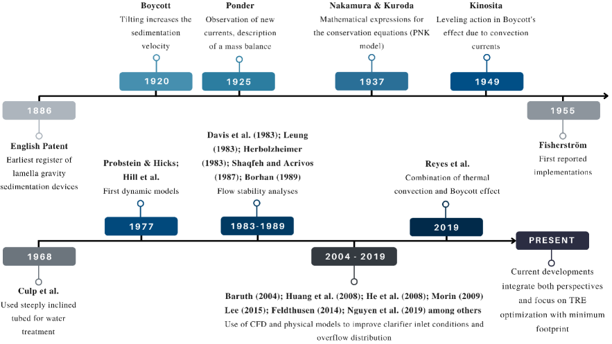
The development of SIS has the peculiarity of being studied from two different outlooks in parallel: a theoretical-experimental perspective and an industrial perspective (see Figure 1). The earliest record of the enhancement of settling efficiency by wall inclination was due to the British pathologist Arthur Edwin Boycott. Over 100 years ago, he discovered that the settling of red blood cells was enhanced by tilting test tubes from an otherwise upright position. In a brief letter to Nature (Boycott, 1920), he reported the proportions of clear serum after 5 hours of settling indicated in Table 1, where faster settling was found at a tilt angle (measured from the horizontal). His tentative explanation of the phenomenon, based on an angle-dependent hindrance of sedimentation by Brownian motion, was not correct. Subsequent researchers would identify the release of clear fluid below the upper wall as the main mechanism in the increased sedimentation rate (Ponder, 1925; Nakamura and Kuroda, 1937; Kinosita, 1949), which would later be convincingly confirmed by Hill et al. (1977, see also further references therein). Nevertheless, Boycott’s observation was the first step on what would be afterwards a whole research line both in fluid dynamics and process engineering, the so-called Boycott effect, which is essential to SIS technology.
| Tube diam. | Inclination from the horizontal | |||
| (mm) | ||||
| 2.7 | 6 | 20 | 29 | 51 |
| 8 | 5 | 10 | 15 | 21 |
| 14 | 4 | 5 | 9 | 12 |
In the water treatment industry, Boycott’s discovery remained seemingly unnoticed for decades. While the earliest invention related to inclined plate separation appears to be an English patent from 1886 (Forsell and Hedström, 1975; Baruth, 2004), the first reported implementations were made in Sweden in the 1950’s (Fischerström, 1955; described by Hendricks, 2006), and the earliest engineering approaches to the design of tubular SIS date to about a decade later (Culp et al., 1968). With emphasis on reducing clarification equipment footprint (Edzwald, 2010), these advances were inspired by earlier theories advocating the use of shallow settling basins to increase the capture surface (Hansen and Culp, 1967; Hendricks, 2006). This focus on increased sediment capture by the upward-facing plate can be contrasted with the earlier explanation of the Boycott effect, mentioned above, of increased release of clear fluid below the (downward-facing) upper wall; while not equivalent (Hill et al., 1977), it will be shown that these two points of view are consistent and can under some conditions yield the same result. This difference in perspectives is a sign that, as it would remain the case for much subsequent work (e.g., De, 2017, and references therein), those first attempts were developed without any mention of Boycott’s finding or subsequent research addressing the increase in clarified liquid production under inclined walls. In fact, the high sedimentation rate observed for high inclination angles came as a surprise along another key advantage of SIS. As summarized by Culp et al. (1968), “an angle of 60 deg provides continuous sludge removal while still allowing the tube to function as an efficient sedimentation device.”(emphasis added). The down-sliding of the concentrated settlement opens the way to sedimentation processes in continuous operation.
2.2 Operation fundamentals
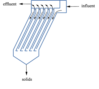
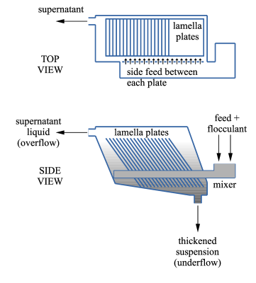
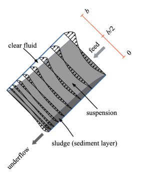
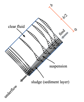
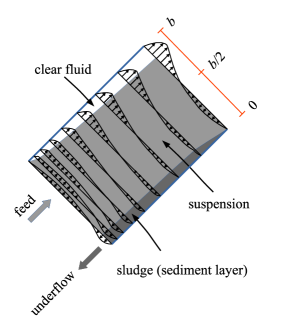
As advanced above, the operation of SIS can be classified according to whether the clarifier is open or closed (i.e., whether it operates in continuous or batch mode). Industrial operation of SIS equipment is mostly continuous (see, e.g., Edzwald, 2010, for the case of the water treatment industry). In continuous operation, SIS are also classified mainly as countercurrent or cocurrent, but also possibly as cross-flow, according to the relative position between the feed and the underflow. While in countercurrent equipment the feed is located at or close to the bottom (the most common configuration in SIS equipment, Wilson, 2005; Crittenden et al., 2012), in cocurrent ones the feed is at or near the top (its use has been suggested for low concentration, network forming flocs by Forsell and Hedström, 1975).
Figure 2 shows a perspective view of a Lamella separator (Nordic Water, 2021), designed to operate in countercurrent configuration. It can be seen that the feed is located at the lowest portion of the array of inclined plates (the inlet openings on the sides), setting a clear fluid flow moving upwards (towards the overflow collection flumes) with a direction opposing to that of the sludge (moving downwards and collected in a hopper for subsequent discharge and transport). Figure 3 shows diagrams of the other two possible configurations of this kind of equipment, namely cocurrent and cross-flow. In the cocurrent configuration (Figure 3a), the feed enters either at the top or at some intermediate point in the length of the settling element towards the bottom (underflow), without a net sideways component. In the cross-flow configuration (Figure 3b), there is an overall component of the flow that crosses settling elements sideways, where there is a countercurrent component due to the fact that the feed is below the overflow.

| (a) |
 |
| (b) |
 |
Inherent to the concept of SIS technology is the existence of inclined confining elements. They can be plate-like, thus defining lamella (also named inclined plate settlers or IPS, Forsell and Hedström, 1975) compatible with the cross-flow configuration, or have closed settling elements forming an array of conduits of square, rectangular, hexagonal, circular, or Chevron-like (V-shaped) cross-section conduits. Such packs of settling elements do not need to be set in a single direction, and there are cases where arrays of alternating direction sections are built, which can provide additional stability to the settler (Letterman et al., 1999). The referred characteristic of an array of settling elements makes, at equal throughput, their footprint considerably smaller than that of vertical equipment. Examples of such differences in footprint and performance are numerous, including Wenk (1990), who reports, in the case of the phosphate industry, the use of of an otherwise vertical settler footprint at an equally effective settler area. In the context of low-cost technology utilization for turbidity removal of drinking water, Wisniewski (2013) reported a footprint reduction up to compared to a vertical tank. Also using plate-like elements, the numerical simulations of Tarpagkou and Pantokratoras (2014) revealed an overall differential increase of in settling efficiency, adding a lamella settler bank to an existing primary settling tank. More recently, Wang et al. (2020) report a threefold increase in fine sediment removal efficiency of an array of inclined tubes compared with a vertical tank.
3 Characteristics of steeply inclined settlers (SIS)
3.1 Surface overflow rate (SOR)
SIS technology excels in its low footprint when compared to other technologies for the same purpose. Key performance parameters of this technology are the surface overflow rate (SOR222To this purpose, the term surface loading is also used in the literature.) and the effective surface area (). They are defined, in terms of the geometrical parameters defined in Figure 4:
| (1) |
where is the total overflow rate (in volume/time) and are the length and width of the plate, respectively, and is the number of vertical arrays of plates placed sideways. In other words, is the total horizontally projected area of the settling system. Given a particular settler geometry and the characteristics of a suspension (including its temperature, see Takata and Kurose, 2017, for a discussion), the particular value of the SOR (determined also by the inflow rate) will affect what part (or possibly ) of the suspended solids will be removed. In terms of engineering design guidelines, Table 2 shows recommendations regarding SOR values for different types of sediments.
| Reference | Type of particle | Recommended SOR (m/h) |
| Driscoll et al. (2008) | Mill scale and pulp, paper solids (light particles) | 0.6 |
| Mill scale and pulp, paper solids (heavier ones) | 2.4 | |
| Crittenden et al. (2012) | Alumn flocs ( ) | 2.5 - 6.5 |
| Water treatment (heavier flocs) | 3.8 - 7.5 |
Similar ranges are given elsewhere in the literature (e.g., Wilson, 2005; Davis, 2010). When microsand particles are added between downstream coagulation and upstream flocculation, SOR values can be enhanced to typical values between and for clarification in water treatment processes (Baruth, 2004).
3.2 Settler capacity for monodisperse suspensions
For suspensions that can be considered in practice as monodisperse, a criterion for the definition of settler capacity is to find the conditions that will ensure that particles will not report to the overflow of the settler. Although the condition of ensuring zero turbidity might be impractical (and should be, in most cases, replaced by the notion of efficiency as described in the next section), the present section uses this condition to develop and put together two possible approaches for capacity estimation of SIS.
3.2.1 Mass balance approach
Batch case
In batch (closed) systems, a first explanation of the observed clarification mechanism of inclined tubes compared with vertical ones is attributed to Ponder (1925) and Nakamura and Kuroda (1937). This, so-called PNK theory, states that effect of particle settling beneath an inclined, downward facing wall, is to convey additional clear fluid upwards, above the existing horizontal suspension-supernatant interface. This, by virtue of mass conservation, causes that such suspension-clear fluid interface moves downwards at a faster rate than that occurring in vertical conduits. A geometrical interpretation conducting to the PNK expression (derived hereafter) is reviewed in Kinosita (1949) and Hill et al. (1977).
Consider a tilted, closed rectangular domain as depicted in Figure 4. Initially, the volume is filled with a monodisperse, homogeneous, and dilute suspension (volume fraction ) of spheres of diameter and density , between vertical coordinates and , and where the fluid phase has density and dynamic viscosity . Immediately after the start of the experiment, an interface between the suspension and a supernatant layer forms due to the settling process. As the interface descends, its vertical displacement is traced, at each time by the vertical level at which this interface reaches the lower wall, which can in turn be obtained from a solid density function describing the spatial distribution of the suspension, as shown by the gray area in Figure 4. It is assumed that, away from the interface between the suspension and the clear liquid, the solid-phase velocity , where is the unit vector in the direction of the gravity acceleration, , and . This is the settling velocity of the bulk suspension, which depends on the solid and fluid phase properties, the settling element equivalent diameter, and the particle concentration. In the case of a single sphere settling in an otherwise quiescent Newtonian fluid and in the limit of small Reynolds number, then is the Stokes velocity
| (2) |
More generally, is commonly expressed as , where and (Davis and Acrivos, 1985). A consequence of the dilute hypothesis is that the sediment layer, where particles accumulate along the lower wall, is very thin and is assumed herein of negligible thickness.
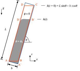
We define the control volume ABCD of Figure 4, wherein the segment BC is located slightly above the lower wall, say a few particle diameters, just enough so that the negligibly thin sediment layer is left outside of the control volume. The opposite segment DA coincides with the location of the upper wall.
Unless transient behavior occurs when slender containers are used to further accelerate the process (Herbolzheimer and Acrivos, 1981), the interface has been observed to remain mostly horizontal (Kinosita, 1949; Acrivos and Herbolzheimer, 1979), leaving, as it evolves, a clarified layer above. A density function can be defined within the control volume as (Ihle and Reyes, 2022):
| (3) |
where the time-dependent position of the top of the suspension layer ( in Figure 4), is assumed as a horizontal line at the vertical level Differently from the referred, previous geometric interpretations, this specific choice of control volume is independent of the thickness of the clear fluid layer beneath . Imposing solid phase conservation and using the Reynolds transport theorem (, where is the unit normal pointing outwards , and represent the control volume and its boundary, respectively), the well known PNK expression is obtained:
| (4) |
where the first and second terms in the right hand side are given by the fluxes through AB and , respectively.
This model has been subject of experimental scrutiny, and differences with the theory have motivated to propose ad-hoc adjustments. Graham and Lama (1963) proposed to include a concentration- and geometry-dependent correction factor (between and ), and their results were sensitive of the inclination angle for values above and to particle concentration in the whole range tested. The placement of a factor multiplying the whole right hand side of (4) caused some scatter in their results. Vohra and Ghosh (1971) proposed to modify the location of such correction to solely multiply the term including in (4) (linearly increasing with particle concentration and inclination-independent at low concentrations). Similarly, for the case of settling in inclined tubes, Sarmiento and Uhlherr (1978) also proposed a correction factor () to the second term based on the possibility of a horizontal component of the liquid phase flow feeding the clarified layer from the suspension. According to their experimental measurements using lightly flocculated red mud suspensions ( smaller than ), they proposed a factor of the form , which depends strongly on the suspension characteristics. To explain the discrepancies between experimental results and the PNK model (4), Oliver and Jenson (1964) relaxed the original mass-balance assumption that the clarified liquid volume below the upper plate reports instantaneously to the overflow. Instead, part of the water in the suspension below the top plate flows into the clear water layer accumulating as it ascends, resulting on a wedge-like clear fluid layer shape. The results of their batch model had best fit at relatively low concentrations and small times; although they report some degree of wave formation, they observed that most of the settling process was in the absence of such disturbances. The discrepancy between the PNK model and experimental results has been explained by Zahavi and Rubin (1975) by the suspension concentration. In their experimental and theoretical work, they found that enhanced settling in vessels with inclined walls accentuates with concentration (they tested with volume fractions below ) and that discrepancies with the PNK model are partly due to changes in concentration during the settling process, not accounted for in the original model. A different approach was performed by Acrivos and Herbolzheimer (1979), who provided a fluid dynamic derivation of the PNK model for containers of general shape and discussed the conditions for its validity, placing the PNK model on a firmer theoretical basis. On the other hand, they explicitly related the PNK model for batch clarifiers to the continuous settling process and highlighted the importance of the stability of the interface as a key limiting factor of the PNK model’s applicability.
Continuous feed
For batch clarifiers, the rate of production of clarified fluid volume (per unit length in the spanwise direction), is obtained from the vertical velocity of the interface (4) and the horizontal size of the container as . In terms of the more commonly used distance along the lower plate between the edge and the suspension height , , given by (Figure 4), the production rates becomes
| (5) |
The batch-PNK theory result (4) can be extended to countercurrent, steady-state continuous mode of operation, noting that the required feed required to keep the supernatant-suspension boundary at the height corresponding to length (constant) must satisfy where is the mean velocity along the settler, and thus (Davis and Acrivos, 1985):
| (6) |
with . The volume flow per unit width has been identified by Herbolzheimer and Acrivos (1981) and Leung and Probstein (1983) as (approximately) the maximum theoretical feed capacity of a tube or plate settler in the case when the clear fluid layer is thinner that the suspension layer (see Section 4.1, below) or countercurrent flow, and approximately corresponds to (6) when and . It is noted that while in vertical tubes (), the critical particle removal condition is achieved with (i.e. the mean flow velocity is equal to the settling velocity), in inclined tubes, depending on and , could be much larger than the unity (in other words, the settler would separate particles at mean flow velocities largely exceeding the particle settling value), thereby denoting the significant increase of the capacity of the settler that results from inclining conduits.
According to Equation (5), the clarification rate increases with the aspect ratio , but there is a limit regarding real operational conditions that may cause the occlusion of very thin elements. Commonly, industrial inclined elements (e.g., tubular) in the wastewater industry feature between close to 50 (see Section 1) and larger than 100 in some other applications of mineral processing (Galvin, 2021). Limitations found in the wastewater industry that deals with flocs, e.g. made of clays or other ultrafine particles, are the potential of clogging for tubular elements below in diameter (Lin, 2014), a problem that has also been known for plate-like equipment (Zhou et al., 2012). The potential of clogging, has been mostly controlled adjusting the incline angle of cells (Culp et al., 1968) or exerting vibration either to the cell or to the suspension, as discussed in Section 5.1.
In the theoretical analysis made by Herbolzheimer and Acrivos (1981) and Leung and Probstein (1983), there is no specific regard to the tubular geometry in their derivation, and the corresponding settling elements used in their experiments were indeed rectangular with the longest side placed vertically. So far the only exceptions using the PNK theory are the derivations in the batch case by Graham and Lama (1963), who replace in (4) by , with the inside diameter of the pipe, and the recent generalization by Ihle and Reyes (2022), both for batch and continuous geometries, referred in Section 3.2.2.
3.2.2 Particle trajectory approach (continuous feed)
If particles are smaller than the smallest flow scale and their inertia can be neglected, then a force balance on a single sphere of volume yields
| (7) |
where is the drag force acting on the particle, and is the local pressure gradient in the fluid phase. The last term comes from the pressure integral assuming that pressure variations on the particle surface are given by the hydrostatic approximation. Noting that the drag force occurs on particles per unit volume (with the volume fraction) and that , then
| (8) |
where is the volume force density exerted on the fluid phase by the particles. In other words, such volume force corresponds to the immersed weight of the particles. An implication of (7) and the hydrostatic assumption is that particles instantaneously adopt a terminal velocity. If particles are spherical and is their diameter, from the integration of the flow equation around a sphere, in the limit of small particle Reynolds number, the drag force is (Stokes, 1851, eq. 126), where and are the solid and fluid velocities, respectively. Therefore, the solid phase velocity must verify:
| (9) |
with given by (2). Thus, this expression provides a relationship between the absolute velocity of the solid phase, the absolute velocity of the fluid phase, and the settling velocity in the dilute limit.
In the wastewater industry, the approach that is most widely referred to for the dimensioning of SIS settling elements (excluding flow entrance length, as modelled by Fadel and Baumann, 1990) is that particles describe a straight-line trajectory starting at any normal coordinate from the bottom plate; this assumes that the system is in the dilute limit, at steady state at each inclined flow conduit, and that the flow is uniform and reasonably well described by the mean flow velocity. While Fadel and Baumann (1990) have argued that the constant velocity model leads to a sub-dimensioning of the tube length, this is still widely recommended in the literature (e.g., Letterman et al., 1999; Wilson, 2005; Crittenden et al., 2012; Lin, 2014; Droste and Gehr, 2019). If, in this case, particles are nearly spherical (and also sufficiently small to render the particle Reynolds number very small), then the form factor in the Stokes drag force expression above can be replaced by a different one provided that their resistance to the flow is isotropic (Guazzelli et al., 2012). If so, the Stokes settling velocity in (9) can be replaced by where, in this case, is an equivalent diameter of the particle, which will depend on its shape (see, e.g., Komar and Reimers, 1978; Hartman et al., 1994; Letterman et al., 1999). Thus, the solid phase velocity can be assumed, using in the right hand side of (9), that:
| (10) |
Defining and as unit vectors parallel and normal to the inclined plate (aligned with the axes and in Figure 5), then the solid phase velocity vector corresponds to:
| (11) |
where is or in cocurrent or countercurrent flow, respectively. Assuming unidirectional fluid phase flow in the direction parallel to the plate, and noting that in light of the present approach, the maximum travel time of a single particle, , can be computed as that corresponding to a particle departing from the top plate (), then (Letterman et al., 1999):
| (12) |

Letterman et al. (1999) used directly in (12). Thus, the plate length in excess of the entry value is computed as:
| (13) |
where is the coordinate normal to the plate. Noting that , the procedure described in Letterman et al. (1999) suggests that the plate length of the settler (in addition to the entrance length, where the flow is not uniform), can be computed using (13) as:
| (14) |
where the corresponding limiting condition for effective separation of particles is expressed as:
| (15) |
It is noted that the countercurrent case () corresponds to the prediction obtained using the PNK model in (6). This implies that, for the particular case of the parallel plate geometry, the present approach is accurate from a mass balance perspective. Also, in the case of the countercurrent case, from (14), it is concluded that , which thereby confirms the maximum throughput conclusion obtained using boundary layer flow arguments (Herbolzheimer and Acrivos, 1981; Leung and Probstein, 1983).
This simplified approach can be applied to a different (constant) cross-sectional area, provided in (12) is replaced by the maximum top-to-bottom distance normal to the flow plane, thereby representing the largest possible travel time of a single particle. For instance, in the case of a pack of regular hexagons of side (Figure 6), the largest travel distance of particles, denoted as the perpendicular line between the top plane and the bottom plane in the figure, is given by . In this example, if the volume flow at each conduit () is known, then the mean velocity can be computed, in the case of the hexagonal cells, as .

Key to the derivation of the criterion (15) is that particles move along the channel with characteristic longitudinal velocity corresponding to the mean flow velocity. Yao (1970) relaxed this restriction including in his analysis the vertical slice of the velocity profile corresponding to the longest vertical settling section (e.g., a central vertical plane in pipe flow), and proceeded with integration to find a condition to ensure that particles will settle in the conduit rather than report to the overflow of the clarifier:
| (16) |
where shares the same definition as in (15) and is a shape factor that results from imposing the boundary conditions of the problem (i.e., at the top and the bottom of the flow slice of interest). Although his calculations were done only for the countercurrent condition, it is possible to formulate them also for the cocurrent case, whereby an analogous expression to (15) can be found. The parameter is defined as:
| (17) |
where is the (permanent, laminar, and independent of the longitudinal coordinate) velocity profile of the vertical slice of height , which is that associated with the maximum particle travel distance. For , particles will not report to the overflow. Yao (1970) computed for the parallel plate geometry, for tubes, and for square conduits. This widely cited approach has also been subject to criticism, being overly conservative (Fadel and Baumann, 1990). Recently, combining mass balance and the concept of falling distance along the conduit resulting in (17), Ihle and Reyes (2022) proposed a new, less conservative criterion that extends the set of cross-sectional geometries originally reported by Yao (1970) and provides additional values of .
Other approaches in the design of settlers have been discussed by Willis (1978), Zioło (1996), and Bandrowski et al. (1997), including asymptotic approaches (i.e., those predicting complete clarification only in the limit ) and a polydisperse formulation that starts from a particle particle size distribution representing that of the suspension, which is used to define a settling velocity distribution (a version of this model, adapted to a lamella settler pack fitted as a settling ring at the overflow of a vertical thickener is proposed by Kowalski, 2004). After a comparison and validation campaign using two independent datasets, Bandrowski et al. (1997), concluded that the model based on a single cutoff settling velocity including (15) (countercurrent flow) and (16) are of comparable accuracy than his asymptotic model and had less deviations from experimental data than others (described by Zioło, 1996) and can yield similar results than those including size distributions.
3.3 Efficiency
In most industrial processes, it is virtually impossible to obtain a particle-free overflow due to equipment and suspension conditions and yet some degree of turbidity is acceptable. In clarifiers with dilute feed, the most widespread process indicator of efficiency in this context corresponds to the turbidity removal efficiency (TRE):
| (18) |
where and represent the turbidity at the feed and overflow, respectively (typically measured in NTU and commonly linearly related with particle concentration with high correlation coefficients, as described by Bertrand-Krajewski, 2004; Saady, 2012, and references therein). Fixing the clarifier and the suspension characteristics, the TRE is most commonly a decreasing function of the feed flow and thus of the SOR. The experimental study of Jiménez and Ramos (1997) with agroindustrial biological flocs shows a linear SOR-TRE behavior both using plates and tubes as SIS elements, with TRE-values above . For storm-water turbidity removal purposes, Clark et al. (2009) report composite data revealing a drop in from – to ca. , associated with a SOR range between and and TRE-values between and . Using in their experiments sand and ground silica, they found a tendency to a decreasing SOR-TRE curve with a stronger scattering in the low flow end. Salem et al. (2011) made experiments using walnut shell particles (density about half of that of natural sediments). Instead of monitoring turbidity, they measured solid concentrations at the feed and the overflow and used a definition of separation efficiency (SE) analogous to (18), finding a relatively low-efficiency range between ca. and testing three designs of settler feeds. In their flow rate-SE determination, they found a tendency to a lower plateau for relatively high feed flows. Although they did not report the flow Reynolds number within the settling elements they used, it is apparent that such low SE-values were found because they configured the flow in their experiments either turbulent or transitional (at least, that was their numerical modeling hypothesis). Saady (2012) studied the problem of clarification of river water with very fine particle contents, an application that resembles the problem of thickener overflow cleaning under the presence of fine particles. Using alum (aluminum sulfate) coagulants, he produced flocs of size distribution finer than ca. and reported turbidity removal efficiencies between about and for SOR values between and , fitting logarithmically-decreasing SOR-TRE curves (in a previous contribution, the same author fitted TRE curves to , with ).
Table 3 presents a comparison of the main parameters of the above discussed reports from previous authors.
| Reference | Type of floc | SOR-TRE curve behaviour | Efficiency (TRE %) |
| Jiménez and Ramos (1997) | Agroindustrial biological flocs | Linear | >80 |
| Clark et al. (2009) | Storm water turbidity removal | Decreasing, strong scattering in the lower flow end | 64-98 |
| Salem et al. (2011) | Walnut shell particles | Tendency to a lower pateau for high feed flows | 24-45 |
| Saady (2012) | River water with fine particles | Logarithmically decreasing | 83-95 |
An alternative means of assessing the performance of the SIS system concerning process characteristics (i.e., how much of the feed can actually separate, which is measured using the TRE parameter) is to compare it with the maximum possible value. This corresponds to the PNK result, which, as has been pointed out, has been noted theoretically to be the maximum attainable throughput (Leung and Probstein, 1983; Davis and Acrivos, 1985) given system geometry and suspension characteristics. Borhan (1989) has defined such overall efficiency as:
| (19) |
where is the maximum possible flow that yields zero turbidity at the overflow, and is the feed volume flow (in this case, per unit width) obtained from (6). As the settling velocity () includes, from an empirical perspective, the effect of particle shape and suspension concentration, the only factor that can render is the development of flow instabilities within the cell. In his experiment on countercurrent (subcritical flow) flow, Borhan and Acrivos (1988) found higher values of after increasing particle concentrations. This was, however, at a cost of clarification rate (), given the reduction of the settling rate due to such increase of concentration. Also, similarly as in Leung and Probstein (1983), he found that higher efficiencies are found at lower inclination angles.
3.4 Connection between SOR and overflow turbidity
Given a settler geometry and suspension characteristics, it has been mentioned above that it is possible that the SOR can be related to the TRE, in a way that increasing overflow rates comes at a cost of increased turbidity. There is, however, a single theoretical maximum value of the surface overflow rate below which there is not particle flow at the overflow (i.e. ), and corresponds to the clarification rate , where is given by (5) and is the number of settling elements of the clarifier. Thus:
| (20) |
In other words, the limiting condition to avoid particle presence at the overflow depends on the settling velocity, which can be regarded as an intrinsic property of the suspension.
4 Flow dynamics in SIS
The research work on the flow dynamics reported during the second half of the 1970s (probably starting with Hill et al., 1977; Probstein et al., 1977) represents an inflection point on the understanding of the underlying physics behind SIS technology and gave birth to a modern approach of modeling this kind of equipment.
Using the dilute limit approximation, Hill et al. (1977) used the same velocity and time scales indicated herein and proposed a set of mixture equations to numerically describe the flow under a cone. This pioneering work concurred with the layered model proposed by Probstein et al. (1977), also based on the dynamic balance in the flow as opposed to the previous kinematic approaches that attempted to correct (4) to describe more realistic conditions (see Oliver and Jenson, 1964; Hill et al., 1977; Acrivos and Herbolzheimer, 1979, for early references in the subject). In particular, Hill et al. (1977) identified a dependence of the flow features with a Grashof and a Reynolds number ( and , respectively), defined as:
| (21) |
and, moreover, the ratio
| (22) |
The Grashof number represents a balance between buoyancy (here, induced by particle settling) and viscous dissipation force, and the Reynolds number a balance between inertial and viscous force. Therefore, represents a balance between buoyancy and inertial force. It is noted that industrial-sized equipment for solid-liquid separation using inclined plates have values of on the order of (Leung and Probstein, 1983). This confirms the pertinence of the boundary layer approximation. The first research that sought to apply the boundary layer concept to describe the details of settling in inclined containers was due to Acrivos and Herbolzheimer (1979). Starting from a dynamic formulation similar to that of Hill et al. (1977) (albeit, correcting both dynamic viscosity and settling velocity with the average effect of particles), they derived and solved a boundary value problem similar to the Falkner-Skan equation (Currie, 2012). They also showed from their fluid dynamic approach that the mass balance statement (4) is valid in the limit of large values of . Their approach, centered on the clarified and the suspension layer was complemented by Schneider (1982) with a drift flux model that identifies feasible suspension-sediment layer combinations according to the suspension concentration-dependent response, by analogy with the Kynch theory of (vertical) thickener-clarifiers, discussed in detail by Concha (2014).
For the case of slender containers, Herbolzheimer and Acrivos (1981) and Leung and Probstein (1983) provide expressions to estimate thicknesses in cocurrent and countercurrent systems. It is noted that, when it evolves very thin compared to the plate spacing and prevails a balance between buoyancy and viscous forces, the clear fluid layer thickness away from the bottom edge of the countercurrent settler is approximately proportional to , where is the longitudinal coordinate measured from the upper plate of the bottom edge (Laux and Ytrehus, 1997, provided a numerical verification of this behavior). A derivation of this exponent using boundary layer arguments is given in A.
In countercurrent flow, a shear stress on top of the sediment layer exerted by the feed (carrying the suspension) is added against the sediment flow direction, which makes common that higher angles than in cocurrent equipment are required to maximize performance (Leung and Probstein, 1983).
The internal flow structure of SIS cells can be summarized conceptually on three layers: (a) A clear layer near the top where all or part of it may report to the overflow, (b) a suspension layer of particle volume fraction equal to that of the feed () that may flow either upwards or downwards, and (c) a sludge layer, flowing downwards, of volume fraction , that results from particle settling within the cell.
The angle of the settler should be sufficient to allow for the sludge to continuously flow towards the underflow. Such condition is the result of complex inter-particle interactions that can be interpreted as an equivalent non-Newtonian fluid, not only in the case of suspensions prone to the effect of physico-chemical properties (Seyssiecq et al., 2003), but also in the simplest, non-cohesive case, defined solely by hydrodynamic forces. While early interpretations of these dense currents modelled particle flow as the result of a diffusion-like process (Kapoor and Acrivos, 1995), a more recent approach embrace equivalent rheological properties in terms of a viscous number, defined as a balance between particle a rearrangement time scale and a strain one, where the relevance of particle inertia is a defining element (Boyer et al., 2011). Examples of slowly flowing, non-colloidal particle gravity currents, interpreted in terms of such viscous number can be found both with negligible confinement in published experimental work (Cassar et al., 2005; Palma et al., 2016) and with strong confinement in the numerical simulations of Palma et al. (2018).
| (a) Cocurrent subcritical | (b) Cocurrent supercritical |
 |
 |
| (c) Countercurrent (subcritical) | |
 |
|
The first non-uniform flow model to estimate the capacity and essential flow features of SIS cells has been reported by Probstein et al. (1977). In their work, they formulated three (vectorial) momentum equations associated to a clarified, a suspension and a sludge layer, which have been connected, besides setting top and bottom kinematic boundary conditions, through imposing velocity and stress continuity, shared longitudinal values of pressure gradient in all three layers and the account for inter-layer solid-phase conservation. Additionally, they assumed that the suspension viscosity is the same as that of the clarified layer and lower than that of the sludge layer. Solving for the particular case of zero net volume flow across any particular plane normal to the settling element, they obtained piecewise parabolic velocity profiles and found that the maximum theoretical capacity should take place when the clarified layer width is half of the width of the spacing between the plates.
4.1 Mode of operation (flow configuration)
The aforementioned maximum capacity, given by a clear layer of about half width of the channel, gained significance in distinguishing two different modes of operation for a given total flow rate: the so-called subcritical and supercritical flows depending on whether the clear fluid layer is thinner or larger than the nearly half width that maximizes capacity. The model of Probstein et al. (1977) was complemented by Rubinstein (1980) and Herbolzheimer and Acrivos (1981) using boundary layer concepts, and further continued by Leung and Probstein (1983) to include both cocurrent and countercurrent flow configurations, thereby relaxing their original zero-net-flux assumption.
In steady-state operation, the clear fluid layer may contract or expand moving away from the feed as it occupies less than half of the space between the plates (Figures 7a and 7c, respectively), thereby defining subcritical flow333This excludes the flow near the feed and outlet, where inertia is no longer negligible even in laminar flow., or expand as it moves away from the feed while it occupies more than half of the plate (Figure 7b), thus defining supercritical flow (Rubinstein, 1980; Leung and Probstein, 1983). Depending on the configuration of the settler, this might imply, as a result of mass and momentum balance into the system, a flow reversal of part of the feed in subcritical flow (Figures 7a and 7c, based on results obtained by Leung and Probstein, 1983).
Leung and Probstein (1983) showed both theoretically and experimentally (using top- and middle-feed points in an inclined cell) that the cocurrent settler can withstand the subcritical and the supercritical configuration, thus confirming previous theoretical predictions (Probstein et al., 1977; Herbolzheimer and Acrivos, 1981). In their experimental apparatus, they were able to trigger the various possible flow conditions by restricting the width of the feed relative to the plate spacing using an adjustable flipper. They also confirmed the previous finding of Probstein et al. (1977) that a clarified layer thickness greater than half of the plate spacing results in streamwise contracting flow and, conversely, that clear fluid thicknesses of less than ca. (the exact value depending on , with and the feed and underflow volume fraction, respectively, as described in Leung and Probstein, 1983) corresponds to streamwise expanding flow.
According to Leung and Probstein (1983), the countercurrent mode has only one feasible steady solution in subcritical flow; they showed that, although there is a mathematical solution for the supercritical flow branch, it is unfeasible because it violates mass conservation in the system. To the best knowledge of the authors, there is no experimental evidence of supercritical flows in countercurrent settlers.
Probstein et al. (1977) and Leung and Probstein (1983) have argued that in the supercritical mode of operation (attainable in the cocurrent configuration), comparatively higher throughput at equal geometrical and suspension configurations can be achieved prior to the development of instabilities compared with the subcritical mode (indeed, in subcritical flow, part of the feed tends to reverse, as seen in Figures 7a and 7c). However, the cocurrent configuration has inherent limitations to the maximum aspect ratio to achieve steady-state and thereby has a narrower steady operational range. In contrast, in the case of the countercurrent configuration, it is comparatively easier to increase the throughput by enlarging the aspect ratio of the settling elements (i.e., increasing , Herbolzheimer and Acrivos, 1981; Davis et al., 1983). In all cases, the development of instabilities plays an important role in the performance of SIS.
4.2 Flow instability
To enable an adequate separation, SIS operation requires laminar flow to occur, thereby avoiding mixing between the suspension and the clarified fluid layer. In the present context, flow instability corresponds to the departure from laminar flow away from the inlet and outlet zones of the cell, where flow is likely to have a non-negligible inertial component. In other words, the flow in the interior of the cell becomes unstable when flow inertia outstrips viscous forces in such a way that two- or three-dimensional flow structures can hinder the settling process by lifting particles with the potential to eventually carry them to the overflow of the settler. This mechanism is responsible for detriments to the TRE.
It is apparent from (1) that the SOR can be increased by increasing the inclination angle, . However, increasing the SOR for a fixed settling cell causes a decrease of the TRE, because a cell with a lower retention capacity (i.e., available projected area for settling, ) that is receiving the same feed flow will be more likely to report more particles to the overflow. On the other hand, not only the settling velocity but the stability of the whole settling system is also dependent on . Looking for best operational values of the latter parameter, Culp et al. (1968) and Jiménez and Ramos (1997) found optimal angles for wastewater treatment in the -range –. Mixing bentonite with alum as a coagulant, Demir (1995) found an overall best among various SOR values around , a range that was later confirmed with the set of high-resolution numerical simulations by Chang et al. (2019).
The fact that the present flow is laden with particles has implications on the interaction between the clarified and the suspension layer, and it is thus expected that the flow will become unstable under conditions that differ from those corresponding to the homogeneous, angle-independent configuration that corresponds to inclined pipes carrying water. Although the result (6) is independent of the details of the flow, it requires steady flow and the development of a clear fluid boundary layer in the absence of wave formation that may subsequently break (abundant experimental evidence of wave formation exists in the literature, including Kinosita, 1949; Oliver and Jenson, 1964; Zahavi and Rubin, 1975; Probstein et al., 1977; Davis et al., 1983; Leung, 1983; Herbolzheimer, 1983; Brown, 1986; Shaqfeh and Acrivos, 1987; Borhan, 1989). While the conditions for steady-state solutions will depend both on the flow regime (subcritical or supercritical) and the operational mode (cocurrent or countercurrent), the onset of such instabilities will also depend on the combination of external variables such as conduit length, inclination, and characteristic clearance, fluid properties and the internal balance between particle buoyancy, flow inertia and viscous forces (Leung, 1983; Shaqfeh and Acrivos, 1986), where the latter depends on the effect of the particle ensemble on the bulk suspension dynamics (Borhan and Acrivos, 1988; Borhan, 1989).
Leung (1983) analyzed an ideal cocurrent system. For measured from the horizontal, the onset of waves that break at their crest forming cusps due to a shear destabilization mechanism is reported. This instability mode is reminiscent of the Holmboe modes observed in the inclined, single-phase density stratified tube by Meyer and Linden (2014), albeit in the case of Leung (1983) findings, symmetry is lost on the suspension side, potentially due to additional energy dissipation resulting from the interaction between particles and fluid. In this small-angle case, little mixing between the suspension and the clear fluid layer was found after cusp appearance, and critical Reynolds numbers within this angle range were weakly dependent on . For higher angles () the author describes waves developing and breaking with stronger mixing. Notably, Leung (1983) identified the same gravity mechanism that triggers roll waves of laminar flows as firstly described by Benjamin (1957) (and soon after Yih, 1963), who found spatially developing long waves disturbances around a viscous base state. In this case, the system becomes progressively less stable, due to gravity, with increasing . On the other hand, mixing has been noted to intensify, in both cases, in the downstream direction, as waves develop. Davis et al. (1983) made a linear stability analysis in slender, countercurrent (subcritical) continuous flow. At equal geometry, they obtained the same trend, which is also found for particle concentrations above the dilute limit (Borhan and Acrivos, 1988; Borhan, 1989), and a considerable stabilizing effect for particle concentrations by volume up to (Borhan, 1989).
In the subcritical mode, both the clearance of settling elements (e.g., their hydraulic diameter) and their length are key to control the onset and development of waves. In their stability analysis, Davis et al. (1983) used the control parameter (written in terms of the present variable definition) , where is a longitudinal coordinate measured from the bottom of the settling element. After solving an eigenvalue problem, they found marginal stability curves of the parameter as a function of for various values of a dimensionless parameter equal , with defined in (22), and fixed values of . The minima of such curves (), which corresponds to the least stable point for fixed and , is a decreasing function of . In other words, as anticipated above, a means to avoid the onset of mixing due to the development of such longitudinal waves in long tubes is to make them slender enough, as also confirmed by the experiments of Borhan (1989). The definition of shows that it can be decreased below by increasing the fluid viscosity and keeping the rest of the system parameters constant, thus allowing the system to avoid interfacial waves with subsequent breakup.
Theoretically, the aforementioned stability studies (Herbolzheimer, 1983; Davis et al., 1983; Shaqfeh and Acrivos, 1986; Borhan and Acrivos, 1988) are spatial stability analyses, which are based on a parallel flow assumption and focus on the growth rate in space of disturbances which are periodic in time. More recent techniques can allow a better understanding and more complete characterization of these instabilities, including the passage from local to global analysis (Chomaz, 2005) and the determination of the most dangerous perturbations (Schmid, 2007). The latter are ‘optimal perturbations’, which provide a rigorous bound on the growth of potentially harmful disturbances, and can be computed on time dependent base flows (Arratia et al., 2013) and include nonlinear effects (Kerswell, 2018).
With the present, relatively affordable access to computational resources for massive computational fluid dynamics (CFD) simulations, the linear stability analysis approach finds a significant complement in the study of the nonlinear and potentially three-dimensional development of the flow occurring in particle laden inclined conduits. The potential of numerical methods to reproduce flow instabilities has been established with different approaches. Laux and Ytrehus (1997) used, for the first time, an Eulerian-Eulerian two-phase finite volume model where they compared their calculations with the PNK model and their own experiments. They observed that while the PNK theory represents well the dynamics of the system, an instability near the top of the suspension was found, resulting on a diffuse suspension-supernatant layer interface. Increasing the particle concentration, they found a departure between their results and the PNK model (as Borhan, 1989, also observed). Using a multi-phase particle-in-cell method, consisting of a Eulerian-Lagrangian method for the fluid and particle phase, respectively, Snider et al. (1998) were able to reproduce numerically cases with and without interfacial waves previously observed by Herbolzheimer (1983) (see also Patankar and Joseph, 2001, for a validated variation of the numerical method). Using a Lattice Boltzmann approach, in a batch case example with with and particle Reynolds number equal , Xu and Michaelides (2005) found the existence of local circulations strong enough to sweep particles from central positions towards the boundaries of the settling element, thereby causing some particles to move upwards. As expected from these observations, their results did not match the PNK model.
Studying multiple cell systems, Nguyen et al. (2019) used a two-phase - turbulence closure in a two-dimensional geometry, showing that vortex zones of a settling tank fitted with an inclined plate array are reduced to a half when compared to a tank without inclined plates, both in between and below them, thus reducing overall particle resuspension. In addition, they found that reducing plate spacing enhances particle retention in the plate zone, thus increasing TRE. However, they argued that such a performance improvement depends on the particle size rating, which is reasonable given that particle size controls the settling velocity , and thus the Boycott effect, but too large values of the particle size would not be related to a significant effect of plates. Finally, Chang et al. (2019) made three-dimensional numerical simulations of a non-dilute () batch settling process of a nearly square section domain, with particles between – and density . The resulting dynamics of their simulations was that of a buoyancy-inertia-dominated flow (between 1 and 2 orders of magnitude higher than the analysis by Davis et al., 1983) that rapidly evolved to turbulent flow in most of their test cases. Their results showed a tendency to the onset of flow instabilities for and a decisive role of the particle size for the case (they found that the system was stable with particles but unstable with ones). In light of their results, the authors suggest that disturbances behave in a quasi two-dimensional fashion.
The aforementioned combination of longitudinal and cross-sectional geometrical characteristics, as well as the fluctuations of the suspension properties and limitations on how thin can settling elements be, makes it a challenging issue to determine the stability of SIS operation. Nonetheless, the dimensionless parameters obtained from the hydrodynamic stability formulations referred to above seem to give a more detailed prediction of conditions for the onset of particle resuspension than those adopted in common water treatment-oriented design approaches, which consider pipe Reynolds numbers within the laminar flow regime (defined as , with the hydraulic diameter of the system), normally fixed reference values of tube lengths regardless the rest of process and suspension conditions, and minimum diameters selected to avoid clogging (e.g. Letterman et al., 1999; Lin, 2014), but not necessarily to maximize TRE. In the context of thickener overflow water treatment in mineral processing plants, there is considerable room for optimized design approaches in this regard, as discussed in Section 5.
5 Advances in SIS-related technology
5.1 Improvements of settling element array configuration
Combinations of the cocurrent-countercurrent modes of operation have been developed either by connecting both kinds of equipment through the sludge collection box (i.e., in parallel, as described in Brown, 1986, and references therein) or by placing the feed below the countercurrent operation and above the cocurrent one (Brown, 1986; Nguyentranlam and Galvin, 2004). The latter configuration constitutes part of the essence of the Reflux Classifier, an array of cocurrent and countercurrent (with the possibility to combine with centrifugal force), closely spaced plate settlers, that is used for elutriation and flotation (Nguyentranlam and Galvin, 2004; Galvin, 2021).
The invention of the Reflux Classifier (RC) constitutes the major breakthrough in the application of SIS technology in mineral processing. Its development has been extensively reported, and its evolution has been summarized in recent years (Tripathy et al., 2015). The performance of arrays of SIS units has been tested either by recycling part of the underflow (Zhang and Davis, 1990) or by sequential connections of inclined tube settlers (Saady, 2012, and references therein), in both cases with increased performance when compared with those of single equipment. Current developments of the RC feature plate spacings on the order of the millimeters (Galvin, 2021), thus confirming the theoretical enhancement of settling that results from increasing the ratio (in Galvin, 2021, an example with is referred). In principle, there is no limitation to use this technology for clarification purposes.
A potential constructive improvement to otherwise vertical, rectangular tanks, has been proposed and extensively tested by Fujisaki (2010), who added to the concept of a packed, vertical array of plates with an overflow pipe connection to group them, where overflow collection could be done in combination with pumping suction from downstrean the system. In such work, the only plate spacing analyzed was , tighter clearances could be tested as a means to increase the performance of the units. Another potential improvement would be testing the concept at higher concentrations.
A variation of SIS technology to improve the performance of units is to include vibration in settler modules, which is an extension of the previous idea of using vibration to mobilize the sludge from the underflow box (Brown, 1986). Besides reviewing some advances and applications before 2010, Zhou et al. (2012, and references therein) focuses on the use of vibration as a means to avoid clogging in confined settling elements. The authors, who targeted their application to mineral processing, propose the use of inclined plate modules (i.e., a single row of parallel, inclined plates) that feature a shaker placed on the top of the module and a set of vertically-oriented springs to prevent excessive vibration transmitting to the structure. In their work, they neither disclose shaking amplitude nor rotation frequency. The same type of enhancement (also based on previous work by Searles et al., 1994, for cell retention purposes) was applied in an algal sediment flow system (Smith and Davis, 2013) laterally vibrated at ca. , for , after a period of continuous settling in a rectangular tube of and , recovering close to of the algae that could not be collected in the absence of vibration. This application did not just show the effectiveness of vibration, but also the potential to reduce the angle of settling elements. If particles are small enough to allow for buoyancy-viscous dominated flow, as the clarification rate in continuous operation and large is proportional to , lower angles would further increase the efficiency of this type of equipment, whereas vibration might allow their operation below the angle of repose of fine particles with potential reductions of idle time for sediment removal. If confinement is not so close or particle buoyancy is relatively large, then inertial effects on the flow may become dominant, and has been found to explain optimal angles in traditional SIS settlers for wastewater treatment between and , where higher angles tend to render the system least stable (Chang et al., 2019). Relatively recent patented inventions related to this topic are the application of ultrasonic vibrations to the settling units (Qinglun et al., 2012), mechanical vibrations (Kim, 2013; Zhou, 2013, presents a modular system of inclined plates that can vibrate) and a system that activated an electrically-actuated vibration system on a tube array according to the effective thickness of the sediment layer. The cost of vibration is, in principle, modest. Assuming a vibrating motor and considering one of them every 25 settling cells (e.g., as in the sketch presented in Zhou et al., 2012), an unit energy cost of 75 USD/MWh yields an energy cost of the order of 10,000 USD/year for a 200-cell settler. In a mineral processing context, it is noted that dealing with separation of clays poses a strong restriction to the angle of the settler. Zahavi and Rubin (1975) reported a minimum angle of that allows clays to slide down Perspex planes, which are indeed very smooth surfaces (some complementary data can be found in Al-Hashemi and Al-Amoudi, 2018).
An alternative to the application of mechanical vibration is to apply it to the fluid rather than (or in addition to) the settler. Also for algae harvesting purposes, Hincapié and Marchese (2015) used the principle of acoustophoresis, consisting of a net force on particles of certain size range, from antinodes to nodes of the mechanical excitation field (thus inducing agglomeration), in combination with a countercurrent SIS cell. In their experiments, they maximized algae flocs (primary size between and ) with a resonant frequency near ca. at an optimal angle of . This resulted on peak filtration efficiencies up to about 7 times those without applying the ultrasound field.
A caveat to the principle of decreasing and to increase in buoyancy-viscous dominated flows when flocs rather than primary particles are to be separated is that the mean flow velocity (positive upwards in countercurrent settlers) may cause drag to preclude settled particles to report to the overflow or to induce particle accumulation at the bottom of the settling element (Driscoll et al., 2008). This might pose a restriction to minimum clearance values, depending on the floc characteristics, including density and fractal dimension (Adelman et al., 2013). To this purpose, technology such as self-cleansing systems by moving robots within the settler (Nordic Water, 2021) may solve, in a number of cases of practical interest, the problem associated to stopping the equipment for flushing or backwashing.
To successfully adapt such a scheme for secondary treatment of overflow water from thickeners in mineral processing plants, tight monitoring, and control of overflow particles and suspension physicochemistry would be required if low angle with or without vibration is to be used. While zeta potential values as close as possible to the isoelectric point would be desirable to obtain faster settling aggregates, they may also be prone to form sludge layers with higher yield stress (there are several examples of such an effect in mineral fine processing slurries, such as Zhou et al., 2001; Reyes and Ihle, 2018; Contreras et al., 2020, and references therein). This needs to be solved for successful incorporation of this unit process separate from thickening.
5.2 Optimal inlet conditions
One of the known potential problems of SIS clarifier units is the non-uniform or inadequate settler design at the feed (Huang et al., 2008; Lee, 2015). Poor feed may be explained by a number of factors, including internal pressure loss differences throughout settling elements due to inhomogeneities in the velocity field at the feed points or the overflow. In this regard, collection through orifices made to the settling elements have proven effective to promote overflow re-distribution (Baruth, 2004). Using CFD, He et al. (2008), showed that it is possible to improve the design of the inlet chamber to increase total suspended solid removal from to , while increasing its loading capacity by a factor close to 3. Morin (2009) filed a patent with an adjustable inlet, thus bringing flexibility to feed conditions in the interest of maximizing homogeneity in countercurrent lamella arrays. Feldthusen (2014) proposed an improvement at the collection zone using a plate sump supported from above with a design with several outlets, thus facilitating flow distribution. Xu (2016) combined the used of inclined plates with collection tubes for efficient sludge outlet and a design of the collecting overflow with a multiport clamping plate. The critical importance of the inlet design was also established in the numerical study by Nguyen et al. (2019) (complemented by Dao et al., 2019), who found a difference in the suspended solid removal efficiency comparing two sideways rotated V-shaped plate array in a settling tank (one mimicking a ‘’ symbol and another a ‘’ one). Considering an inlet from the left, the shape pointing to the left causing a rather diverging flow at the left proved better than the -shaped pattern.
Also, using CFD simulations, Okoth et al. (2008) showed the impact of feed connection on the velocity distribution of a lamella settler (feed from one side compared with the installation of a distribution nozzle). This work was later complemented from a numerical perspective by Salem et al. (2011), who compared a tubular feed without transition with one with a nozzle and a third one with the nozzle surrounded by a cylinder, thus minimizing the boundary layer separation near the nozzle (in the three cases, countercurrent flow configuration, with simulation parameters set for two turbulence models were considered). The need for proper orientation complements the conclusion of Fuchs et al. (2014) on the importance of maximizing energy dissipation at the inlet to eliminate turbulence as much as possible to achieve laminar flow in the settling elements.
The increasing presence of clays in mineral ore slurry streams represents a challenge both to energy efficiency and to water footprint in the mining industry (Contreras et al., 2020; López-Espejo and Ihle, 2022). In the context of SIS clarifier units fed with clay minerals, the settling velocity, which is of central relevance both to thickeners and clarifiers, depends on key factors such as the clay type, the flocculant characteristics (Addai-Mensah et al., 2007; Wang et al., 2014), pH (Zbik et al., 2008) and the solution salinity (Ji et al., 2013). The aforementioned mineral variability is thus naturally passed to the variability on the settling velocity and to the rheological characteristics of the underflow (two examples related to fine minerals are depicted in Reyes et al. (2019a) and Contreras et al. (2020) to account for the effect of seawater and blends of fine minerals, respectively). A case, made by Castillo et al. (2019) with a blend of copper sulphide tailing samples with and without kaolinite, using various salts dissolved in the water, reveals that samples with similar chord lengths obtained using focused beam reflectance measurements —a proxy of the floc size distribution— can have different settling velocities depending on the presence of such clay and the salt content at similar chord length, thus indicating the differences induced by the resulting aggregate shape factor. The same work confirms that the supernatant turbidity is a strong function of the water characteristic (either seawater or distilled) and that pre-shearing plays a central role in turbidity removal after settling tests in upright containers. This reality, together with the central role of hydrodynamic conditions, pose a challenge on the design of feed connections in SIS equipment where, as in the case of thickener feedwell design, requires to be capable of handling significant variability of mineral combination at the feed and thereby: (1) may require different additive dosing strategies and (2) would benefit from having high flexibility on the selection of additive injection points (as recommended by Fawell et al., 2019, to improve thickener feedwell design) depending on the minerals and water condition at the inlet and feed flow conditions.
5.3 New developments in settling elements
An alternative line of research is related to improvements related to the design of single settling elements. In the context of stormwater treatment using packs of inclined conduits, Bhorkar et al. (2005, and references therein) propose both rotating square elements () and fitting insertions parallel to the main flow axis to enhance turbidity removal efficiency, reporting improvements between and (a similar approach has been pointed out more recently, using other settling element cross-sections, in Bhorkar and Nagarnaik, 2021, with considerably higher efficiency improvement). A related effort to settling element design modification has been made, for cross-flow settling using lamella plates, by He and Marsalek (2009), who propose to attach ribs to their surface, thus creating channelization with subsequent eddies in the zone between the ribs that, in the case of relatively fine particles, has been found to enhance settling. Kompala (2017) proposes settling element designs based on the Boycott effect including conical elements apex above or mounted inside hydrocyclones.
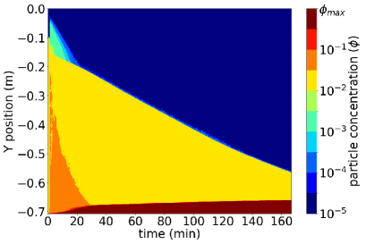
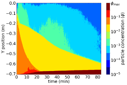
A more recent development related to settling elements is the use of heat (very abundant, as solar energy, in many concentrator plants in desert locations) to enhance settling (Reyes et al., 2019b). Heat injection affects the structure of the clear fluid boundary layer via natural convection in the downward-facing portion of settling elements. This sole mechanism, in the absence of particles, induces natural convection (Fujii and Imura, 1972; Soong et al., 1996). This process overlaps in a complex fashion with the particle-induced convection inherent to the Boycott effect. Figure 8 shows a spatiotemporal diagram of two-dimensional two-phase model simulations of a batch experiment solved using the same finite volume scheme used in Reyes and Ihle (2018), where it is first noted that the sediment layer took roughly half of the time to form in the heated case, corresponding to an imposed temperature of above the initial temperature of the suspension at the upper wall over the suspension temperature (Figure 8b), than in the isothermal one. Here, the boundary between the clarified layer and the suspension (a traveling iso-concentration wave), denoted using false color by the yellow-blue and yellow-green interface in the absence and presence of heating, respectively, is significantly steeper when the upper wall is heated, as noted from the scale of the abscissa in both graphs.
Despite the encouraging results referred above, it is noted that the heated case is also related to some degree of particle contamination in the clarified layer (light-blue and green on top of yellow false-color compared in Figure 8b). Temperature is a critical aspect that may induce, if it is inhomogeneous within the settler, flow short circuit through the formation of gravity currents (Brown, 1986). Even if the temperature feed is homogeneous, increasing it for a particular suspension may result on increased (and uncontrolled) feed flow that may cause a drop in the TRE (Takata and Kurose, 2017). It is therefore necessary to seek either for homogeneous temperature conditions inside the settler and to have proper knowledge of daily/seasonal variations of water temperature, so the performance can be adjusted accordingly or, if it cannot be controlled, be known beforehand. Therefore, this approach, which is presently under development, requires very tight control both of feed conditions and heating.
| (a) | (b) |
 |
 |
6 Final remarks
Water footprint minimization in mineral processing plants is among the top priorities of the mining industry. With that comes the need to fulfill the process objectives of extractive metallurgy. The present document has presented the use of SIS technology as a means to make better control of water recovery from thickeners by adding an independent unit process to control the quality of the overflow water (in the sense of suspended solid content). Figure 2 shows a lamella clarifier fitted with a feed tank where turbulence can be imposed and controlled. This gives an additional opportunity to design thickener overflow clarification strategies relying on reduced use of reagents, provided a thickener operation prioritizing settling velocity may be done at with lower flocculant consumption but at the expense of tighter control of dilution at the thickener. The details of such a tandem strategy are beyond the scope of the present paper, and certainly, a process engineering approach is required to explore the best simultaneous operational points. From this perspective, this problem resembles that of geometallurgy (reviewed by Lishchuk et al., 2020), as it is inherently bonded to mineral and water characteristics.
The present paper shows a convergence of the parallel alleys that have marked the research in the last century which started with the discovery of Boycott (1920), and the developments in the last 50 years concerning SIS equipment, mostly applied to wastewater. The PNK theory (based on mass balance concepts) matches the two-dimensional approach to set the minimum (infinitely wide) inclined plate length to host all particles of a specified size in a dilute suspension. This is to be tested in different cross-sectional geometries. This would help, in particular, to provide experimental support to what is suggested by Ihle and Reyes (2022) on the relevance of the cross-sectional shape on the footprint of SIS equipment. It would therefore be interesting to combine both approaches to update already existing engineering models for system design.
Although the development of SIS technology is mature, and that there are a number of well established industrial producers of this kind of equipment, there is room for improvement of the overall clarification process, especially in light of increasing and variable fine and ultrafine contents in mineral concentrator plants. The interplay between the use of additives, the kind and size of particles to be separated, the concentration of particles and the dimensional characteristics of the settlers imply a diversity of TRE results. From the perspective of equipment design, several improvement opportunities are yet to be explored in modern systems, including fine-tuning of settling element arrays (angle, spacing, and the potential inclusion of mechanical attachments for controlled vibration), to optimize inlet conditions to make the most of the settling element array and to optimize the design of settling elements. At this point, there is also an opportunity to use solar energy, which is particularly abundant in several mining operations of Chile, Australia, and elsewhere, to further reduce the footprint. Nonetheless, in this case, to alter design means to re-visit the physics behind the Boycott effect, which represents a challenge on fluid dynamics and the physics of suspensions. It is also noted that, despite the present update of the settling technology equipment, general observations, including the interlink between suspension characteristics and optimal settler design, still hold and justify the existence of SIS settler design from a research and development perspective.
Although the use of experimental techniques for system modeling is irreplaceable, the opportunities from existing modern computational capacity result in significantly reduced system development times. So far, this has particularly benefited the design of settling basins with attached arrays on inclined settling elements using low-computational-cost turbulence closures such as - and -, which are included in most commercial CFD packages. Comparatively, little work has been done concerning the use of high-resolution simulations to analyze the details of the flow, where such turbulence closures are less useful. This can be particularly challenging, given the potential width of the clear fluid boundary layer (in the case of subcritical settlers) configuring laminar flow, the potential particle size. It can have broad variations in the same sample and potentially multiple flow regimes: commonly turbulent flow near the inlet of the settler, transitional flow near the entry of the settling elements, and laminar flow within them. The opportunities that offer carefully chosen and configured Eulerian-Eulerian schemes (i.e., both solid and liquid phases seen as continuous) or Eulerian-Lagrangian setups allow not just to anticipate hydrodynamic instabilities that may cause detriment on performance (and to have a detailed knowledge of the system SOR under the strongly variable plant feed and reagent conditions described above) but also to reasonably model the downstream sludge flow.
Acknowledgements
The authors gratefully acknowledge support from the Department of Mining Engineering of University of Chile and the Chilean National Agency for Research and Development through PIA Grant AFB180004, Fondecyt Project 1211044, and National Doctoral Scholarship 21190656. CI also acknowledges support from the Vice-rectory of Research and Development Univ. Chile, Project code ENL11/20. CA acknowledges support of Nordita and the Swedish Research Council Grant No. 2018-04290; Nordita is partially supported by Nordforsk.
Appendix A Scale of clear fluid layer in subcritical mode of operation (negligible inertia)
Consider the scales , , , and . Here, and are velocity scales parallel and perpendicular to the upper wall (facing downwards) at a (small) distance from the upper wall. The latter distance is assumed much thinner than the longitudinal length scale so, to first order, , as confirmed by numerous experiments (Hill et al., 1977, and references therein). Continuity near the boundary layer implies that If the tube is tilted from the vertical, then , where is the projected height of the inclined tube.
Assuming that the flow at the boundary layer is laminar, then the force density balances the viscous force per unit volume, and therefore
| (23) |
Further, assuming that is on the order of the settling velocity, , implies that the longitudinal velocity and the thickness of the boundary layer verify (see also Blanchette, 2003):
| (24a) | ||||
| (24b) | ||||
Using , the dimensionless parameter corresponds to (22). Also, under this definition of , . From this boundary layer perspective, noting that , where is a longitudinal coordinate parallel to the upper wall), then, from (24b), .
List of symbols
| distance between control volume and inner diameter of lower portion of settler | |
| volume fraction (dimensionless) | |
| feed volume fraction (dimensionless) | |
| underflow volume fraction (dimensionless) | |
| Grashof-Reynolds number ratio (dimensionless) | |
| fluid phase dynamic viscosity (mass length-1 time-1) | |
| settling cell efficiency (dimensionless) | |
| inclination angle, measured from the horizontal | |
| boundary of the control volume (length2) | |
| control volume (length3) | |
| (dimensionless) | |
| fluid phase density (mass/length3) | |
| solid mass per unit volume (mass/length3) | |
| solid phase density (mass/length3) | |
| projected area of settler (length2) | |
| height of settling element, measured from the base (length) | |
| inside diameter of pipe (length) | |
| hexagon side in Figure 6 (length) | |
| particle diameter (length) | |
| drag force on a sediment particle (mass length/time2) | |
| force density by the sediment on the fluid (mass length-2 time-2) | |
| Grashof number (dimensionless) | |
| acceleration of gravity vector (length/time2) | |
| magnitude of acceleration of gravity vector (length/time2) | |
| height of suspension (length) | |
| unit normal pointing outward the control volume (dimensionless) | |
| longitudinal length scale (length) | |
| settling element (conduit) length (length) | |
| number of sediment particles per unit volume (length-3) | |
| SOR | surface overflow rate (length/time) |
| maximum volume flow per unit width to avoid particles at the overflow (length2/time) | |
| volume flow per unit width predicted by PNK theory (length2/time) | |
| Reynolds number (dimensionless) | |
| stability control parameter (dimensionless) | |
| critical stability parameter (dimensionless) | |
| clarification rate per unit depth (length2/time) | |
| clarification rate per unit area (length/time) | |
| dimensionless clarification parameter | |
| turbidity at the feed (turbidity units) | |
| turbidity at the overflow (turbidity units) | |
| TRE | turbidity removal efficiency (dimensionless) |
| time (time) | |
| mean flow velocity magnitude (length/time) | |
| solid phase velocity vector (length/time) | |
| velocity at the plane of symmetry | |
| velocity scale parallel to the slope (length/time) | |
| velocity scale normal to the slope (length/time) | |
| particle volume (length3) | |
| settling velocity vector (length/time) | |
| settling velocity vector magnitude (length/time) | |
| domain width (length) | |
| Stokes settling velocity (length/time) | |
| horizontal coordinate (Figure 4) or longitudinal coordinate (length) | |
| coordinate normal to settling element main axis (length) | |
| vertical coordinate |
References
- Acrivos and Herbolzheimer (1979) Acrivos, A., Herbolzheimer, E., 1979. Enhanced sedimentation in settling tanks with inclined walls. Journal of Fluid Mechanics 92, 435.
- Addai-Mensah et al. (2007) Addai-Mensah, J., Yeap, K.Y., McFarlane, A.J., 2007. The influential role of pulp chemistry, flocculant structure type and shear rate on dewaterability of kaolinite and smectite clay dispersions under couette Taylor flow conditions. Powder Technology 179, 79–83.
- Adelman et al. (2013) Adelman, M.J., Hurst, M.W., Weber-Shirk, M.L., Cabrito, T.S., Somogyi, C., Lion, L.W., 2013. Floc roll-up and its implications for the spacing of inclined settling devices. Environmental Engineering Science 30, 302–310.
- Al-Hashemi and Al-Amoudi (2018) Al-Hashemi, H.M.B., Al-Amoudi, O.S.B., 2018. A review on the angle of repose of granular materials. Powder Technology 330, 397–417.
- Arjmand et al. (2019) Arjmand, R., Massinaei, M., Behnamfard, A., 2019. Improving flocculation and dewatering performance of iron tailings thickeners. Journal of Water Process Engineering 31, 100873.
- Arratia et al. (2013) Arratia, C., Caulfield, C.P., Chomaz, J.M., 2013. Transient perturbation growth in time-dependent mixing layers. Journal of Fluid Mechanics 717, 90–133. doi:10.1017/jfm.2012.562.
- Bandrowski et al. (1997) Bandrowski, J., Hehlmann, J., Merta, H., Zioło, J., 1997. Studies of sedimentation in settlers with packing. Chemical Engineering and Processing: Process Intensification 36, 219–229.
- Baruth (2004) Baruth, E.E., 2004. Water treatment plant design. McGraw-Hill.
- Benjamin (1957) Benjamin, T.B., 1957. Wave formation in laminar flow down an inclined plane. Journal of Fluid Mechanics 2, 554–573.
- Bertrand-Krajewski (2004) Bertrand-Krajewski, J.L., 2004. TSS concentration in sewers estimated from turbidity measurements by means of linear regression accounting for uncertainties in both variables. Water Science and Technology 50, 81–88.
- Bhorkar et al. (2005) Bhorkar, M.P., Bhole, A.G., Nagarnaik, P.B., 2005. Application of Modified Tube Settler to Improve Sedimentation Process. Journal of Environmental Engineering .
- Bhorkar and Nagarnaik (2021) Bhorkar, M.P., Nagarnaik, P.B., 2021. Improvement in Sedimentation by Installation of Conventional and Modified Tube Settlers A Review. Journal of Indian Water Works Association , 69–74.
- Blanchette (2003) Blanchette, F., 2003. Sedimentation in a stratified ambient. Ph.D. thesis. MIT.
- Borhan (1989) Borhan, A., 1989. An experimental study of the effect of suspension concentration on the stability and efficiency of inclined settlers. Physics of Fluids A: Fluid Dynamics 1, 108–123.
- Borhan and Acrivos (1988) Borhan, A., Acrivos, A., 1988. The sedimentation of nondilute suspensions in inclined settlers. Physics of Fluids 31, 3488–3501.
- Boycott (1920) Boycott, A.E., 1920. Sedimentation of blood corpuscles. Nature 104, 532.
- Boyer et al. (2011) Boyer, F., Guazzelli, É., Pouliquen, O., 2011. Unifying suspension and granular rheology. Physical Review Letters 107, 188301.
- Brown (1986) Brown, D.J., 1986. Design of lamella separators. Part 2. Ph.D. thesis. Loughborough University of Technology.
- Bulatovic et al. (1999) Bulatovic, S., Wyslouzil, D.M., Kant, C., 1999. Effect of clay slimes on copper, molybdenum flotation from porphyry ores, in: Proceedings of Copper.
- Cassar et al. (2005) Cassar, C., Nicolas, M., Pouliquen, O., 2005. Submarine granular flows down inclined planes. Physics of Fluids 17, 103301. doi:10.1063/1.2069864.
- Castillo et al. (2019) Castillo, C., Ihle, C.F., Jeldres, R.I., 2019. Chemometric optimisation of a copper sulphide tailings flocculation process in the presence of clays. Minerals 9, 582.
- Chang et al. (2019) Chang, Y.C., Chiu, T.Y., Hung, C.Y., Chou, Y.J., 2019. Three-dimensional Eulerian-Lagrangian simulation of particle settling in inclined water columns. Powder Technology 348, 80–92.
- Chomaz (2005) Chomaz, J.M., 2005. Global instabilities in spatially developing flows: non-normality and nonlinearity. Annu. Rev. Fluid Mech. 37, 357–392.
- Clark et al. (2009) Clark, S.E., Elligson, J.C., Mikula, J.B., Roenning, C.D., Siu, C.Y.S., Hafera, J.M., 2009. Inclined plate settlers to treat stormwater solids. Journal of Environmental Engineering 137, 621–626.
- Concha (2014) Concha, F., 2014. Solid-liquid separation in the mining industry. Springer.
- Connelly (2011) Connelly, D., 2011. High clay ores a mineral processing nightmare. Australian Journal of Mining 24, 28–29.
- Contreras et al. (2020) Contreras, S., Castillo, C., Olivera-Nappa, Á., Townley, B., Ihle, C.F., 2020. A new statistically-based methodology for variability assessment of rheological parameters in mineral processing. Minerals Engineering 156, 106494.
- Crittenden et al. (2012) Crittenden, J.C., Trussell, R.R., Hand, D.W., Howe, K.J., Tchobanoglous, G., 2012. MWH’s water treatment: principles and design. John Wiley & Sons.
- Culp et al. (1968) Culp, G., Hansen, S., Richardson, G., 1968. High-Rate Sedimentation in Water Treatment Works. Journal-American Water Works Association 60, 681–698.
- Currie (2012) Currie, I.G., 2012. Fundamental mechanics of fluids. CRC Press.
- Dao et al. (2019) Dao, N.T.M., Terashima, M., Yasui, H., Others, 2019. Improvement of Suspended Solids Removal Efficiency in Sedimentation Tanks by Increasing Settling Area Using Computational Fluid Dynamics. Journal of Water and Environment Technology 17, 420–431.
- Das and Sarkar (2018) Das, A., Sarkar, B., 2018. Advanced gravity concentration of fine particles: A review. Mineral Processing and Extractive Metallurgy Review 39, 359–394.
- Davis (2010) Davis, M.L., 2010. Water and wastewater engineering: design principles and practice. McGraw-Hill Education.
- Davis and Acrivos (1985) Davis, R.H., Acrivos, A., 1985. Sedimentation of noncolloidal particles at low Reynolds numbers. Annual Review of Fluid Mechanics 17, 91–118.
- Davis et al. (1983) Davis, R.H., Herbolzheimer, E., Acrivos, A., 1983. Wave formation and growth during sedimentation in narrow tilted channels. Physics of Fluids 26, 2055–2064.
- De (2017) De, A., 2017. Sedimentation process and design of settling systems. Springer.
- Demir (1995) Demir, A., 1995. Determination of settling efficiency and optimum plate angle for plated settling tanks. Water Research 29, 611–616.
- Driscoll et al. (2008) Driscoll, T.P., Barber, J.B., Constable, S., Darnell, C., DiMenna, R., Gaines, B., Goodman, A., Hlavek, R., Johns, F.J., Jones, T.S., Kemp, G., Kim, B., Krill, W.P., Krishnanand, M., Millano, E.F., Nichols, C., Parham, G., Philbrook, D., Severin, B.F., Shamas, J., Shamskhorzani, R., Solvie, J., Venkatasubbiah, V., Wirtz, R., Wong-Chong, G., Yeh, B., Young, J., 2008. Industrial Wastewater Management, Treatment, and Disposal. Manual of Practive FD-3.
- Droste and Gehr (2019) Droste, R.L., Gehr, R.L., 2019. Theory and practice of water and wastewater treatment. 2 ed., John Wiley & Sons.
- Edzwald (2010) Edzwald, J.K., 2010. Water Quality and Treatment A Handbook on Drinking Water. McGrawHill.
- Fadel and Baumann (1990) Fadel, A.A., Baumann, E.R., 1990. Tube settler modeling. Journal of Environmental Engineering 116, 107–124.
- Fawell et al. (2019) Fawell, P.D., Nguyen, T.V., Solnordal, C.B., Stephens, D.W., 2019. Enhancing gravity thickener feedwell design and operation for optimal flocculation through the application of computational fluid dynamics. Mineral Processing and Extractive Metallurgy Review , 1–15.
- Feldthusen (2014) Feldthusen, M., 2014. Lamella settler. URL: https://patents.google.com/patent/RU2671734C2/en. rU2671734C2.
- Fischerström (1955) Fischerström, C.N., 1955. Sedimentation in rectangular basin, in: Proceedings of the American Society of Civil Engineers, ASCE. p. 687.
- Forsell and Hedström (1975) Forsell, B., Hedström, B., 1975. Lamella sedimentation: a compact separation technique. Journal (Water Pollution Control Federation) , 834–842.
- Franks et al. (2021) Franks, D.M., Stringer, M., Torres-Cruz, L.A., Baker, E., Valenta, R., Thygesen, K., Matthews, A., Howchin, J., Barrie, S., 2021. Tailings facility disclosures reveal stability risks. Scientific reports 11, 1–7.
- Fuchs et al. (2014) Fuchs, S., Mayer, I., Haller, B., Roth, H., 2014. Lamella settlers for storm water treatment–performance and design recommendations. Water Science and Technology 69, 278–285.
- Fuerstenau and Han (2003) Fuerstenau, M.C., Han, K.N., 2003. Principles of mineral processing. SME.
- Fujii and Imura (1972) Fujii, T., Imura, H., 1972. Natural-convection heat transfer from a plate with arbitrary inclination. International Journal of Heat and Mass Transfer 15, 755–767.
- Fujisaki (2010) Fujisaki, K., 2010. Enhancement of settling tank capacity using a new type of tube settler. Water Science and Technology 62, 1213–1220.
- Galvin (2021) Galvin, K.P., 2021. Process intensification in the separation of fine minerals. Chemical Engineering Science 231, 116293.
- Gräfe et al. (2017) Gräfe, M., Klauber, C., McFarlane, A.J., Robinson, D.J., 2017. Clays in the Minerals Processing Value Chain. Cambridge University Press.
- Graham and Lama (1963) Graham, W., Lama, R., 1963. Sedimentation in inclined vessels. The Canadian Journal of Chemical Engineering 41, 31–32.
- Guazzelli et al. (2012) Guazzelli, E., Morris, J.F., Guazzelli, É., Morris, J.F., 2012. A Physical Introduction to Suspension Dynamics. volume 45. Cambridge University Press.
- Hansen and Culp (1967) Hansen, S.P., Culp, G.I., 1967. Applying shallow depth sedimentation theory. Journal-American Water Works Association 59, 1134–1148.
- Hartman et al. (1994) Hartman, M., Trnka, O., Svoboda, K., 1994. Free settling of nonspherical particles. Industrial & Engineering Chemistry Research 33, 1979–1983.
- He and Marsalek (2009) He, C., Marsalek, J., 2009. Vortex plate for enhancing particle settling. Journal of Environmental Engineering 135, 627–635.
- He et al. (2008) He, C., Wood, J., Marsalek, J., Rochfort, Q., 2008. Using CFD modeling to improve the inlet hydraulics and performance of a storm-water clarifier. Journal of Environmental Engineering 134, 722–730.
- Hendricks (2006) Hendricks, D.W., 2006. Water Treatment Unit Processes: Physical and Chemical. CRC Press.
- Herbolzheimer (1983) Herbolzheimer, E., 1983. Stability of the flow during sedimentation in inclined channels. Physics of Fluids 26, 2043–2054.
- Herbolzheimer and Acrivos (1981) Herbolzheimer, E., Acrivos, A., 1981. Enhanced sedimentation in narrow tilted channels. Journal of Fluid Mechanics 108, 485.
- Hill et al. (1977) Hill, W.D., Rothfus, R.R., Li, K., 1977. Boundary-enhanced sedimentation due to settling convection. International Journal of Multiphase Flow 3, 561–583.
- Hincapié and Marchese (2015) Hincapié, E., Marchese, A.J., 2015. An ultrasonically enhanced inclined settler for microalgae harvesting. Biotechnology Progress 31, 414–423.
- Huang et al. (2008) Huang, T.L., Li, Y.X., Zhang, H., 2008. Theoretical analysis on non-uniformity of water distribution and influence of construction parameters on settling efficiency. Water Science and Technology 58, 1007–1014.
- Ihle (2014) Ihle, C.F., 2014. The need to extend the study of greenhouse impacts of mining and mineral processing to hydraulic streams: Long distance pipelines count. Journal of Cleaner Production 84, 597.
- Ihle and Kracht (2018) Ihle, C.F., Kracht, W., 2018. The relevance of water recirculation in large scale mineral processing plants with a remote water supply. Journal of Cleaner Production 177, 34–51.
- Ihle and Reyes (2022) Ihle, C.F., Reyes, C., 2022. A new criterion to estimate the capacity of steeply inclined settlers of arbitrary cross-sectional shape. Powder Technology. 397, 117004.
- Ji et al. (2013) Ji, Y., Lu, Q., Liu, Q., Zeng, H., 2013. Effect of solution salinity on settling of mineral tailings by polymer flocculants. Colloids and Surfaces A: Physicochemical and Engineering Aspects .
- Jiménez and Ramos (1997) Jiménez, B., Ramos, J., 1997. High-Rate Sedimentation for Wastewater Treatment Processes. Environmental Technology 18, 1099–1110.
- Kapoor and Acrivos (1995) Kapoor, B., Acrivos, A., 1995. Sedimentation and sediment flow in settling tanks with inclined walls. Journal of Fluid Mechanics 290, 39.
- Kerswell (2018) Kerswell, R., 2018. Nonlinear nonmodal stability theory. Annual Review of Fluid Mechanics 50, 319–345.
- Kim (2013) Kim, J., 2013. Inclined plates apparatus and inclinded settling tank. URL: https://patents.google.com/patent/KR101348433B1/en. kR101348433B1.
- Kinosita (1949) Kinosita, K., 1949. Sedimentation in tilted vessels. Journal of Colloid Science 4, 525–536.
- Komar and Reimers (1978) Komar, P.D., Reimers, C.E., 1978. Grain shape effects on settling rates. Journal of Geology 86, 193–209.
- Kompala (2017) Kompala, D.S., 2017. Particle settling devices. URL: https://patents.google.com/patent/US10596492B2/en. uS10596492B2.
- Kowalski (2004) Kowalski, W.P., 2004. The method of calculations of the sedimentation efficiency in tanks with lamella packets. Archives of Hydro-Engineering and Environmental Mechanics 51, 371–385.
- Laux and Ytrehus (1997) Laux, H., Ytrehus, T., 1997. Computer simulation and experiments on two-phase flow in an inclined sedimentation vessel. Powder Technology 94, 35–49.
- Lee (2015) Lee, B., 2015. Experimental study to evaluate design procedure and proposed improvement measures for clarifier with inclined plates. Environmental Engineering Research 20, 298–305.
- Letterman et al. (1999) Letterman, R.D., Amirtharajah, A., O’Melia, C.R., 1999. Water quality and treatment. A handbook of community water supplies. AWWA, Mc Graw-Hill, New York .
- Leung (1983) Leung, W.F., 1983. Lamella and tube settlers. 2. Flow stability. Industrial & Engineering Chemistry Process Design and Development 22, 68–73.
- Leung and Probstein (1983) Leung, W.F., Probstein, R.F., 1983. Lamella and tube settlers. 1. Model and operation. Industrial & Engineering Chemistry Process Design and Development 22, 58–67.
- Lin (2014) Lin, S.D., 2014. Water and wastewater calculations manual. McGraw-Hill Education.
- Lishchuk et al. (2020) Lishchuk, V., Koch, P.H., Ghorbani, Y., Butcher, A.R., 2020. Towards integrated geometallurgical approach: Critical review of current practices and future trends. Minerals Engineering 145, 106072.
- López-Espejo and Ihle (2022) López-Espejo, C., Ihle, C.F., 2022. Technical Assessment of Secondary Sedimentation Process in Copper Sulphide Tailings with the Presence of Clays, in Continental and Sea Water. Minerals 12, 257.
- Lottermoser (2010) Lottermoser, B., 2010. Mine wastes: characterization, treatment and environmental impacts. Springer Science & Business Media.
- Merrill et al. (2017) Merrill, J., Voisin, L., Montenegro, V., Ihle, C.F., McFarlane, A., 2017. Slurry rheology prediction based on hyperspectral characterization models for minerals quantification. Minerals Engineering 109, 126–134.
- Metso (2021) Metso, 2021. Inclined plate settlers - Metso Outotec. URL: https://www.mogroup.com/portfolio/ips-series.
- Meyer and Linden (2014) Meyer, C.R., Linden, P.F., 2014. Stratified shear flow: experiments in an inclined duct. Journal of Fluid Mechanics 753, 242–253.
- Morin (2009) Morin, A., 2009. Installation for decanting stormwater with a hydraulic distributor. European Patent EP1391228A1. URL: https://worldwide.espacenet.com/patent/search/family/030471068/publication/EP1391228A1?q=pn%3DEP1391228.
- Nakamura and Kuroda (1937) Nakamura, H., Kuroda, K., 1937. La cause de l’acceleration de la vitesse de sedimentation des suspensions dans les recipients inclines. Keijo J. Med. 8, 256–296.
- Nguyen et al. (2019) Nguyen, T., Dao, N.T., Liu, B., Terashima, M., Yasui, H., 2019. Computational Fluid Dynamics Study on Attainable Flow Rate in a Lamella Settler by Increasing Inclined Plates. Journal of Water and Environment Technology 17, 76–88.
- Nguyentranlam and Galvin (2004) Nguyentranlam, G., Galvin, K.P., 2004. Applications of the Reflux Classifier in solid–liquid operations. International Journal of Mineral Processing 73, 83–89.
- Nordic Water (2021) Nordic Water, 2021. Lamella Separator LS — Nordic Water. URL: https://www.nordicwater.com/product/lamella-separator-ls.
- Northey et al. (2014) Northey, S., Mohr, S., Mudd, G.M., Weng, Z., Giurco, D., 2014. Modelling future copper ore grade decline based on a detailed assessment of copper resources and mining. Resources, Conservation and Recycling 83, 190–201.
- Okoth et al. (2008) Okoth, G., Centikaya, S., Brüggemann, J., Thöming, J., 2008. On hydrodynamic optimisation of multi-channel counter-flow lamella settlers and separation efficiency of cohesive particles. Chemical Engineering and Processing: Process Intensification 47, 90–100.
- Oliver and Jenson (1964) Oliver, D.R., Jenson, V.G., 1964. The inclined settling of dispersed suspensions of spherical particles in square-section tubes. Canadian Journal of Chemical Engineering 42, 191–195.
- Palma et al. (2018) Palma, S., Ihle, C.F., Tamburrino, A., 2018. Characterization of a sediment layer of concentrated fluid-solid mixtures in tilted ducts at low Reynolds numbers. Powder Technology 325, 192–201.
- Palma et al. (2016) Palma, S., Ihle, C.F., Tamburrino, A., Dalziel, S.B., 2016. Particle organization after viscous sedimentation in tilted containers. Physics of Fluids 28, 073304.
- Parkson (2021) Parkson, 2021. Lamella EcoFlow - Parkson Corporation. URL: https://www.parkson.com/products/lamella-ecoflow.
- Patankar and Joseph (2001) Patankar, N.A., Joseph, D.D., 2001. Modeling and numerical simulation of particulate flows by the Eulerian–Lagrangian approach. International Journal of Multiphase Flow 27, 1659–1684.
- Ponder (1925) Ponder, E., 1925. On sedimentation and rouleaux formation-I. Quarterly Journal of Experimental Physiology: Translation and Integration 15, 235–252.
- Probstein et al. (1977) Probstein, R.F., Yung, D., Hicks, R.E., 1977. A model for lamella settlers, in: Theory, Practice, and Process Principles for Physical Separations’, Engng Foundation Conf., Asilomar, California.
- Qinglun et al. (2012) Qinglun, S., Xianzhong, R., Shilei, G., Kaijun, C., Chunfeng, L., 2012. Ultrasonic solid-liquid separation skid. URL: https://patents.google.com/patent/CN202594928U/en. cN202594928U.
- Rao and Finch (1989) Rao, S.R., Finch, J.A., 1989. A review of water re-use in flotation. Minerals Engineering 2, 65–85.
- Reyes et al. (2019a) Reyes, C., Álvarez, M., Ihle, C.F., Contreras, M., Kracht, W., 2019a. The influence of seawater on magnetite tailing rheology. Minerals Engineering 131, 363–369.
- Reyes and Ihle (2018) Reyes, C., Ihle, C.F., 2018. Numerical simulation of cation exchange in fine-coarse seawater slurry pipeline flow. Minerals Engineering 117, 14–23.
- Reyes et al. (2019b) Reyes, C., Ihle, C.F., Apaz, F., Cisternas, L.A., 2019b. Heat-Assisted Batch Settling of Mineral Suspensions in Inclined Containers. Minerals 9, 228.
- Rubinstein (1980) Rubinstein, I., 1980. A steady laminar flow of a suspension in a channel. International Journal of Multiphase Flow 6, 473–490.
- Saady (2012) Saady, N.M.C., 2012. Utilizing settling tests to design a conventional upflow settling tank modified with inclined plates. Water Science and Technology 66, 858–864.
- Salem et al. (2011) Salem, A.I., Okoth, G., Thöming, J., 2011. An approach to improve the separation of solid–liquid suspensions in inclined plate settlers: CFD simulation and experimental validation. Water Research 45, 3541–3549.
- Sarmiento and Uhlherr (1978) Sarmiento, G., Uhlherr, P.H.T., 1978. Batch sedimentation of red mud suspensions in an inclined tube. Canadian Journal of Chemical Engineering 56, 705–710.
- Schmid (2007) Schmid, P.J., 2007. Nonmodal stability theory. Annu. Rev. Fluid Mech. 39, 129–162.
- Schneider (1982) Schneider, W., 1982. Kinematic-wave theory of sedimentation beneath inclined walls. Journal of Fluid Mechanics 120, 323–346.
- Searles et al. (1994) Searles, J., Todd, P., Kompala, D., 1994. Viable cell recycle with an inclined settler in the perfusion culture of suspended recombinant Chinese hamster ovary cells. Biotechnology Progress 10, 198–206.
- Seyssiecq et al. (2003) Seyssiecq, I., Ferrasse, J.H., Roche, N., 2003. State-of-the-art: rheological characterisation of wastewater treatment sludge. Biochemical Engineering Journal 16, 41–56.
- Shaqfeh and Acrivos (1986) Shaqfeh, E.S.G., Acrivos, A., 1986. The effects of inertia on the buoyancy-driven convection flow in settling vessels having inclined walls. Physics of Fluids 29, 3935–3948.
- Shaqfeh and Acrivos (1987) Shaqfeh, E.S.G., Acrivos, A., 1987. Enhanced sedimentation in vessels with inclined walls: experimental observations. Physics of Fluids 30, 1905–1914.
- Smith and Davis (2013) Smith, B.T., Davis, R.H., 2013. Particle concentration using inclined sedimentation via sludge accumulation and removal for algae harvesting. Chemical Engineering Science 91, 79–85.
- Snider et al. (1998) Snider, D.M., O’Rourke, P.J., Andrews, M.J., 1998. Sediment flow in inclined vessels calculated using a multiphase particle-in-cell model for dense particle flows. International Journal of Multiphase Flow 24, 1359–1382.
- Soong et al. (1996) Soong, C.Y., Tzeng, P.Y., Chiang, D.C., Sheu, T.S., 1996. Numerical study on mode-transition of natural convection in differentially heated inclined enclosures. International Journal of Heat and Mass Transfer .
- Stokes (1851) Stokes, G.G., 1851. On the effect of internal friction of fluids on the motion of pendulums. Trans. Camb. Phil. Soc 9, 8–106.
- Takata and Kurose (2017) Takata, K., Kurose, R., 2017. Influence of density flow on treated water turbidity in a sedimentation basin with inclined plate settler. Water Science and Technology: Water Supply 17, 1140–1148.
- Tarleton and Wakeman (2007) Tarleton, S., Wakeman, R., 2007. Solid/liquid separation: equipment selection and process design. Elsevier.
- Tarpagkou and Pantokratoras (2014) Tarpagkou, R., Pantokratoras, A., 2014. The influence of lamellar settler in sedimentation tanks for potable water treatment - A computational fluid dynamic study. Powder Technology 268, 139–149.
- Tripathy et al. (2015) Tripathy, S.K., Bhoja, S.K., Kumar, C.R., Suresh, N., 2015. A short review on hydraulic classification and its development in mineral industry. Powder Technology 270, 205–220.
- Tungpalan et al. (2015) Tungpalan, K., Manlapig, E., Andrusiewicz, M., Keeney, L., Wightman, E., Edraki, M., 2015. An integrated approach of predicting metallurgical performance relating to variability in deposit characteristics. Minerals Engineering 71, 49–54.
- Vohra and Ghosh (1971) Vohra, D.K., Ghosh, B., 1971. Studies of sedimentation in inclined tubes. Ind. Engng Chem. 13, 32–40.
- Wang et al. (2014) Wang, C., Harbottle, D., Liu, Q., Xu, Z., 2014. Current state of fine mineral tailings treatment: A critical review on theory and practice. Minerals Engineering 58, 113–131.
- Wang et al. (2020) Wang, K., Li, Y., Ren, S., Yang, P., 2020. A case study on settling process in inclined-tube gravity sedimentation tank for drip irrigation with the yellow river water. Water 12, 1685.
- Wenk (1990) Wenk, S.E., 1990. The theory, design and experience of Lamella Gravity Settlers in the phosphate industry. Fertilizer Research 25, 139–143.
- Westech (2021) Westech, 2021. SuperSettler Inclined Plate Clarifier. URL: https://www.westech-inc.com/products/inclined-plate-clarifier-supersettler.
- Willis (1978) Willis, R.M., 1978. Tubular settlers - A technical review. Journal (American Water Works Association) , 331–335.
- Wilson (2005) Wilson, T.E., 2005. Clarifier Design: WEF Manual of Practice No. FD-8. Second ed., McGraw-Hill, Alexandria, USA.
- Wisniewski (2013) Wisniewski, E., 2013. Sedimentation tank design for rural communities in the hilly regions of Nepal. Journal of Humanitarian Engineering 2, 43–54.
- Xu (2016) Xu, Y., 2016. Uniform-liquid-collection inclined plate component. URL: https://patents.google.com/patent/CN105521625A/en. cN105521625A.
- Xu and Michaelides (2005) Xu, Z.J., Michaelides, E.E., 2005. A numerical simulation of the Boycott effect. Chem. Eng. Comm. 192, 532–549.
- Yao (1970) Yao, K.M., 1970. Theoretical study of high-rate sedimentation. Journal of the Water Pollution Control Federation , 218–228.
- Yih (1963) Yih, C.S., 1963. Stability of liquid flow down an inclined plane. Physics of Fluids 6, 321–334.
- Zahavi and Rubin (1975) Zahavi, E., Rubin, E., 1975. Settling of solid suspensions under and between inclined surfaces. Industrial & Engineering Chemistry Process Design and Development 14, 34–41.
- Zbik et al. (2008) Zbik, M.S., Smart, R.S.C., Morris, G.E., 2008. Kaolinite flocculation structure. Journal of Colloid and Interface Science 328, 73–80.
- Zhang and Davis (1990) Zhang, X., Davis, R.H., 1990. Particle classification using inclined settlers in series and with underflow recycle. Industrial & Engineering Chemistry Research 29, 1894–1900.
- Zhou (2013) Zhou, X., 2013. Vibrating inclined plate box settlement separator. URL: https://patents.google.com/patent/US9999847B2/en. uS9999847B2.
- Zhou et al. (2012) Zhou, X.L., Long, Z.Y., Hu, W.Y., Zhang, X.M., Shi, Z.X., Sun, D.Y., Zhang, W.B., 2012. Study on the vibration lamella thickener and its application in mineral processing plant, in: Applied Mechanics and Materials, Trans Tech Publ. pp. 333–341.
- Zhou et al. (2001) Zhou, Z., Scales, P.J., Boger, D.V., 2001. Chemical and physical control of the rheology of concentrated metal oxide suspensions. Chemical Engineering Science 56, 2901–2920.
- Zioło (1996) Zioło, J., 1996. Influence of the system geometry on the sedimentation effectiveness of lamella settlers. Chemical Engineering Science 51, 149–153.