Enhanced-rate Iterative Beamformers for Active IRS-assisted Wireless Communications
Abstract
Compared to passive intelligent reflecting surface (IRS), active IRS is viewed as a more efficient promising technique to combat the double-fading impact in IRS-aided wireless network. In this paper, in order to boost the achievable rate of user in such a wireless network, three enhanced-rate iterative beamforming methods are proposed by designing the amplifying factors and the corresponding phases at active IRS. The first method, maximizing the simplified signal-to-noise ratio (Max-SSNR) is designed by omitting the cross-term in the definition of rate. Using the Rayleigh-Ritz (RR) theorem, Max-SSNR-RR is proposed to iteratively optimize the norm of beamforming vector and its associated normalized vector. In addition, generalized maximum ratio reflection (GMRR) is presented with a closed-form expression, which is motivated by the maximum ratio combining. To further improve rate, maximizing SNR (Max-SNR) is designed by fractional programming (FP), which is called Max-SNR-FP. Simulation results show that the proposed three methods make an obvious rate enhancement over Max-reflecting signal-to-noise ratio (Max-RSNR), maximum ratio reflection (MRR), selective ratio reflecting (SRR), equal gain reflection (EGR) and passive IRS, and are in increasing order of rate performance as follows: Max-SSNR-RR, GMRR, and Max-SNR-FP.
Index Terms:
Active intelligent reflecting surface, double-fading, achievable rate, wireless networks.I Introduction
Recently, due to its low circuit cost and power consumption, intelligent reflecting surface (IRS) is becoming an extremely hot research topic and a very promising technique for future wireless networks like B5G and 6G [1]. It has the following major advantages: extend coverage [2], improve rate [3], enhance security [4], strengthen covert communication [5], and increase spatial degrees of freedom (DOF) [6, 7]. To achieve the above goals, IRS can be diversely combined with directional modulation networks [6], multiple-input multiple-output [8], and relay networks [9]. A mobile IRS has been applied to undermine communications to remove the wireless blind zone and improve the wireless communication connectivity in such a situation.
In IRS-aided single-input single-output (SISO) system [2], the authors derived outage probability and channel ratio gain probability expressions and then used them to analyze the coverage of the IRS, which showed that IRS provides greater coverage, and improves signal-to-noise ratio gain. [4] studied the security of IRS-assisted multi-group multicast communication system, and proposed alternative optimization schemes based on semidefinite relaxation and second-order cone programming. The simulation results showed that the two proposed schemes can greatly improve the system performance. In IRS-assisted beamforming and broadcasting [10], the authors derived the free-space path loss, which was related to the IRS distance from the transmitter/receiver IRS, the size of the IRS, the near field/far field and the radiation pattern of the antenna and cell. To analyze the impact of discrete phase shifters on the performance of IRS-aided wireless network system, based on the law of large numbers and Rayleigh distribution, the performance loss analysis was presented under the line-of-sight channels and Rayleigh channels respectively [11].
In addition, IRS can be applied in various scenarios, such as: multi-user multiple-input single-output communication system [12], and multi-IRS-assisted cell-free network [13], respectively. In [12], the authors applied fractional programming (FP) and the non-convex block coordinate descent to obtain a smooth solution. In [13], FP was applied by transforming the non-convex function through a multidimensional complex quadratic transform, thus optimizing the beamforming vectors through an alternating optimization structure.
However, due to the double fading effect of the reflecting channel link between the transmitter and the user, passive IRS helps to achieve a limited gain in rate performance compared to the case without IRS. In order to compensate for the serious dual-path loss in the cascade channel, the passive IRS need to be equipped with thousands or ten thousands elements to achieve significant passive beamforming gain [14]. Moreover, for the traditional passive structure, IRS can only adjust the phase of the incident signal, which limits the gain brought by beamforming. As active IRS emerges, the double-fading effect can be broken completely due to the fact that it is capable of amplifying and reflecting the incident signal simultaneously. In the active IRS-assisted multi-user system [15], the reflection matrix of the IRS and the beamforming vector of the BS were jointly optimized with the objective of minimizing the transmission power of the BS. To deal with the nonconvex design problem, the authors proposed the bilinear transformation and inner approximation methods. In [16], the authors derived the optimal power distribution between the transmit signal power of the BS and the output signal power of the IRS, and the results showed that active IRS was superior if the power budget was not very small and the number of IRS components was not very large. In an active IRS-assisted single-cell wireless network [17], a hybrid Gamma distribution was applied to obtain the average signal-to-noise ratio at user fading. With a fixed budget and a small number of reflected cells, active IRS obtained higher throughput than passive IRS.
In [18], a comparison between passive and active IRSs was made to show that the latter may harvest a dramatic rate gain over the former in typical scenarios. In the single-user case, in [18], the authors proposed a equal-gain reflecting (EGR) beamformer with phase alignment with the corresponding product channel and equal amplifying factor. Obviously, this method has not fully explored the double-fading benefits of product channels. To address such a problem, in [19], three high-performance methods, maximum reflecting signal-to-noise ratio (Max-RSNR), maximum ratio reflecting (MRR) and selective ratio combining (SRR), were proposed. Their main advantages are low-complexity with closed-form or semi-closed-form solutions and realize some rate improvement over EGR in [18]. In active IRS aided single-input multiple-output scenario [20], successive convex approximation (SCA) was proposed to separately design the amplitude and phase of the active IRS via maximizing user’s achievable rate. But, their aim is to not maximize the total SNR at user in as [19]. For example, the best beamformer Max-RSNR in [19] is only to maximize the reflected SNR by omitting the direct-path signal. Thus, it is obvious that there is still a large performance room to improve the achievable rate in such an active IRS-aided system. Thus, in this paper, to harvest more rate gain achieved by active IRS, we propose three enhanced-rate iterative beamformers with slight increased complexities.
-
1.
To improve the achievable rate of methods in [18][19], maximizing simplified SNR (Max-SSNR) is formalized. Through omitting the cross-term, which will significantly simplify the solving process. Max-SSNR may be directly solved by the distinct way: Rayleigh-Ritz (RR) ratio, which are short for Max-SSNR-RR. Here, an iterative process is introduced between the norm of beamforming vector and its normalized vector. In additon, motivated by the concepts of maximum ratio combining and Max-RSNR, an iterative generalized maximum ratio reflection (GMRR) is proposed. Simulation results show that the two methods strike a good balance between rate performance and complexity.
-
2.
To further improve the achievable rate, under the power constraint of active IRS, the objective function is to maximize the SNR. Two-level iteration by fractional programming (FP), which is called Max-SNR-FP. Simulation results show that the Max-SNR-FP method achieves about 1-3 bits higher than methods in [19] in terms of achievable rate, and is slightly better than alternative optimization (AO) in [18] and SCA in [20] in terms of rate performance.
The remainder is organized as follows. Section II presents the system model and three methods are proposed in Section III. In Section IV, numerical simulations are presented, and Section V draws conclusions.
: In this paper, bold lowercase and uppercase letters represent vectors and matrices, respectively. Signs , , , , and denote the conjugate transpose operation, inverse operation, real part operation, modulus operation, conjugate operation and 2-norm operation, respectively. The notation is the identity matrix, the sign represents the expectation operation, and denotes the diagonal operator of converting vector into a diagonal matrix.
II system model

Fig. 1 depicts a diagram of an active IRS-assisted wireless network. Both base station (BS) and user are equipped with single antenna. IRS is equipped with active reflecting elements, and the amplification factor for element is denoted by . Without loss of generality, it is assumed that all three channels from the BS to the IRS, IRS to the user, and the BS to the user are Rayleigh fading.
The signal arriving at the IRS is given by
| (1) |
where stands for the channel from BS to IRS, and indicates that the transmit signal at BS satisfying .
The signal reflected by IRS can written as
| (2) |
where denotes the diagonal matrix of the active IRS, and represents the additive white Gaussian noise (AWGN) with distribution .
The total power reflected by IRS is given by
| (3) | ||||
where represents the reflecting power constraint of the IRS, and . Let us define a normalized form of the beamforming vector at IRS as
| (4) |
where = with being the th iteration in our iteration structure between the norm of and its normalized vector.
Therefore, (3) can be rewritten as
| (5) |
According to (5), can be given by
| (6) |
The signal received by the user can be expressed as
| (7) |
where , and denotes the channels from BS to user and IRS to user, and indicates the AWGN at the user receiver. According to (7), the total received power at user can be described as
| (8) |
From (8), the signal-to-noise ratio (SNR) of the user can be formulated
| (9) |
The achievable rate of the user can be written as
| (10) | ||||
III Proposed Three Methods
In what follows, to enhance the rate performance, three high-rate iterative methods, called Max-SSNR-RR, GMRR and Max-SNR-FP, are proposed for an active IRS-aided wireless network. Compared with passive IRS, MRR, SRR, EGR and Max-RSNR, the proposed three methods perform much better in terms of rate performance.
III-A Proposed Max-SSNR-RR
The total average receive SNR at user is written as
| (11) |
Due to the fact that the cross-term in numerator in (11) will lead to a difficulty of optimizing by maximizing SNR. For convenience of calculating below, we set the cross term to to form a simplified signal-to-noise ratio (SSNR) as
| (12) |
with replacing in (11) by . The optimization problem of maximizing SNR can be expressed as
| (13a) | ||||
| (13b) | ||||
Accordingly, given the value of and using the Rayleigh-Ritz ratio theorem, is the eigenvector corresponding to the largest eigenvalue of the matrix of the following
| (14) |
Plugging the solution to (14) in (6) gives the value of at iteration . Then, an alternate iteration between and are performed until the terminal condition is satisfied. The initial value of with is assigned to be the MRR in [19].
III-B Proposed GMMR
From (9), the reflecting SNR (RSNR) can be written as
| (15) |
Using the computed value of , the above RSNR expression can be converted into
| (16) |
Let us define
| (17) |
which is called the feature matrix of Max-RSNR. According to (17), (16) can be rewritten as
| (18) |
Let us define
| (19) |
Therefore, (18) can be rewritten as
| (20) |
Clearly, is a diagonal matrix. Therefore, the eigenvalue decomposition form of can be easily written as . is written as follows:
| (21) |
which directly gives the corresponding value of diagonal matrix
| (22) |
where .
Inspired by maximum ratio combining at receiver, the beamforming form is given by
| (23) |
Plugging the above expression in (19) yields
| (24) |
where represents the phase of the direction channel complex gain from BS to user.
III-C Proposed Max-SNR-FP
The SNR is rewritten as the following equation
| (25a) | ||||
| (25b) | ||||
where
| (26) | |||
| (27) |
Which is converted into
| (28a) | ||||
| s.t. | (28b) | |||
in terms of the Dinkelbach’s Transform in [21], where , , and is a new auxiliary variable. The above optimization problem is addressed by the following iterative updating process
| (29) |
where is the iteration index.
In (28), is a non-concave function, which can be linearized as the convex function
| (30) |
Placing the above linear approximation in (28) forms a convex optimization
| (31a) | ||||
| s.t. | (31b) | |||
which may be solved and implemented by using CVX to output the value of , where is taken to be in [19]. Based on (6), (29), and (30), a two-layer iterative structure is proposed as listed in the following table Algorithm I, named Max-SNR-FP.
IV Simulation Results and Discussions
In this section, numerical simulation results are conducted to evaluate the rate and convergent performance of our proposed methods. Simulation parameters are set as follows: = 20 dBm, = 35 dBm, and = -70 dBm. The BS, active IRS, and user are located at (0 m, 0 m), (80 m, 20 m), and (150 m, 0 m), respectively. The path loss at the distance is modeled as , where = -30dB represents the path loss reference distance = 1m, and is the path loss exponent. The path loss exponents from BS to IRS, IRS to user, and BS to user are 2.3, 2.3, and 3.9 respectively.
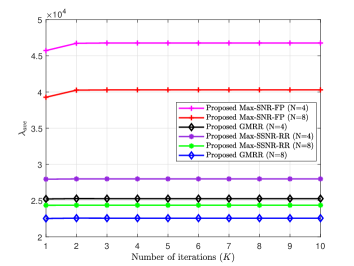
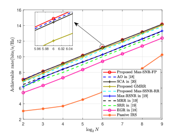
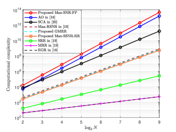
Fig. 2 depicts the convergent curves of the proposed three methods GMRR, Max-SNR-FP and Max-SSNR-RR with = 4 and 8. From the Fig. 2, it can be seen that all three methods proposed require about iterations to reach the convergence ceiling. Therefore, they have a fast convergent speed.
Fig. 3 demonstrates the achievable rate versus the number of IRS elements for the proposed three methods Max-SSNR-RR, GMRR, and Max-SNR-FP with all methods in [19], AO in [18], SCA in [20] and passive IRS as performance comparison benchmarks. The proposed three methods have made a significant rate enhancement over passive IRS. Particularly, the proposed Max-SNR-FP achieves about 4-bit rate gains over passive IRS when IRS is small-scale. Even, the proposed three methods still harvest more than 1-bit rate gains over three closed-form solutions MRR, SRR and EGR. The proposed Max-SNR-FP is slightly better than AO in [18] and SCA in [20] in terms of rate performance.
Fig. 4 illustrates the computational complexities of the proposed methods versus the number of IRS elements with existing methods in [18, 19, 20] as perfomance benchmarks. From this figure, it is seen that there is an increasing order in complexity (FLOPs): EGR ( FLOPs), MRR ( FLOPs), SRR ( FLOPs), the proposed GMMR, the proposed Max-SSNR-RR, Max-RSNR in [19] ( FLOPs), SCA in [20] ( FLOPs), AO in [18] ( FLOPs), and Max-SNR-FP ( FLOPs). In paritcular, the proposed iterative GMMR and Max-SSNR-RR achieve far lower-complexity than AO and SCA in [18, 20], and AO in [18] with a slight rate performance loss over the latter whereas the proposed Max-SNR-FP performs better than them using a higher complexity. Thus, we conclude the proposed GMMR and Max-SSNR-RR strike a good balance between rate performance and complexity.
V Conclusions
In this paper, three high-performance methods, Max-SSNR-RR, GMRR, and Max-SNR-FP, were presented to separately optimize the amplitude and phase of active IRS to make a rate enhancement for wireless network. They all adopt the same iterative architecture, which transforms the total beamforming problem at IRS into two subproblems: given its norm, its phase or normalized beamforming vector was optimized by different rules like Max-SNR or Max-RSNR, given its normalized vector, its norm was computed by power constraint. Simulation results indicated that the proposed three methods outperform MRR, SRR, EGR and the passive IRS case in accordance with rate. Their rates are in increasing order: Max-SSNR-RR, GMRR, and Max-SNR-FP. Additionally, Max-SNR-FP achieves a slightly higher achievable rate performance than AO in [18] and SCA in [20], and the proposed GMMR and Max-SSNR-RR have stricken a good balance between rate performance and complexity.
References
- [1] Q. Wu and R. Zhang, “Intelligent reflecting surface enhanced wireless network via joint active and passive beamforming,” IEEE Trans. Wirel. Commun., vol. 18, no. 11, pp. 5394–5409, Nov. 2019.
- [2] L. Yang, Y. Yang, M. O. Hasna, and M.-S. Alouini, “Coverage, probability of SNR gain, and DOR analysis of RIS-aided communication systems,” IEEE Wireless Commun. Lett., vol. 9, no. 8, pp. 1268–1272, Aug. 2020.
- [3] Q. Wu and R. Zhang, “Beamforming optimization for wireless network aided by intelligent reflecting surface with discrete phase shifts,” IEEE Trans. Commun., vol. 68, no. 3, pp. 1838–1851, May 2020.
- [4] W. Shi, J. Li, G. Xia, Y. Wang, X. Zhou, Y. Zhang, and F. Shu, “Secure multigroup multicast communication systems via intelligent reflecting surface,” China Communications, vol. 18, no. 3, pp. 39–51, 2021.
- [5] X. Zhou, S. Yan, Q. Wu, F. Shu, and D. W. K. Ng, “Intelligent reflecting surface (IRS)-aided covert wireless communications with delay constraint,” IEEE Trans. Wirel. Commun., vol. 21, no. 1, pp. 532–547, Jan. 2022.
- [6] F. Shu, Y. Teng, J. Li, M. Huang, W. Shi, J. Li, Y. Wu, and J. Wang, “Enhanced secrecy rate maximization for directional modulation networks via IRS,” IEEE Trans. Commun., vol. 69, no. 12, pp. 8388–8401, Dec. 2021.
- [7] H. Do, N. Lee, and A. Lozano, “Line-of-Sight MIMO via Intelligent Reflecting Surface,” IEEE Trans. Wirel. Commun., 2022.
- [8] C. Pan, H. Ren, K. Wang, W. Xu, M. Elkashlan, A. Nallanathan, and L. Hanzo, “Multicell MIMO communications relying on intelligent reflecting surfaces,” IEEE Trans. Wirel. Commun., vol. 19, no. 8, pp. 5218–5233, Aug. 2020.
- [9] X. Wang, F. Shu, W. Shi, X. Liang, R. Dong, J. Li, and J. Wang, “Beamforming Design for IRS-Aided Decode-and-Forward Relay Wireless Network,” IEEE Trans. Green Commun. Netw., vol. 6, no. 1, pp. 198–207, Mar. 2022.
- [10] W. Tang and M. Z. e. a. Chen, “Wireless communications with reconfigurable intelligent surface: Path loss modeling and experimental measurement,” IEEE Trans. Wirel. Commun., vol. 20, no. 1, pp. 421–439, Jan. 2021.
- [11] R. Dong, Y. Teng, Z. Sun, J. Zou, M. Huang, J. Li, F. Shu, and J. Wang, “Performance Analysis of Wireless Network Aided by Discrete-Phase-Shifter IRS,” J Commun Netw-S KOR, vol. 24, no. 5, pp. 603–612, Oct. 2022.
- [12] H. Guo, Y.-C. Liang, J. Chen, and E. G. Larsson, “Weighted sum-rate maximization for reconfigurable intelligent surface aided wireless networks,” IEEE Trans. Wirel. Commun., vol. 19, no. 5, pp. 3064–3076, May 2020.
- [13] Z. Zhang and L. Dai, “A joint precoding framework for wideband reconfigurable intelligent surface-aided cell-free network,” IEEE Trans. Signal Process., vol. 69, pp. 4085–4101, 2021.
- [14] M. Najafi, V. Jamali, R. Schober, and H. V. Poor, “Physics-based modeling and scalable optimization of large intelligent reflecting surfaces,” IEEE Trans. Commun., vol. 69, no. 4, pp. 2673–2691, Apr. 2021.
- [15] D. Xu, X. Yu, D. W. K. Ng, and R. Schober, “Resource allocation for active IRS-assisted multiuser communication systems,” in 2021 55th Asilomar Conference on Signals, Systems, and Computers, Apr. 2021, pp. 113–119.
- [16] K. Zhi, C. Pan, H. Ren, K. K. Chai, and M. Elkashlan, “Active RIS Versus Passive RIS: Which Is Superior with the Same Power Budget?” IEEE Commun. Lett., vol. 26, no. 5, pp. 1150–1154, May 2022.
- [17] Y. Li, C. You, and Y. J. Chun, “Active-IRS Aided Wireless Network: System Modeling and Performance Analysis,” IEEE Commun. Lett., vol. 27, no. 2, pp. 487–491, Feb. 2022.
- [18] Z. Zhang, L. Dai, X. Chen, C. Liu, F. Yang, R. Schober, and H. V. Poor, “Active RIS vs. passive RIS: Which will prevail in 6G?” IEEE Trans. Commun., vol. 71, no. 3, pp. 1707–1725, Mar. 2023.
- [19] F. Shu, J. Liu, Y. Lin, Y. Liu, Z. Chen, X. Wang, R. Dong, and J. Wang, “Three high-rate beamforming methods for active IRS-aided wireless network,” arXiv preprint arXiv:2212.02186, Dec. 2022.
- [20] R. Long, Y.-C. Liang, Y. Pei, and E. G. Larsson, “Active reconfigurable intelligent surface-aided wireless communications,” IEEE Trans. Wirel. Commun., vol. 20, no. 8, pp. 4962–4975, Aug. 2021.
- [21] K. Shen and W. Yu, “Fractional programming for communication systems-Part I: Power control and beamforming,” IEEE Trans. Signal Process., vol. 66, no. 10, pp. 2616–2630, May 2018.