Quantum Sensing Based Joint 3D Beam Training for UAV-mounted STAR-RIS Aided TeraHertz Multi-user Massive MIMO Systems
Abstract
Terahertz (THz) systems are capable of supporting ultra-high data rates thanks to large bandwidth, and the potential to harness high-gain beamforming to combat high pathloss. In this paper, a novel quantum sensing—Ghost Imaging (GI) based beam training is proposed for Simultaneously Transmitting and Reflecting Reconfigurable Intelligent Surface (STAR RIS) aided THz multi-user massive MIMO systems. We first conduct GI by surrounding 5G downlink signals to obtain the 3D images of the environment including users and obstacles. Based on the information, we calculate the optimal position of the UAV-mounted STAR by the proposed algorithm. Thus the position-based beam training can be performed. To enhance the beamforming gain, we further combine with channel estimation and propose a semi-passive structure of the STAR and ambiguity elimination scheme for separated channel estimation. Thus the ambiguity in cascaded channel estimation, which may affect optimal passive beamforming, is avoided. The optimal active and passive beamforming are then carried out and data transmission is initiated. The proposed BS sub-array and sub-STAR spatial multiplexing architecture, optimal active and passive beamforming, digital precoding, and optimal position of the UAV-mounted STAR are investigated jointly to maximize the average achievable sum-rate of the users. Moreover, the cloud radio access networks (CRAN) structured 5G downlink signal is proposed for GI with enhanced resolution. The simulation results show that the proposed scheme achieves beam training and separated channel estimation efficiently, and increases the spectral efficiency dramatically compared to the case when the STAR operates with random phase. Furthermore, the proposed scheme improves the spectral efficiency on average by 14.26%, 18.35% and 60.60% for three different configurations, respectively, compared to that at the 10% deviation position even with perfect CSI.
Index Terms:
TeraHertz, quantum sensing, Ghost Imaging, hybrid 3D beam training, channel estimation, Reconfigurable Intelligent SurfaceI Introduction
Terahertz (THz) communications have been regarded as a promising candidate to support the explosive growth of mobile devices and seamless multimedia applications for the future 6G wireless networks. Although THz communications have the advantage of increasing the bandwidth by orders of magnitude, they inherently suffer from limited coverage due to the path loss incurred at high frequencies, the absorption of molecules in the atmospheric medium and the higher probability of line-of-sight (LOS) blockage [1]. On the other hand, they tend to harness high-gain or extremely narrow beam, which requires high accuracy of beam pointing to the receiver. In [2], a hybrid beamforming system associated with an array-of-subarray structure is proposed for THz communications. To further alleviate the short-range bottleneck of THz network, a feasible cost-effective approach is to integrate it with a Reconfigurable Intelligent Surface (RIS), whose phase shift can be controlled by a low-complexity programmable PIN diode [3]. RIS can provide virtual LoS paths and reduce the probability of blockage to improve the THz propagation conditions [4, 5, 6, 7, 8], but the transmitter, RIS and receiver need to be co-designed for beam training and tracking with interference suppression taken into account.
Although the optimization of most RIS-aided MISO systems can be directly transformed into quadratic programming under quadratic constraints, there is a paucity of literature on the design of RIS assisted MIMO systems [9, 10]. Additionally, most of the open literature assumes that the channel state information (CSI) of the RIS is perfectly available [4][11][12]. However, since all elements of the RIS are passive, it cannot send, receive or process any pilot signal for channel estimation. Moreover, RISs usually contain hundreds of elements, and the dimension of the estimated channel is thus much larger than that of traditional systems, resulting in an excessive pilot overhead. Therefore, traditional solutions cannot be directly applied, and channel estimation is a key challenge [13]. In this regard, sophisticated schemes have been proposed for the channel estimation of RIS-aided MISO systems [1] [14] [15] [16], where the receiver is equipped with a single antenna. However, these schemes cannot be readily combined with the above-mentioned channel estimation schemes in massive MIMO systems [19, 18, 19, 20]. Currently, the cascaded BS-RIS-user channel is generally chosen for channel estimation, e.g., the tensor based channel estimation [21] based on AWGN channels, in which, inherently unavoidable ambiguities of channels exist. These ambiguities undermine the application of RISs in many wireless services such as localization or mobility tracking. Moreover, traditional beam training methods are unsuitable for the extremely narrow pencil beams of THz waves. A cooperative beam training scheme is developed in [22] to facilitate the estimation of the concatenated twin-hop BS-RIS-user channel. However, they assumed having no obstacles between the BS and users, which may not always be the case.
On the other hand, the integration of sensing functionality has become a key feature of the 6G Radio Access Network (RAN) and Integrated Sensing and Communication (ISAC) [23] have attracted substantial research attention. In this context, a number of ISAC schemes have been proposed. For example, the co-existence and joint transmission for a MIMO Radar-Communication (RadCom) system is proposed in [24] subject to specific Signal to Interference and Noise Ratio (SINR) constraints. A Bayesian prediction based low-overhead joint radar-communication approach is proposed in [28] for Vehicular Networks. To tackle the 3D beam training problem for STAR aided THz multi-user massive MIMO networks, we will not only propose a novel ISAC scheme based on quantum sensing, but also propose an algorithm to obtain the optimal position of the UAV-mounted STAR, as UAVs can be maneuvered to the desired location, which provides new degrees of freedom (DOF) to optimize performance.
A quantum sensing technique named Ghost Imaging (GI), which is originated from quantum and optics, has recently attracted much attention [29, 30, 31, 32, 33, 34] because of its unique features, e.g., nonlocal reconstruction, non-scanning, super-resolution, etc. The original GI experiments using the entanglement properties of photon pairs, subsequent studies have found that entangling light and hot (turns) light can realize correlation imaging [35]. The beam splitter is divided into two optical paths: reference light and object arm light. The reference light is recorded by a charge-coupled device (CCD), and object arm light is received by barrel detector without spatial resolution. According to the intensity fluctuation correlation theory, the object arm light and the reference light are connected to restore the object image.
As light is basically an electromagnetic (EM) wave, GI has been recently modified and integrated into microwave imaging. As a reference signal, the microwave radiation field can be obtained either by recording or measuring the signal or by deducing and calculating the signal model. Therefore, microwave association imaging is easier to be implemented by computational imaging, and can be combined with advanced signal processing algorithms in imaging processing to improve imaging performance [35]. A LTE-based microwave GI system is proposed in [36], which can reconstruct objects effectively. Without deliberate deployment of transmitters and receivers, the complexity and cost of the microwave GI system can be greatly reduced. However, the GI resolution in [36] is in hundreds of meters. To further improve the GI resolution, we propose a novel quantum sensing 5G GI system for environment including obstacle and user detection, which can be further utilized for UAV-mounted STAR-aided THz beamforming.
For RIS-aided networks, the received signal suffers from “double fading”, i.e., the propagation loss both from the BS-RIS link and RIS-user link, which largely relies on RIS positions. Especially for THz signal, even some additional path loss due to inaccurate RIS positions can greatly affect the received signal strength, thereby weakening the RIS gain. Although RIS coordinates was discussed in [4], RIS deployment concerning important influencing factors such as communication environment including obstacles (e.g., buildings, which usually have certain dimensions and should not be ignored) have never been considered to date in literature. For example, a RIS can not be deployed inside an obstacle. At least the edges of the obstacles should be detected and used as references for the deployment of the RISs to optimize performance due to the severe path loss of THz signals. To fill the gap, we formulate the problem as how to jointly design the THz BS and STAR architectures, deployment of beamforming (both active and passive) to achieve the optimal performance of multi-user THz massive MIMO systems in diverse communication environments with obstacles. Furthermore, we also adopt a new category of RISs called Simultaneously Transmitting and Reflecting RISs (STAR-RISs) [37], which can serve users distributed at both sides of RISs. For the sake of brevity, we simplify STAR-RISs as STARs.
In this paper, we propose a novel GI based joint 3D beam training scheme for the UAV-mounted STAR aided THz multi-user MIMO Systems. We first conduct GI by 5G downlink signals to obtain the 3D images of the environment including users and obstacles such as building, tower, etc. Then we perform K-means to obtain the user clustering and centroids of the user clusters. Based on these information, we calculate the optimal position of the UAV-mounted STAR by the proposed algorithm. Subsequently, the position-based beam training can be carried out. To enhance the beamforming gain, we further combine with channel estimation and propose a semi-passive structure of the STAR and ambiguity elimination scheme for separated channel estimation. Thus the ambiguity in cascaded channel estimation, which may affect optimal passive beamforming, is avoided. The optimal active and passive beamforming are then carried out and data transmission is initiated. In addition, an array-of-subarray based THz BS architecture and the corresponding subSTAR structure are carefully designed to cooperate for spatial multiplexing. The BS, STAR and receiver antenna arrays of the users are all uniform planar arrays (UPAs). The joint 3D beamforming architecture can be extended to multiple-STAR scenario. Moreover, the cloud radio access networks (CRAN) structured 5G downlink signal is proposed for GI with enhanced resolution. The simulation results show that the proposed scheme achieves beam training and separated channel estimation efficiently, and increases the spectral efficiency dramatically compared to the scenario where the STAR operates with random phase.
Against the above backdrop, our main contributions are summarized below.
1) We propose a novel GI based joint hybrid 3D beamforming architecture for UAV-mounted STAR-aided THz multi-user massive MIMO systems. The CRAN structured 5G downlink signal is proposed for GI with enhanced resolution. The proposed ISAC sytem is inherently integrated, resulting in low operational cost.
2) We also conceive a GI based beam training scheme combined with a separated channel estimator as well as a semi-passive STAR architecture, which eliminates the ambiguity in cascaded channel estimation that may affect optimal passive beamforming.
3) To achieve high system performance, we propose a 3D optimal position finding algorithm for UAV-mounted STARs in the communication environment where dimensions of obstacles are taken into account for the first time.
4) The proposed system is scalable since its performance is not affected by the number of users as there is almost no interference among each pair of BS subarray-subSTAR-user. Moreover, as the operation of the system can be carried out in parallel, the algorithm complexity will not be affected by the number of users. In addition, the BS subarrays and subSTARs of the proposed architecture can be flexibly or dynamically configured to meet different needs of users.
5) The proposed BS sub-array and sub-STAR spatial multiplexing architecture, optimal active and passive beamforming, digital precoding, and optimal position of the UAV-mounted STAR are investigated jointly to maximize the average achievable sum-rate of the users.
6) Our proposed 3D beam training scheme is not restricted by GI and can be used in combination with other sensing approaches. The scheme has practical potential for emerging STAR aided THz applications such as integrated networks of terrestrial links, UAVs, and satellite communication systems.
The remainder of the paper is organized as follows. In Section II, we describe the system model and formulate the optimization problems. In Section III, we explore the conditions of achieving high-integrity spatial multiplexing for the proposed STAR-aided THz architecture. In Section IV, the proposed quantum sensing based joint 3D beam training scheme is presented for the UAV-mounted STAR aided THz multi-user MIMO Systems. The simulation results and discussion are given in Section V. Finally, we conclude in Section VI.
Notation: Boldface lower case and upper case letters are used for column vectors and matrices, respectively. The superscripts , , , and stand for the conjugate, transpose, conjugate-transpose, and matrix inverse, respectively. The Euclidean norm, absolute value, Hadamard product are denoted by , and respectively. In addition, is the expectation operator. For a matrix , denotes its entry in the m-th row and n-th column, while for a vector , denotes the m-th entry of it. Furthermore, in denotes the imaginary unit, while is the identity matrix.
II System Model and Problem Formulation
In this section, we introduce the system and channel models of 3D hybrid beamforming designed for UAV mounted STAR-assisted THz MIMO systems, including the direct BS-to-user path and the BS-STAR-user path. Then we formulate the optimization problem to be solved.
II-A System Model
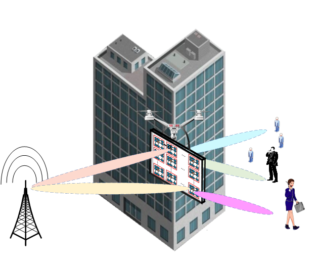
The communication system under study is depicted in Fig. 1. It is worth mentioning that in the system model for the BS-STAR-user path, a novel joint hybrid 3D beamforming BS-subarray and the corresponding subSTAR architecture are proposed for UAV-mounted STAR-aided THz multi-user massive MIMO systems, the realization of which will be detailed in the following sections. The system model we adopted is shown in Fig. 2. The THz transceivers have array-of-subarrays of graphene-based plasmonic nano-antennas [38]. The BS transmitter (TX) having subarrays supports users either with or without STARs. The ith subarray of the BS is a UPA having antenna units. For simplicity and without loss of generality, we let , . Note that is also the number of RF chains, since each BS subarray is controlled by a dedicated RF chain. Due to limited processing power, there is only a single subarray baseband and RF chain consisting of tightly-packed elements at the kth user. For simplicity and without loss of generality, we let , . The number of antenna subarrays is assumed to be higher than for attaining high gains. UPAs are promising for THz communications both in BS and user terminals, since they can accommodate more antenna elements by a two-dimensional subarray for 3D beamforming.
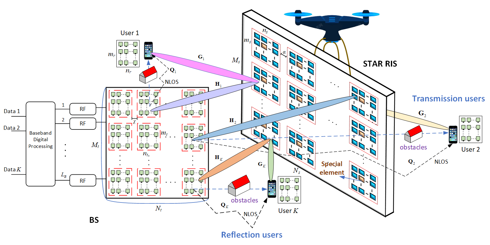
Blockage is commonplace in THz communications. Hence we assume that the line-of-sight (LOS) link from the BS to each user is indeed blocked, and a STAR is applied for improving the link spanning from the BS to the user by reflecting and refracting the signal. The STAR consists of a sub-wavelength UPA having passive reflecting and transmitting elements under the control of a STAR controller. The THz channel is highly frequency-selective, but there are several low-attenuation windows separated by high-attenuation spectral nulls owing to molecular absorption [39]. Therefore, we can adaptively divide the total THz signal bandwidth into numerous sub-bands, say sub-bands. The hth sub-band is centered around frequency and it has a width of . If is small enough, the channel can be regarded as frequency-non-selective and the noise power spectral density appears to be locally flat. Thus, for the hth subband signal, we will discuss the direct path spanning from the BS to the user and that from the BS to the user via STAR, i.e., the BS-STAR-user path.
(1) The direct BS-user path
The received signal of user can be expressed as
| (1) |
where is a vector containing the transmitted symbols of users, so that , where denotes the total initial transmit power and the same power is assigned to each user. In (1), is the THz channel matrix between the BS and user . The LOS components of the direct BS-user links are blocked by obstacles, we thus assume that the direct link channel contains only non-line-of-sight (NLOS) components; is the analog transmit beamforming matrix representing the equal power splitters and phase shifters. For the array-of-subarray structure of (1), is block-diagonal structure and can be expressed as
| (2) |
where is an vector; let denote the element of , , . Still referring to (1), is the baseband digital beamforming matrix used for interference mitigation, and can be expressed as
| (3) |
with
| (4) |
is a vector of the kth user; is the receive analog beamforming vector applied by user ; let denote the element of , , ; is the Gaussian noise vector at user , i.e., , .
(2) The STAR-aided path
The STAR consists of a sub-wavelength UPA having passive elements. According to the subarray structure of the BS, we also partition the STAR into subSTARs. The th subSTAR consists of elements, . Each subSTAR is the dual counterpart of every subarray of the BS. Thus, we have . The adjacent elements are separated by , where is the Surface Plasmon Polariton (SPP) wavelength [40], which is much smaller than , the free-space wavelength. For simplicity and without loss of generality, we let , .
Let the THz channels spanning from the BS to STAR, and from the STAR to user , be denoted by and , respectively. The STAR transmission/reflection matrix is denoted by and the transmission/reflection matrix from the th subSTAR to user is denoted by . Whether the STAR works in the transmission or reflection mode depends on which side of the STAR the user is on. For the subSTAR structure, is an block matrix
| (5) |
where is an matrix; , where , is the phase of the -th transmission/reflection element in the k-th subSTAR, . Without loss of generality, we assume that the number of subSTARs and the k-th subSTAR transmits/reflects the signals for the k-th user. Thus, we propose a joint hybrid 3D beamforming–BS array-of-subarray and the corresponding subSTAR architecture, the implementation details will be given in the following sections. For each subSTAR, either transmission or reflection occurs.
The received signal of user can be expressed as
| (6) |
where is the element channel matrix of the line spanning from the BS to the STAR. Furthermore, is the channel matrix of the line emerging from the STAR to the user k. Observe that can also be expressed in the form of the desired signal and interference terms as follows:
| (7) |
The STAR-aided THz channel is dominated by the LOS path and some indirect BS-STAR rays from NLOS propagation due to reflection and scattering [41] due to the quasi-optical characteristic of THz signals. Let denote the channel matrix of the line spanning from the k-th BS subarray to the k-th subSTAR, while denote the channel matrix of the line spanning from the k-th subSTAR to the k-th user. Thus, and are modeled by
| (8) |
| (9) |
where and represent the LOS components, while and denote the NLOS components; (), ( are the azimuth and elevation AODs (angle of departure) at the -th BS subarray, respectively; (), () are the azimuth and elevation AOAs (angle of arrival) at the -th user, respectively; (), are the azimuth and elevation AOAs from the -th BS subarray to the -th subSTAR, respectively; (), () are the azimuth and elevation AODs from the -th subSTAR to the -th user, respectively; and are the numbers of NLOS components; and denote the corresponding THz LOS complex gains given by
| (10) |
where and are the corresponding THz LOS path-loss, is the absorption coefficient at frequency , is the distance from the BS to the STAR, is the distance from the STAR to the user, both for user , and is the speed of light. Still referring to (8) and (9), and denote the corresponding THz NLOS complex gains.
In Eq. (8) and (9), , and are the antenna array steering vectors at the k-th BS subarray and -th user, respectively:
| (11) | ||||
where and denote the index of the BS antenna element, , . Additionally, is the distance between the BS antenna elements, and represents the wavelength of THz signals. Still referring to (9), we have
| (12) | ||||
where and denote the index of the user antenna element, , ; and is the distance between the user antenna elements.
Explicitly, and in Eq. (8) and (9) are the arrival and departure steering vectors at the -th subSTAR, respectively. They can be expressed as follows:
| (13) | ||||
| (14) | ||||
where and denote the index of the STAR element, , ; and is the distance between the STAR elements within the subSTAR.
Therefore, upon combining (1) and (6), the signal received by user from the BS-user and from the BS-STAR-user channels can be expressed as
| (15) |
The THz channels are sparse and only few paths exists [41]. Moreover, the power difference of the THz signals between the LOS and NLOS path is significant. Specifically, the power of the first-order reflected path is attenuated by more than 10 dB on average compared to the LOS path and that of the second-order reflection by more than 20 dB [41], so THz channels are LOS-dominant. As such, we will focus on the LOS path of the THz signal when exploring the spatial multiplexing condition and optimal position of the UAV-mounted STAR. Furthermore, considering the beamforming gain of the transceivers and the gains of the STAR, the received power of the BS-user link in (15) is much lower than that of the BS-STAR-user link.
II-B Problem Formulation
The problem is formulated as joint design of the THz BS and STAR (with the optimal position) with 3D beamforming (both active and passive) to achieve the optimal performance of multi-user THz massive MIMO systems for diverse communication environments with different obstacles.
The system performance in terms of the achievable sum-rate of the users can be expressed by
| (16) |
where we have
| (17) |
With GI quantum sensing, we can obtain the information of the communication environment including the obstacles and positions of the potential users. The details will be given in the following sections. The 3D image of the environment obtained from GI is discretized due to limited resolutions, which can be easily transformed into 3D grid including vertices and edges, where belongs to the Euclidean space . The grid granularity is approximately equal to the resolution of GI 3D imaging. Then we perform K-means to obtain the user clustering and centroids of the user clusters. For simplicity and without loss of generality, we focus on one user cluster here. The 3D positions of the BS and centroid of the user cluster, denoted by and , respectively, are transformed into vertices of . Let denote the position of the UAV-mounted STAR. The set of obstacles is represented by .
Our objective is to maximize the sum rate of all the users. The optimization problem is formulated as
| (18) |
Constraint C1 represents the STAR unit-modulus constraint of phase shift matrices; Constraint C2 restricts that the positions of the BS, user and STAR should be inside the considered environment ; Constraint C3 restricts that the sum LOS distance from the BS to the STAR and from the STAR to the user should be larger than the direct distance between the BS and the user; Constraint C4, and C5 restricts that , are the LOS path from to , and from to , respectively; Constraint C6 restricts that the cascaded LOS path (where paths and are connected) assisted by UAV-mounted STAR should not intersect the interior of any obstacle ; Constraint C7 restricts that the LOS path from the BS to the user is obstructed by the obstacles ; Constraint C8 represents the conditions that the analog transmit beamforming and baseband digital beamforming needs to satisfy; Constraint C9 restricts the the minimum flight altitude and the maximum flight altitude of the UAV which may be imposed by government regulations.
III Conditions of Spatial Multiplexing for the Proposed Architecture
In this section, we discuss the conditions of achieving high multiplexing gains for the proposed STARs-aided THz architecture. As the propagation of signals at THz frequencies is “quasi-optical”, the LOS path dominates the channel complemented only by a few non-LOS (NLOS) reflected rays due to the associated high reflection loss. Thanks to the beamforming gain and flexible placement of STARs, a LOS path may be present between each pair of the BS subarrays, the subSTAR and the user’s receiver arrays.
We first consider the BS-STAR channel. Without loss of generality, we assume symmetry in the remainder of the paper, i.e., , . Thus, the BS contains subarrays and the STAR contains subSTARs. The capacity is maximized when all columns of are orthogonal. Because STARs can transmit and reflect at the same time, they can provide omnidirectional coverage compared to reflection-only RISs, and thus a STAR can simply be placed in front of BS without an angle. Based on [42], we have the following Lemma for STAR-aided signal transmission/reflections.
Lemma 1.
For STAR-aided systems, the optimal subSTARs and BS subarray design condition should satisfy
| (19) |
for integer values of , and , , where is the minimal common multiples of ; and are the optimal distances between two adjacent BS subarrays and subSTARs for the th THz subband, respectively; is the distance between the centers of the STAR and BS arrays.
Proof:
The proof is similar to Theorem 1 in [42], hence it is omitted here. ∎
The separation of elements in the BS subarrays or subSTARs may be achieved via spatial interleaving. Moreover, the required spacing can be realized by choosing the right elements belonging to each BS subarray or subSTAR. Each BS subarray associated with the corresponding subSTAR may focus on a specific individual subband of the THz signal and can also be tuned flexibly according to the different user distances.
Let us now consider the channels spanning from the subSTARs to the users. At the receiver side, since each user has an antenna array and is generally separated, the distance between two adjacent user antenn arrays is usually large. Naturally, we cannot impose any constraints on the user positions, which tend to be random. Therefore, we must resort to exploiting the frequency selectivity of the THz channels for spatial multiplexing. According to [41], the THz channels have limited angular spread of about . As the coverage area of a STAR is greatly expanded to almost 360 degrees, the requirement of such spatial independence becomes much easier to satisfy than a reflection-only RIS. Since the beam steering vectors associated with completely different angles of large-scale antennas are nearly orthogonal, for the channels spanning from the ith and the kth subSTAR to user k, we have
| (20) |
As the STAR may be regarded as a passive large-scale antenna array, the channel from the STAR to the user can be nearly orthogonal, hence spatial multiplexing gains can be achieved. For users that are close enough to be within the angular spread, the pre-scanning and grouping technique of [41] can be adopted.
IV Proposed Quantum Sensing based Joint 3D Beam Training for the UAV-mounted STAR aided THz multi-user MIMO Systems
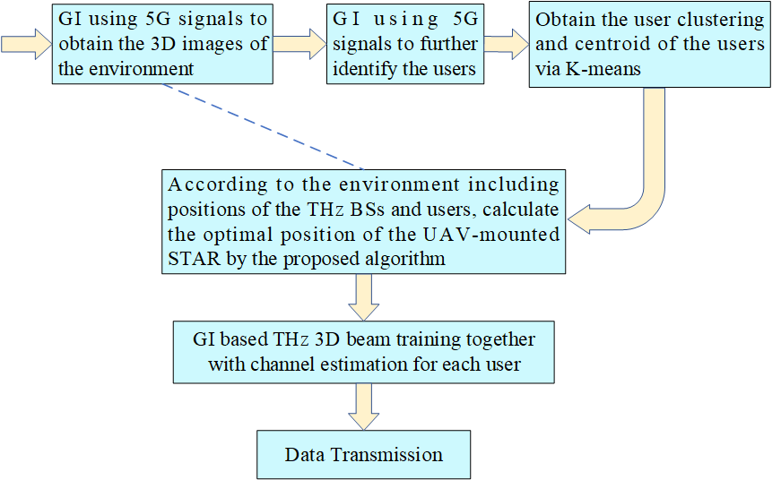
In order to realize the proposed joint hybrid 3D beamforming BS array-of-subarray and the corresponding subSTAR architecture as well as the effective communication environment sensing, in this section, we propose a novel quantum sensing, i.e., Ghost Imaging based beam training scheme for UAV-mounted STAR aided THz multi-user MIMO systems, the flow diagram of which is shown in Fig. 3. The environment information obtained by GI allows us to expedite the channel estimation and beamforming processes. We first conduct GI using 5G BSs to obtain the 3D images of the environment and users. Then we perform K-means to obtain the user clustering and centroid of the users. For simplicity and without loss of generality, we focus on one user cluster here. According to the environment including positions of the THz BSs and users, the optimal position of the UAV-mounted STAR can be calculated by the proposed algorithm. We also propose a semi-passive structure of the STAR for channel estimation. Based on the estimated separated channel information, active and passive beamforming are carried out and data transmission begins. We will explain in detail each block function in the following subsections.
IV-A Ghost Imaging by surrounding 5G BSs
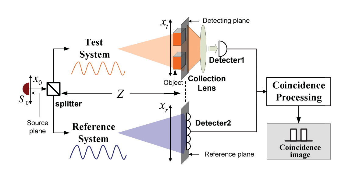
Multiple communication systems must coexist in future communication scenarios in which the near-ubiquitous surrounding 5G BSs can be used to assist in Ghost imaging for low-cost ISAC systems. Thus we first conduct GI by surrounding 5G downlink signals to obtain the 3D images of the environment including users and obstacles. Inspired by the classical coincidence imaging implemented in optical system as shown in Fig. 4, an instantaneous microwave radar imaging technique called Radar Coincidence Imaging (RCI) [35] can obtain high-resolution images of target focus without motion limitation.
The high resolution reconstruction of the target can be achieved in the GI framework by mimicking the radiation element on the surface of the incoherent light source with an antenna emitting randomly modulated signals. Microwave GI or association imaging is to generate radiation field distribution with time-varying and space-varying characteristics in the microwave frequency band, form differential irradiation on the imaging area, associate the target echo signal with the radiation field, and reconstruct the target image. Because the resolution of the target is derived from the modulation of the transmitted signal, it breaks the dependence of the traditional microwave imaging technology on the observation angle and Doppler, and does not need the relative motion between the imaging system and the target.
Microwave GI can be modeled as a linear model, and imaging reconstruction can be regarded as solving a linear inverse problem. According to the radiation field reference matrix and the properties of the target scattering coefficient vector, multiple methods can be used to obtain the estimation of the target scattering coefficient vector, so as to reconstruct the target image. First, consider the EM field on plane radiated by 5G BSs, then we have
| (21) |
where is the EM state of the single point on the imaging plane , , is the propagation delay from the ith BS to , and is the propagation attenuation. The randomness of the propagation delays from these non-uniformly distributed BSs further enhances the spatial incoherence of the generated EM field.
To reconstruct the image of objects, the sampling interval should be set much larger than the coherence time to guarantee the incoherence between any two samples. That is, , where , is the bandwidth of the 5G signals.
According to Born’s Approximation, we divide the imaging area equally into sub-planes with rows and columns, where . It is worth mentioning that although we consider two-dimensional image planes here, the technique of tomographic imaging can be used to construct three-dimensional images.
The illumination matrix on the surface of the target plane after transmissions from 5G BSs can be expressed by
| (22) |
where , , is the EM field at the corresponding pixel in the th measurement.
Then the received signal can be expressed as
| (23) |
where
| (24) |
| (25) |
| (26) |
is the corresponding scattering coefficient, is the receiving signal from the th illumination and is the propagation attenuation from the pixel to the receiver. The image reconstruction of the object can be achieved by solving the following optimization problem
| (27) |
Optimization algorithms, e.g., Gradient Projection (GP), can be used to solve it. Here we adopt the minimum mean squared error (MMSE) method.
The spatial resolution of microwave GI is restricted by the physical size of the coherent size, the boundary of which in the background field can be expressed as [29]
| (28) |
where is the size of the source, is the wavelength, and is the normal distance from the source to the target objects.
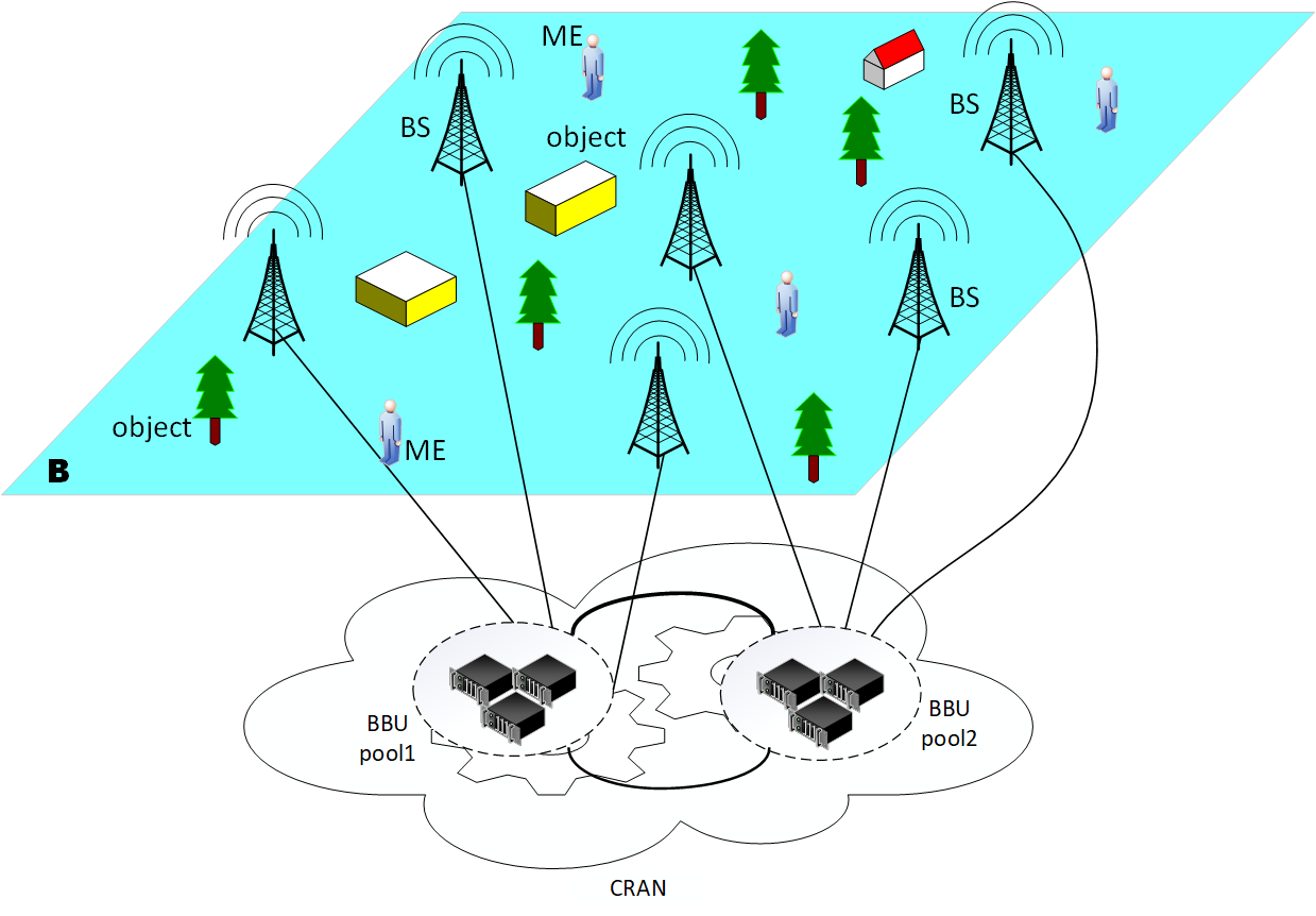
Here we propose to utilize the CRAN structure of the 5G BSs, which can further enlarge the size of the source. The three-dimensional (3D) 5G-based GI scenario based on CRAN is depicted in Fig. 5. The investigation area is inhomogeneous with several objects to be imaged. The objects in are distinguished by their scattering coefficients. The investigation area is illuminated by 5G BSs. The height from BSs to are assumed to be identical. Let denote the signals transmitted from the th BS, and reflected signals from objects are collected by a single receiving BS located in the centre of . THz BSs are co-located with 5G BSs, or their core networks can share information.
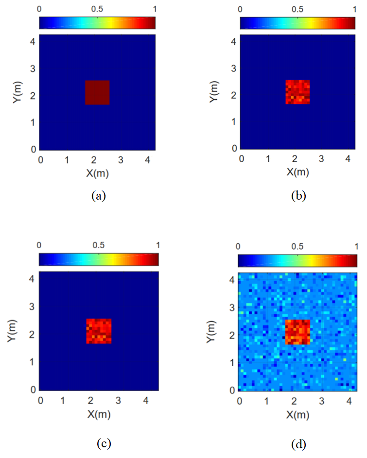
Thus the resolution of the 5G GI can be much higher than that of the traditional LTE GI. The simulation results are shown in Fig. 6 with a single square shaped target located in the center of the investigation area as an example. As shown in Fig. 6 (c), (d) and (e), the GI reconstruction of the object is achieved with much improved resolution () compared to that of the LTE GI [36] () under the different SNR. The edges of the objects or users detected can be adopted to assist the optimal UAV-mounted STAR position finding as well as the joint active and passive beam forming.
IV-B Joint Active and Passive Beamforming Design of the UAV-mounted STAR
The BS utilizes the angle information of the BS-RIS link to design the active beamforming. For THz signals, the pencil-like beams necessitate perfect line-of-sight (LoS) alignment between the transmitter and receiver antennas. The phase shifts of the signals reflected/transmitted from STARs can be proactively adjusted to establish virtual LoS links. Without loss of generality, we assume that the k-th user is assisted by the k-th subSTAR. Thus, the active beamforming designed for the -th user should be aligned to the -th subSTAR. As such, the transmit beam of the -th BS subarray is designed as
| (29) |
where is the transmit power of the k-th BS subarray. When the transmit power is equally divided among BS subarrays corresponding to different users, we have =.
The received beam of the -th user is given by
| (30) |
Based on [42], we design the optimal STAR phase shift beam as
| (31) |
where , and is the estimation of .
The AOAs and AODs can be calculated from the BS and user positions obtained by GI sensing, and the optimal position of UAV-mounted STAR which will be acquired in proposed Algorithm 1 presented later. Then the pre-specified codebook designed with directional beams associated with the corresponding AOAs/AODs can be selected, thus GI based beam training is achieved.
To further enhance the beamforming gain, the instantaneous channel state information (CSI) can be obtained by e.g., tensor-based channel estimation [21]. All the beam training and channel estimation can be carried out in parallel for every pair of BS-subarray, subSTAR and user array. Furthermore, we propose a semi-passive STAR structure as shown in Fig. 2 and the channel estimation ambiguity elimination scheme for separate channel estimation, the details of which can be found in Appendix A, where it is shown that the ambiguity in the separated channel and may affect the optimal passive beamforming design. Therefore, it can be noted that the separate channel estimation instead of cascaded channel estimation is adopted above for the optimal active and passive beamforming design.
IV-C Design of the BS’s Digital Precoder
Following the beam training and channel estimation, we will now design the digital transmit precoder (TPC) for interference cancellation among different users. The digital TPC can be designed as follows. Let
| (32) |
where denote the estimated channel of . Specifically, the MMSE TPC is formulated as
| (33) |
IV-D Problem Reformulation and Proposed Solution
According to the orthogonality of different users arranged by the subSTAR and subarray of the BS, which is achieved by the conditions shown in Section III, as well as the previous digital TPC, we have
| (34) |
Therefore, we arrive at:
| (35) |
Then the optimization problem in (18) becomes
| (36) | ||||
| (37) |
which is a non-convex combinatorial optimization problem which cannot be solved efficiently via standard optimization methods and the global optimum is challenging to find. To address (36), we decouple the optimization into three sub-problems, i.e., the joint active and passive beamforming, the design of digital precoding, and position optimization of the UAV-mounted STAR.
Let us represent the kth subSTAR-aided cascaded channel by
| (38) |
For far-field beamforming over the STAR-aided THz channel, the channel power of of the kth user can be expressed as
| (39) |
where is the distance from the STAR to the user k and . Let denote the the distance from the STAR to the centroid of the user cluster, i.e., =. Let . Based on the previous obtained optimal active and STAR passive beamforming in (29), (30), (31) and (33) for , , and digital precoding , respectively, we can now opt for the last sub-problem, i.e., the end-to-end THz LoS channel power optimization through optimizing the position of the UAV-mounted STAR :
| (40) |
By discarding irrelevant constant terms and taking logarithm of (40), the optimization problem of (40) is equivalent to
| (41) |
As is about [43], generally for far-field, [42], thus is about , whereas . Therefore, we have , which makes (41) equivalent to
| (42) |
We then need to find out the optimal position of the UAV-mounted STAR to solve the problem (42). Although the shortest paths in deterministic 2D environments can be found by performing algorithms such as Dijkstra, finding the shortest paths in 3D environments with polyhedral obstacles is NP-hard [44]. An “any-angle” find-path algorithm called Theta* can finds shorter paths on square grids than both A* and A* PS with a similar runtime [44]. Theta* typically finds much shorter paths than that by propagating information along graph edges without constraining paths to be formed by graph edges. Lazy Theta* [44] is a variant of Theta* using lazy evaluation to perform only one line-of-sight check per expanded vertex with slightly more expanded vertices. Lazy Theta* guarantees the optimal path-finding and performs faster than Theta* on cubic grids, with one order of magnitude fewer LOS checks and no increase in path length. Considering that and are LOS paths and Lazy Theta* can detect any optimal LOS path, we tactfully utilize Lazy Theta* to find the optimal position (with the path lengths set to logarithm of the Euclidean length) under the constraints of . Upon execution, Algorithm 1 will output , the optimal position of the UAV mounted STAR. Based on (42), the proposed UAV-mounted STAR position finding algorithm is proposed as follows.
1 Input , ,
2 ;
3 ;
4 ;
5 ;
6 while do
7 ;
8 if NOT then
9
;
10
11 end if;
12 if then
13 output the optimal position of the STAR ;
14 end if
15 ;
16 foreach do
17 if then
18 if then
19 ;
20 ;
21 end if
22 ;
23 if then
24 ;
25
26 end if
27 if then
28 if then
29 ;
30 end if
31 ;
32 end if
33 end if
34 end for
35 end while
In the algorithm, and are the start and goal vertex of the search, respectively; is the length of the shortest path from the start vertex to found so far; is the straight-line distance between vertices and , and is true if and only if they have line of sight; inserts vertex with key into the priority queue ; removes vertex from ; removes a vertex with the smallest key from and returns it; is used to extract the path at the end of the search; approximates the goal distance of the vertex ; is the set of neighbors of vertex that have line of sight to .
Therefore, with the knowledge of the positions of the BS, users and UAV-mounted STAR, joint 3D beam training can be carried out along with channel estimation for each user.
IV-E Complexity Analysis
In this subsection, we compare the search complexity of our proposed beam training schemes to those of others [22]. The results are shown in Table I. Compared to other schemes, the search time of our proposed scheme is negligible and irrelevant to the total number of the STAR elements, . By contrast, the complexity of the benchmarks increases with the number of the STAR elements.
| Beam training schemes | Applicable to RIS-aided system | Applicable to THz | Search time for RIS-aided system |
|---|---|---|---|
| Exhaustive search | Yes | Yes | |
| One-side search [45] | No | No | |
| Adaptive binary-tree search [52] | No | No | |
| Two-stage training scheme [53] | No | Yes | |
| Tree dictionary (TD) and PS deactivation (PSD) codebook based search [22] | Yes | Yes | (TD) or (PSD) |
| Proposed GI-based 3D beam training scheme | Yes | Yes | Negligible and not related to |
V Simulation Results and Discussions
In this section, we evaluate the performance of our Ghost Imaging-based beam training and channel estimation scheme proposed for the UAV-mounted STAR-aided THz multi-user MIMO systems. At the BS, each RF chain is connected to a single sub-arrray and each subarray corresponds to a user. As there is a low-attenuation THz transmission window at 350 GHz [39], we consider the THz frequency band at 350 GHz in the simulations. The number of paths between the user and the BS is set to 3 due to the sparsity of the THz channels [41]. The BS and user positions are sensed by GI and the channel conditions of (20) are satisfied. The BS initially does not know the CSI and the beam training and channel estimation is conducted based on our proposed scheme.
| Parameters | Values |
|---|---|
| Duplex | TDD |
| Central Frequency | 2.6 GHz |
| Sub-carriers Spacing | 15 KHz |
| CP Type | Normal |
| Parameters | Symbols | Values |
|---|---|---|
| Center frequency of the subband | GHz | |
| Noise power | −75 dBm | |
| Subband Bandwidth | 1 GHz | |
| Absorption Coefficient | 2.13e-6 [43] | |
| Number of Users | 4 | |
| Position of the center of the BS | (7, 13, 7) | |
| Positions of the users in the focused cluster | (11, 8, 1), (13, 9, 0.94), (12, 8, 1.5), (14, 7, 0.8) | |
| Position of the centroid of the focused user cluster | (12, 8, 1) |
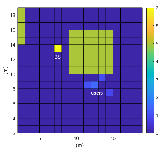
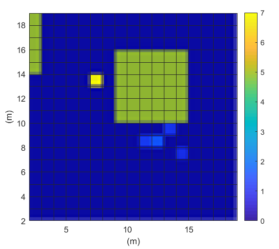
The simulation settings of the 5G GI are given in Table II. The originally investigated communication environment including the users and the corresponding 5G GI reconstructed results are shown in Fig. 7 (a)-(d), respectively. A nodes grid representing a known cluttered environment is created as shown in Fig. 7 (a). The grid is populated with obstacles representing buildings in an urban area. Location and size are randomly assigned to all obstacles. The data representation of the environment is a simple matrix with elements having discrete values from 0 to 20 m, which is compatible with Digital Elevation Models (DEM), a 3D representation of the terrain commonly adopted in topography. The color bars indicate the heights of the objects in the image. The BS and users are also specified in the image. The reconstructed 5G Ghost Imaging of the communication environment is presented in Fig. 7(b) . The original image of a user, which can be regarded as the enlarged version of the users in Fig. 7(a), and the corresponding reconstructed 5G GI image are shown in Fig. 7(c) and (d), respectively.


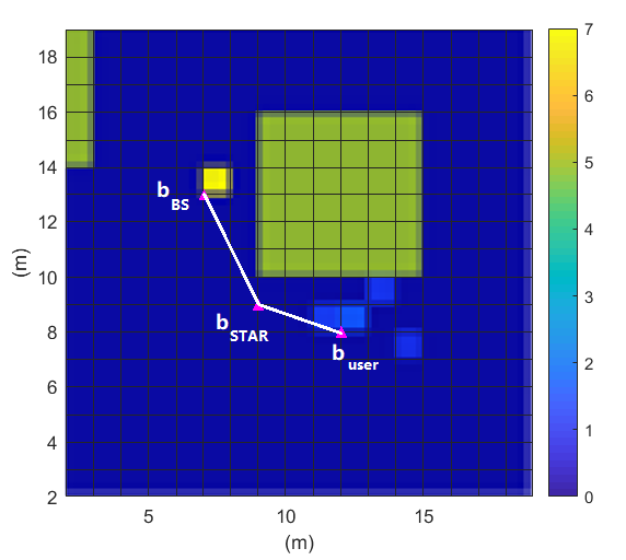
The 3D positions of the BS, users and centroid of the focused user cluster are determined via GI and K-means, and shown in Table III. For clarity, user clusters other than the focused one are not shown in Fig. 7. There are 4 users in the focused cluster, at different positions. There are no LOS paths between the BS and users. Based on these information and communication environment including obstacles sensed by 5G GI, the optimal position of the UAV STAR obtained by our proposed Algorithm 1 is (9, 9, 3), as shown in Fig. 8.
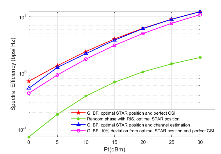
The simulation parameters of the STAR-aided THz 3D beamforming for multi-user massive MIMO systems are also given in Table III. It is assumed that each BS antenna subarray is a UPA and each user is equipped with one RF chain associated with a UPA array. Each subSTAR is also a UPA. For the STAR-aided channel, the distance between the BS and the STAR is 6 m while the distances between the STAR and the users are 3 m, 4.5 m, 3.5 m and 5.8 m, respectively. The simulation results are shown in Fig. 9 (a)-(c). With the proposed semi-passive structure of STAR, the separated channels are estimated efficiently as well as the cascaded channel. Observe that the scheme with GI, the optimal STAR position and perfect CSI achieves the highest spectral efficiency. The proposed scheme combining GI and tensor based channel estimation together with the optimal STAR position can effectively increase the spectral efficiency with the increase of transmitting power. To demonstrate the advantage of the proposed optimal STAR position find algorithm, we have chosen a STAR position (8, 8, 2.1) which is 10% deviated from the optimal one but satisfies the rest of the constraints such as and . The distance between the BS and the STAR is now 7.1 m while the distances between the STAR and the users are 3.2 m, 5.2 m, 4.0 m and 6.2 m, respectively. It can be seen that the spectral efficiency of the UAV-mounted STAR at the deviated position even with perfect CSI is much lower than that at the optimal position. The performance of STAR-aided channel associated with random phase has the lowest spectral efficiency.


Then we increase the BS antenna subarray, STAR subarray and user array all to UPA. The simulation results are shown in Fig. 10. It can be seen that with the increase of the STAR elements, the channel estimation accuracy is further improved compared to the previous case. Moreover, the system performance of the proposed scheme is improved more significantly compared to that at the 10% deviation position even with perfect CSI.


We continue to increase the BS antenna subarray, STAR subarray and user array all to UPA. The simulation results are shown in Fig. 11. With the increase of the STAR elements, the channel estimation accuracy is further improved compared to the previous case. The system performance of the proposed scheme is also improved, which is almost comparable to the perfect CSI baseline. To sum up, the proposed scheme can improve the spectral efficiency on average by 14.26%, 18.35% and 60.60% for the three configurations, respectively, compared to that at the 10% deviation position even with perfect CSI.


VI Conclusions
A novel Ghost Imaging-based joint 3D beam training scheme was proposed in this paper for UAV-mounted STAR aided THz multi-user massive MIMO systems. To maximize the average achievable sum-rate of the users, the proposed BS sub-array and sub-STAR spatial multiplexing architecture, optimal active and passive beamforming, digital precoding, and optimal position of the UAV-mounted STAR were jointly investigated. The surrounded 5G downlink signals are utilized for GI. Our simulation results show that the spectral efficiency of our proposed system is much higher than that at the deviated position or with the STAR at random phases. Our proposed GI based joint 3D beamforming architecture with the optimal position finding algorithm has practical potential for emerging UAV-mounted STAR-aided THz applications such as integrated networks of terrestrial links, UAVs, and satellite communication systems. As our future work, other forms of ISAC will be explored for UAV-mounted STAR-aided THz multi-user massive MIMO systems.
VII Appendix A
Ambiguity Elimination for Separation Channel Estimation
When combined with tensor-based channel estimation, the received signal for user k can be expressed by
| (43) |
where is the vector of the transmitted pilot signals for the user k at time . The channel training time is divided into blocks, where each block has time slots so that . The signal part of the equation (43) can be expressed by
| (44) |
where denotes a diagonal matrix holding the -th row of the STAR phase shift matrix on its main diagonal, , , and are the -th user pilot matrix, respectively. The matrix can be viewed as the -th frontal matrix slice of a three-way tensor following a PARAFAC decomposition.
As long as the sufficient conditions [21] are satisfied , the uniqueness of the nested PARAFAC decomposition means that two quintuplets of matrix factors are linked by
| (45) |
| (46) |
| (47) |
where , and are diagonal matrices, and is a permutation matrix. Taking into account the knowledge of the phase shift matrices of the subSTAR , the ambiguity relation (46) gives , then (45) and (47) become
| (48) |
| (49) |
The only remaining ambiguities exist in the diagonal matrices or . If we know any row of or , e.g., the -th row, these scaling ambiguities can then be eliminated by the following operations:
| (50) |
| (51) |
where and denote the estimated values of and at convergence of the BALS algorithms, denotes the the -th row of matrix .
Compare to the cascaded channel estimation cases, we have the remark as follows:
Remark 1: The ambiguity in the separated channel and may affect the optimal passive beamforming design.
According to (45) to (47), if the phase shift matrices of the subSTAR are unknown, then any phase shift matrices satisfied
| (52) |
can also be the pursued phase shift matrices. Therefore, it is necessary to eliminate the ambiguities in the channel and .
Here we propose a semi-passive STAR architecture with each subSTAR being composed of one special STAR element equipped with a receiving RF chain, which can operate in both sensing and reflecting / transmitting modes as illustrated in Fig. 2. The special STAR element is able to directly sense the one-hop channels by observing the training signal at the STAR end. Resorting to the special STAR elements, we will be able to obtain one of the rows of or , e.g., the -th row. According to (50) and (51), the ambiguities in the channel and can then be eliminated.
References
- [1] X. Ma, Z. Chen, W. Chen, Z. Li, Y. Chi, C. Han, and S. Li, “Joint Channel Estimation and Data Rate Maximization for Intelligent Reflecting Surface Assisted Terahertz MIMO Communication Systems,” IEEE Access, vol. 8, pp. 99 565–99 581, 2020.
- [2] C. Lin and G. Y. Li, “Energy-Efficient Design of Indoor mmWave and Sub-THz Systems with Antenna Arrays,” IEEE Trans. Wireless Commun., pp. 1–1, 2016.
- [3] C. Pan, H. Ren, K. Wang, M. Elkashlan, A. Nallanathan, J. Wang, and L. Hanzo, “Intelligent Reflecting Surface Aided MIMO Broadcasting for Simultaneous Wireless Information and Power Transfer,” IEEE J. Select. Areas Commun., vol. 38, no. 8, pp. 1719–1734, Aug. 2020.
- [4] Q. Wu and R. Zhang, “Intelligent Reflecting Surface Enhanced Wireless Network via Joint Active and Passive Beamforming,” IEEE Trans. Wireless Commun., vol. 18, no. 11, pp. 5394–5409, Nov. 2019.
- [5] X. Wang, P. Wang, M. Ding, Z. Lin, F. Lin, B. Vucetic, and L. Hanzo, “Performance analysis of terahertz unmanned aerial vehicular net- works,” IEEE Transactions on Vehicular Technology, vol. 69, no. 12, pp. 16 330–16 335, 2020.
- [6] Y. Liu, W. Li, Z. Lin, “A Dynamic Subarray Structure in Reconfigurable Intelligent Surfaces for TeraHertz Communication Systems”, Proceedings of IEEE Conference on Standards for Communications and Networking (CSCN), November 2022, Thessaloniki, Greece.
- [7] W. Du, G. Chen, P. Xiao, Z. Lin, C. Huang. W. Hao, and R. Tafazolli, “Weighted Sum-Rate and Energy Efficiency Maximization for Joint ITS and IRS Assisted Multiuser MIMO Networks,” in IEEE Transactions on Communications, 2022, doi: 10.1109/TCOMM.2022.3213356.
- [8] Z. Chu, P. Xiao, D. Mi, W. Hao, Z. Lin, Q. Chen, and R. Tafazolli, “Wireless powered intelligent radio environment with non-linear energy harvesting,” IEEE Internet of Things Journal, vol. 9, no. 18, pp. 18130-18141, 15 Sept.15, 2022, doi: 10.1109/JIOT.2022.3162761.
- [9] S. Zhang and R. Zhang, “Capacity Characterization for Intelligent Reflecting Surface Aided MIMO Communication,” IEEE J. Select. Areas Commun., vol. 38, no. 8, pp. 1823–1838, Aug. 2020.
- [10] J. Ye, S. Guo, and M.-S. Alouini, “Joint Reflecting and Precoding Designs for SER Minimization in Reconfigurable Intelligent Surfaces Assisted MIMO Systems,” IEEE Trans. Wireless Commun., vol. 19, no. 8, pp. 5561–5574, Aug. 2020.
- [11] Y. Hu, P. Wang, Z. Lin, and M. Ding, “Performance Analysis of Reconfigurable Intelligent Surface Assisted Wireless System With Low-Density Parity-Check Code,” IEEE Commun. Lett., vol. 25, no. 9, pp. 2879–2883, Sep. 2021.
- [12] H. Guo, Y.-C. Liang, J. Chen, and E. G. Larsson, “Weighted Sum-Rate Maximization for Reconfigurable Intelligent Surface Aided Wireless Networks,” IEEE Trans. Wireless Commun., vol. 19, no. 5, pp. 3064–3076, May 2020.
- [13] X. Wei, D. Shen, and L. Dai, “Channel Estimation for RIS Assisted Wireless Communications-Part I: Fundamentals, Solutions, and Future Opportunities,” IEEE Commun. Lett., vol. 25, no. 5, pp. 1398–1402, May 2021.
- [14] A. M. Elbir, A. Papazafeiropoulos, P. Kourtessis, and S. Chatzinotas, “Deep Channel Learning for Large Intelligent Surfaces Aided mm-Wave Massive MIMO Systems,” IEEE Wireless Commun. Lett., vol. 9, no. 9, pp. 1447–1451, Sep. 2020.
- [15] S. Shaham, M. Ding, M. Kokshoorn, Z. Lin, S. Dang, and R. Abbas, “Fast Channel Estimation and Beam Tracking for Millimeter Wave Vehicular Communications,” IEEE Access, vol. 7, pp. 141 104–141 118, 2019.
- [16] S. Liu, Z. Gao, J. Zhang, M. D. Renzo, and M.-S. Alouini, “Deep Denoising Neural Network Assisted Compressive Channel Estimation for mmWave Intelligent Reflecting Surfaces,” IEEE Trans. Veh. Technol., vol. 69, no. 8, pp. 9223–9228, Aug. 2020.
- [17] Y. Chen, M. Ding, D. L opez-Perez, X. Yao, Z. Lin, and G. Mao, “On the theoretical analysis of network-wide massive mimo performance and pilot contamination,” IEEE Transactions on Wireless Communi- cations, vol. 21, no. 2, pp. 1077–1091, 2022.
- [18] Z. Lin, B. Vucetic, J. Mao, “Ergodic capacity of LTE downlink multiuser MIMO systems”, 2008 IEEE International Conference on Communications, 3345–3349.
- [19] Y. Chen, M. Ding, D. L opez-Perez, X. Yao, Z. Lin, and G. Mao, “On the theoretical analysis of network-wide massive mimo performance and pilot contamination,” IEEE Transactions on Wireless Communi- cations, vol. 21, no. 2, pp. 1077–1091, 2022.
- [20] G. Mao, Z. Lin, X. Ge, Y. Yang, “Towards a simple relationship to estimate the capacity of static and mobile wireless networks”, IEEE transactions on wireless communications 12 (8), 2014, 3883–3895
- [21] G. T. de Araujo, A. L. F. de Almeida, and R. Boyer, “Channel Estimation for Intelligent Reflecting Surface Assisted MIMO Systems: A Tensor Modeling Approach,” IEEE J. Sel. Top. Signal Process., vol. 15, no. 3, pp. 789–802, Apr. 2021.
- [22] B. Ning, Z. Chen, W. Chen, Y. Du, and J. Fang, “Terahertz Multi-User Massive MIMO With Intelligent Reflecting Surface: Beam Training and Hybrid Beamforming,” IEEE Trans. Veh. Technol., vol. 70, no. 2, pp. 1376–1393, Feb. 2021.
- [23] F. Liu, Y. Cui, C. Masouros, J. Xu, T. X. Han, Y. C. Eldar, and S. Buzzi, “Integrated Sensing and Communications: Toward Dual-Functional Wireless Networks for 6G and Beyond,” IEEE J. Select. Areas Commun., vol. 40, no. 6, pp. 1728–1767, Jun. 2022.
- [24] F. Liu, C. Masouros, A. Li, H. Sun, and L. Hanzo, “MU-MIMO Communications With MIMO Radar: From Co-Existence to Joint Transmission,” IEEE Trans. Wireless Commun., vol. 17, no. 4, pp. 2755–2770, Apr. 2018.
- [25] K. Pang, Z. Lin, Y. Li, B. Vucetic, “Joint network-channel code design for real wireless relay networks”, the 6th International Symposium on Turbo Codes & Iterative Information, 2010, 429–433.
- [26] Z. Lin, A. Svensson, “New rate-compatible repetition convolutional codes”, IEEE Transactions on Information Theory 46 (7), 2651–2659
- [27] J. Yue, Z. Lin and B. Vucetic, "Distributed Fountain Codes With Adaptive Unequal Error Protection in Wireless Relay Networks," in IEEE Transactions on Wireless Communications, vol. 13, no. 8, pp. 4220-4231, Aug. 2014, doi: 10.1109/TWC.2014.2314632.
- [28] W. Yuan, F. Liu, C. Masouros, J. Yuan, D. W. K. Ng, and N. Gonzalez-Prelcic, “Bayesian Predictive Beamforming for Vehicular Networks: A Low-Overhead Joint Radar-Communication Approach,” IEEE Trans. Wireless Commun., vol. 20, no. 3, pp. 1442–1456, Mar. 2021.
- [29] X. Wang and Z. Lin, “Microwave Surveillance Based on Ghost Imaging and Distributed Antennas,” Antennas Wirel. Propag. Lett., vol. 15, pp. 1831–1834, 2016.
- [30] X. Wang and Z. Lin, “Nonrandom microwave ghost imaging,” IEEE Transactions on Geoscience and Remote Sensing, vol. 56, no. 8, pp. 4747–4764, 2018.
- [31] R. Luo, Z. Zhang, X. Wang, and Z. Lin, “Wi-fi based device-free microwave ghost imaging indoor surveillance system,” in 2018 28th International Telecommunication Networks and Applications Conference (ITNAC), 2018, pp. 1–6.
- [32] X. Wang and Z. Lin, “High-resolution through-wall ghost imaging algorithm using chaotic modulated signal,” 2015 IEEE International Conference on Acoustics, Speech and Signal Processing (ICASSP), 2015, pp. 1642-1646, doi: 10.1109/ICASSP.2015.7178249.
- [33] X. Wang, Z. Bo, Z. Lin, W. Gong, B. Vucetic, and S. Han, “Error-Control-Coding Assisted Imaging”. arXiv preprint arXiv:1809.06853 (2018).
- [34] S. Liu, C. Deng, C. Wang, Z. Bo, S. Han and Z. Lin, "Microvibration Modes Reconstruction Based on Micro-Doppler Coincidence Imaging," in IEEE Transactions on Geoscience and Remote Sensing, vol. 60, pp. 1-16, 2022, Art no. 2008316, doi: 10.1109/TGRS.2022.3223649.
- [35] Dongze Li, Xiang Li, Yuliang Qin, Yongqiang Cheng, and Hongqiang Wang, “Radar Coincidence Imaging: an Instantaneous Imaging Technique With Stochastic Signals,” IEEE Trans. Geosci. Remote Sensing, vol. 52, no. 4, pp. 2261–2277, Apr. 2014.
- [36] Z. Zhang, R. Luo, X. Wang, and Z. Lin, “Microwave Ghost Imaging via LTE-DL Signals,” in 2018 International Conference on Radar (RADAR). Brisbane, QLD: IEEE, Aug. 2018, pp. 1–5.
- [37] H. Niu, Z. Chu, F. Zhou, and Z. Zhu, “Simultaneous Transmission and Reflection Reconfigurable Intelligent Surface Assisted Secrecy MISO Networks,” IEEE Commun. Lett., vol. 25, no. 11, pp. 3498–3502, Nov. 2021.
- [38] I. F. Akyildiz and J. M. Jornet, “Realizing Ultra-Massive MIMO (1024*1024) communication in the (0.06-10) Terahertz band,” Nano Communication Networks, vol. 8, pp. 46–54, Jun. 2016.
- [39] A. Moldovan, M. A. Ruder, I. F. Akyildiz, and W. H. Gerstacker, “LOS and NLOS channel modeling for terahertz wireless communication with scattered rays,” in 2014 IEEE Globecom Workshops (GC Wkshps). Austin, TX, USA: IEEE, Dec. 2014, pp. 388–392.
- [40] H. Sarieddeen, M.-S. Alouini, and T. Y. Al-Naffouri, “Terahertz-Band Ultra-Massive Spatial Modulation MIMO,” IEEE J. Select. Areas Commun., vol. 37, no. 9, pp. 2040–2052, Sep. 2019.
- [41] C. Lin and G. Y. Li, “Adaptive Beamforming With Resource Allocation for Distance-Aware Multi-User Indoor Terahertz Communications,” IEEE Trans. Commun., vol. 63, no. 8, pp. 2985–2995, Aug. 2015.
- [42] X. Wang, Z. Lin, F. Lin, and L. Hanzo, “Joint Hybrid 3D Beamforming Relying on Sensor-Based Training for Reconfigurable Intelligent Surface Aided TeraHertz-Based Multiuser Massive MIMO Systems,” IEEE Sensors J., vol. 22, no. 14, pp. 14 540–14 552, Jul. 2022.
- [43] X.-W. Yao, C.-C. Wang, W.-L. Wang, and C. Han, “Stochastic geometry analysis of interference and coverage in Terahertz networks,” Nano Communication Networks, vol. 13, pp. 9–19, Sep. 2017.
- [44] A. Nash, S. Koenig, and C. Tovey, “Lazy Theta*: Any-Angle Path Planning and Path Length Analysis in 3D,” AAAI, vol. 24, no. 1, pp. 147–154, Jul. 2010.
- [45] T. Nitsche, C. Cordeiro, A. Flores, E. Knightly, E. Perahia, and J. Widmer, “IEEE 802.11ad: directional 60 GHz communication for multi-Gigabit-per-second Wi-Fi [Invited Paper],” IEEE Commun. Mag., vol. 52, no. 12, pp. 132–141, Dec. 2014.
- [46] M. Ding, P. Wang, D. Lopez-Peerz, G. Mao and Z. Lin, “Performance Impact of LoS and NLoS Transmissions in Dense Cellular Networks,” ,IEEE Transactions on Wireless Communications, Volume: 15, Issue: 3, March 2016. pp. 2365–2380.
- [47] Z. Lin, P. Xiao and B. Vucetic, “Analysis of Receiver Algorithms for LTE SC-FDMA Based Uplink MIMO Systems”, IEEE Transactions on Wireless Communications, Vol. 9, No. 1, Nov. 2010, pp. 60–65.
- [48] Y. Chen, M. Ding, D. Lopez-Perez, J. Li, Z. Lin, B. Vucetic, “Dynamic reuse of unlicensed spectrum: An inter-working of LTE and WiFi”, IEEE Wireless Communications 24 (5), 52–59
- [49] Y Chen, J Li, Z Lin, G Mao, B Vucetic, “User association with unequal user priorities in heterogeneous cellular networks”, IEEE Transactions on Vehicular Technology 65 (9), 7374–7388
- [50] K. Wei, G. Mao, W. Zhang, Y. Yang, Z. Lin and C. S. Chen, "Optimal microcell deployment for effective mobile device energy saving in heterogeneous networks," 2014 IEEE International Conference on Communications (ICC), 2014, pp. 4048-4053, doi: 10.1109/ICC.2014.6883954.
- [51] J. Qiu, Z. Lin, W. Hardjawana, B. Vucetic, C. Tao and Z. Tan, "Resource allocation for OFDMA system under high-speed railway condition," 2014 IEEE Wireless Communications and Networking Conference (WCNC), 2014, pp. 2683-2687, doi: 10.1109/WCNC.2014.6952832.
- [52] A. Alkhateeb, O. El Ayach, G. Leus, and R. W. Heath, “Channel Estimation and Hybrid Precoding for Millimeter Wave Cellular Systems,” IEEE J. Sel. Top. Signal Process., vol. 8, no. 5, pp. 831–846, Oct. 2014.
- [53] C. Lin, G. Y. Li, and L. Wang, “Subarray-Based Coordinated Beamforming Training for mmWave and Sub-THz Communications,” IEEE J. Select. Areas Commun., vol. 35, no. 9, pp. 2115–2126, Sep. 2017.