Resistive Plate Chambers for Precise Measurement of High-Momentum Protons in Short Range Correlations at R3B
Abstract
The Reactions with Relativistic Radioactive Beams (R3B) collaboration of the Facility for Antiproton and Ion Research (FAIR) in Darmstadt, Germany, has constructed an experimental setup to perform fundamental studies of nuclear matter, using as a probe reactions with exotic nuclei at relativistic energies. Among the various detection systems, one of the most recent upgrades consisted on the installation of a large area, around m2, multi-gap Resistive Plate Chamber (RPC), equipped with twelve mm gaps and readout by mm pitch strips, exhibiting a timing precision down to ps and efficiencies above % for minimum ionizing particles in a previous characterization of the detector. The RPC was part of the setup of the FAIR Phase 0 experiment that focused on measuring, for the first time, nucleon-nucleon short-range correlations (SRC) inside an exotic nucleus (16C) that took place in spring 2022. The excellent timing precision of this detector will allow the measurement of the forward emitted proton momentum with a resolution of around 1. In beam measurements show an RPC efficiency above % and a time precision better than ps (including the contribution of a reference scintillator and the momentum spread of the particles) for forward emitted particles.
keywords:
Gaseous detectors, Timing, TOF, RPC, SRC;1 Introduction
Understanding of how the nuclear force acts on protons and neutrons inside a nuclear system is one of the hot topics in nuclear physics. Whereas at long distances, the attractive nuclear force is reasonably well modeled by ab-initio calculations based on realistic nuclear interactions and currents [1]. At short distances (below 1 fm) this force becomes strongly repulsive, giving rise to the appearance of nucleon pairs with very high relative momentum (above the Fermi level), a phenomenon known as Short-Range Correlations (SRCs) [2].
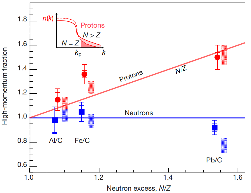
This characteristic of the strong nuclear force has been studied over the past years by the Continuous Electron Beam Accelerator Facility (CEBAF) Large Acceptance Spectrometer (CLAS) collaboration, [3] in high-energy electron scattering experiments, using stable targets. One of their most relevant results indicates that the fraction of high-momentum protons increases with the neutron excess in the nucleus, see figure 1. This could have very strong implications in the description of high-density nuclear matter environments like neutron stars [4]. These high-momentum nucleon pairs are directly connected to the changes observed in the quark distribution in bound nucleons inside nuclei (the so-called EMC effect) [5]
As studies in stable nuclei do not allow to explore these effects at higher N/Z values, it is mandatory to orient the efforts towards exotic nuclear systems. However, reaction targets of radioactive isotopes are not available at N/Z , and thus reaction studies need to be performed in inverse kinematics.
Along this line, a first SRC study using inverse kinematics was carried out in Dubna by the Baryonic Matter @ Nuclotron-based Ion Collider fAcility (NICA) (BM@N) collaboration, [6]. In this experiment, a stable beam of 12C, with an energy of 3.2 AGeV, collided against a proton target, studying the 12C(p,2p)X reaction. By measuring the emitted nucleons in coincidence with the residual nuclei 11B and 10Be, a limited but significant amount of SRC events were observed, paving the path towards experiments with radioactive beams using similar reaction kinematics.
As such, the Reactions with Relativistic Radioactive (R3B) collaboration of the upcoming Facility for Antiproton and Ion Research (FAIR) has designed and constructed an experimental setup. This setup enables the complete characterization of the reaction products from collisions of unstable radioactive beams on a liquid hydrogen target, allowing exclusive measurement of the A(p,2pN)A-2 reaction.
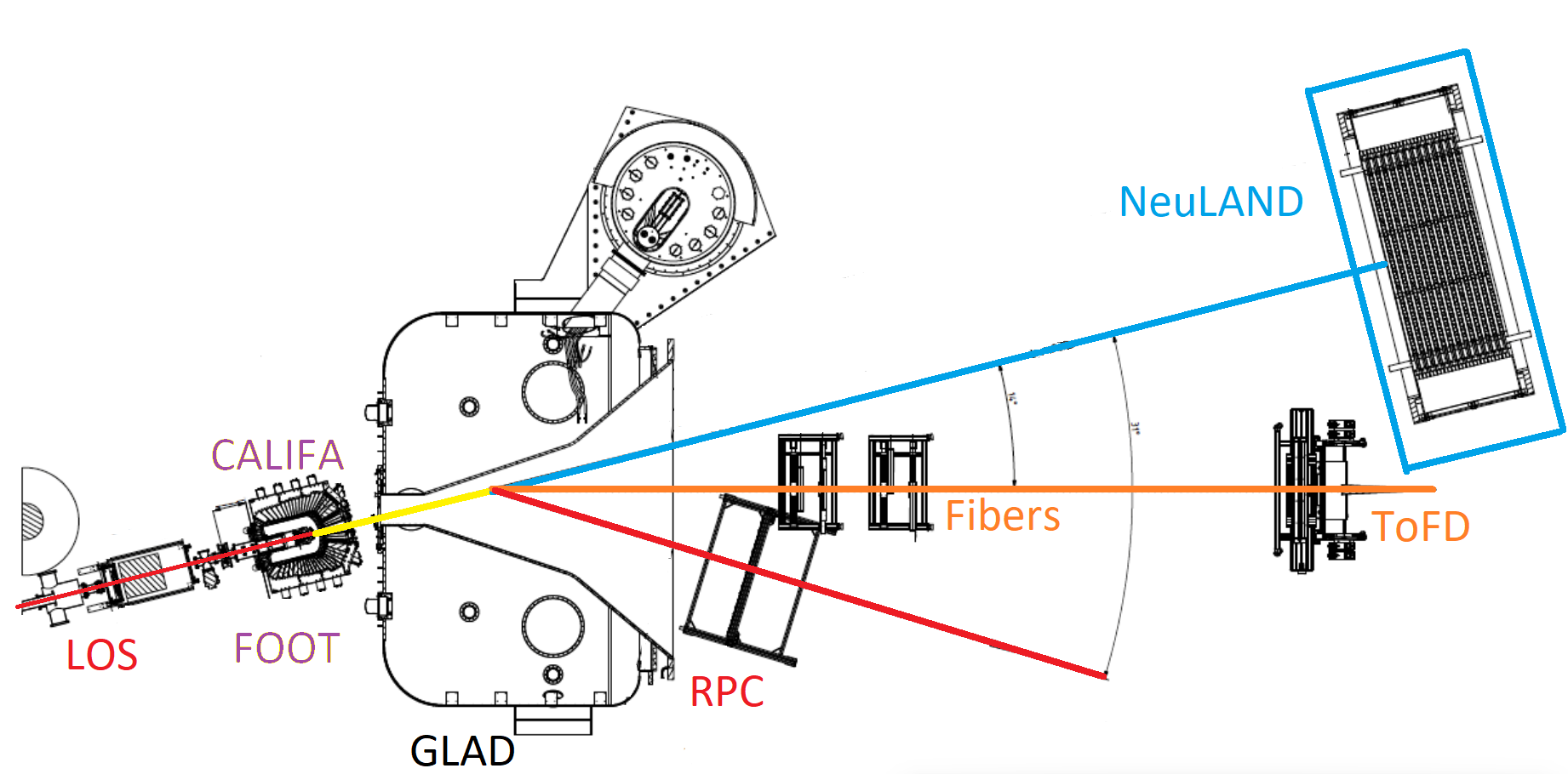
Figure 2 shows the experimental setup designed by the R3B collaboration for this type of measurement, from left to right in the beam direction.
A fast scintillator (LOS) for measuring the start time of the reaction, the CaLorimeter for In-Flight detection of gamma rays and high-energy charged pArticles (CALIFA), a silicon-based detector (FOOT) for reconstructing the reaction vertex, the GSI Large Acceptance Dipole (GLAD), a superconducting magnet, a scintillator fiber tracker (Fibers), and a scintillator (TOFD) for measurement of the outgoing heavy fragment, the new Large-Area Neutron Detector (NeuLAND) for neutron TOF determination, and a Resistive Plate Chamber (RPC) for proton Time-Of-Flight (TOF) detection.
The RPC detector has been the latest to be incorporated the R3B setup with the objective of precisely measuring, by means of the TOF technique, the momentum of the protons emitted in the forward direction.
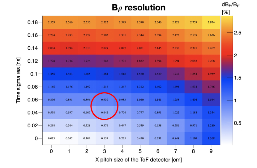
This detector has been previously characterised, achieving a time precision of around ps and a position resolution of approximately cm2 for Minimum Ionising Particles (MIPS) [7]. A study based on simulations shows that such a detector will allow the measurement of the momentum of forward emitted protons with a resolution better than %. This result is shown in figure 3, where the resolution of the rigidity, B, where is the magnetic field of GLAD, the radius of curvature, the proton momentum and the electron charge, is shown as a function of time resolution and pitch size. The RPC detector proposed here, located in the region delimited by the red circle.
This setup was used for the first time to measure SRC in reactions of a 16C radioactive beam, with an energy of AGeV, on a liquid hydrogen target in May 2022. This article concentrates on the characteristics of the RPC detector used, the calibration process, and the first results.
2 The RPC system on the R3B setup
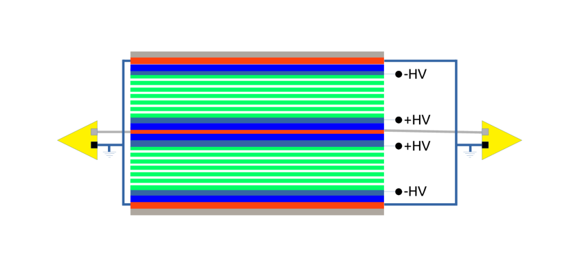
The RPC detector consists of two multigap RPC [8] modules, each of them confined in a permanently sealed plastic111Poly(methyl methacrylate) (PMMA) for the frame and Polycarbonate (PC) for the covers. gas tight box equipped with feed-throughs for gas and High Voltage (HV) connections. Each RPC module has six gas gaps defined by seven mm thick float glass222Bulk resistivity of cm at ∘C electrodes of about mm2 separated by mm nylon mono-filaments. The HV electrodes are made up of a semi-conductive layer333Based on an artistic acrylic paint with around . applied to the outer surface of the outermost glasses with airbrush techniques.
The two modules are read out in parallel by a readout strip plane444Made of mm Flame Retardant 4 (FR4) Printed Circuit Board (PCB). equipped, in one side, with 41 copper strips ( mm width, mm pitch, and mm long) located in between the two modules. Two ground planes, located on top and bottom of the two-module stack, complete the readout planes. The complete structure is enclosed in an aluminum box that provides the necessary electromagnetic insulation and mechanical rigidity. In figure 4 a schematic of the inner structure of the module is shown.
Strips are read from both sides by fast Front End Electronics (FEE) [9]. These are capable of encoding in a single output signal: time (leading edge), with precision ps and charge (pulse width). The charge is obtained by measuring the Time over Threshold () on a copy of the amplified signal, integrated with an integration constant of approximately ns. The resulting signals are read out by TDC-and-Readout Board (TRB)[10], version 3, equipped with multihit Time-to-Digital Converter (TDC) channels (TDC-in-FPGA technology) with a time precision better than ps . This board together with a TRB, version 3sc, integrate an autonomous DAta acQuisition (DAQ) system that exports data and synchronizes, via white rabbit protocol, with the R3B DAQ system.
The RPC was operated in an open gas loop with a mixture of % C2H2F4 and % SF6 at a pressure a few millibars below atmospheric pressure. In this way, the width of the gaps is correctly defined as a result of the compression exerted by the atmospheric pressure. The detector working point was measured to be about kV/gap.
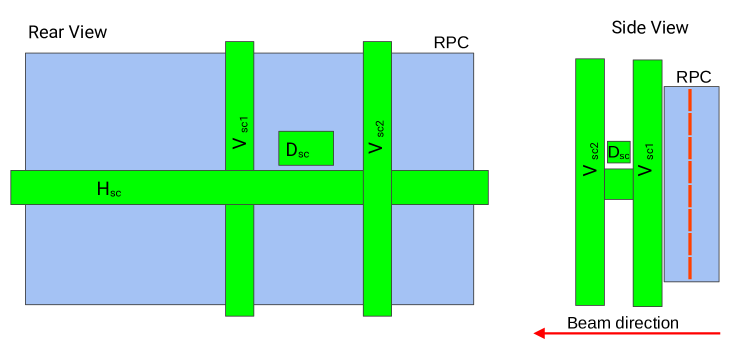
Three scintillation bars [11], two verticals, Vsc1 and Vsc2 and one horizontal, Hsc together with a small, mm long, scintillator, Dsc, were placed behind and parallel to the surface of the RPC, as shown in Figure 5, for calibration purposes. The scintillators are read out on both sides by photomultiplier tubes (PMT), the output signals of which are connected to the same FEE that reads the RPC but without the amplification stage.
For each RPC strip, , with signals on both sides, the measured on the right and left sides, and will be corrected with a calculated offset associated with each of the FEE and TDC involved, and . Computing in this way the charge of each channel,
| (1) |
Furthermore, the strip, , with maximum and , will be the assigned strip of the event and the charge, , can be calculated from and as follows.
| (2) |
Having assigned a strip to the event, the transversal position (across the strips), , can be computed using the number of the strip and the pitch of the strip, ,
| (3) |
For both the time and the longitudinal position (along the strip) , the measured times on the right and left sides of the selected strip will be used, and respectively, being that for each of these variables an offset must be calculated, and .
To calculate the longitudinal position, , equation 4 will be used, where is the propagation velocity of the signals on the strips, mm/ns.
| (4) |
For time the equation 5 will be used.
| (5) |
3 Calibration
The calibration of the RPC was divided into several steps.
3.1 Time over Threshold calibration
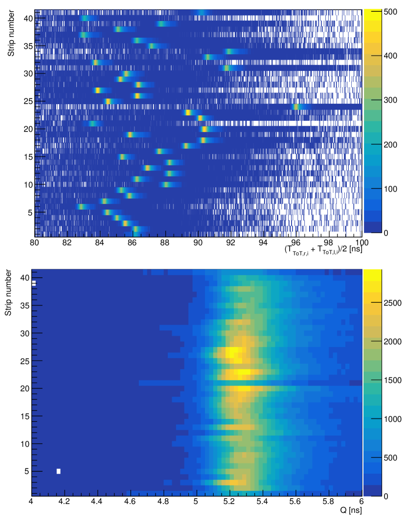
The calibration of the consists in the calculation of the and parameters, originated by the different response of each of the FEE and TDC channels involved, which align the minimum value of and between all channels. This calibration is crucial for the determination of and with the consequent correct calculation of , , and .
If this calibration is not performed correctly, and could be attributed to different channels on the left and right sides, in which case the event would be discarded or attributed to the wrong strip. This is visible in the figure 6 top, where the uncalibrated spectra for each of the strips are plotted. Due to the lack of calibration, % of the events will be discarded. After a correct calibration, figure 6 bottom, the value of events with incorrect decreases to %. More work is being done to further improve this value.
3.2 Longitudinal strip position calibration
After a correct calibration of the and calculation of , the transverse and longitudinal positions, and , are calculated. For the latter, it is necessary to determine the parameters , which have as origin the different time offsets associated with each strip, FEE and TDC channels.
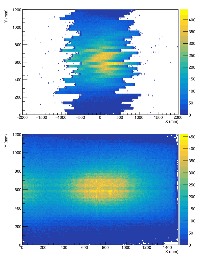
This is visible in the figure 7 top, where a two-dimensional histogram of , , without the calibration parameters, is shown. In contrast, figure 7 bottom shows the same histogram with the calculated calibration parameters, where the central spot corresponding to the forward emitted particles (protons) and the geometrical acceptance defined by the GLAD magnet (halo at the periphery of the plot) are clearly visible.
3.3 Strip time calibration
Finally, the time , can be determined, for which the parameters must be calculated, which have as origin the different time offsets associated with each strip, FEE and TDC channels.
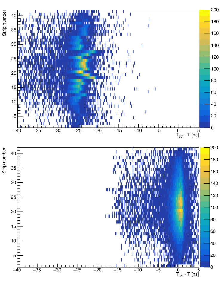
The vertical scintillators are used to calculate these parameters. The differences between the scintillator time and the RPC time, (for the case of the scintillator Vsc1), are calculated for events passing through each of the RPC strips. Assuming that the scintillators are perfectly parallel to the surface of the RPC, the time of flight for the particles between the two detectors should be, on average, equal, without depending on the strip of the RPC that has produced the signal. Therefore, the parameters are calculated such that the average of is always the same.
The result can be seen in figure 8, where , is calculated for each of the strips . In the top part without the calibration parameters and at the bottom with the calculated calibration parameters applied. This procedure ensures that the RPC surface always produces the same time regardless of the strip producing the signal.
4 Beam time performance
The RPC autonomous DAQ system ran without interruption for more than two weeks, delivering data and correctly synchronising with the R3B DAQ.
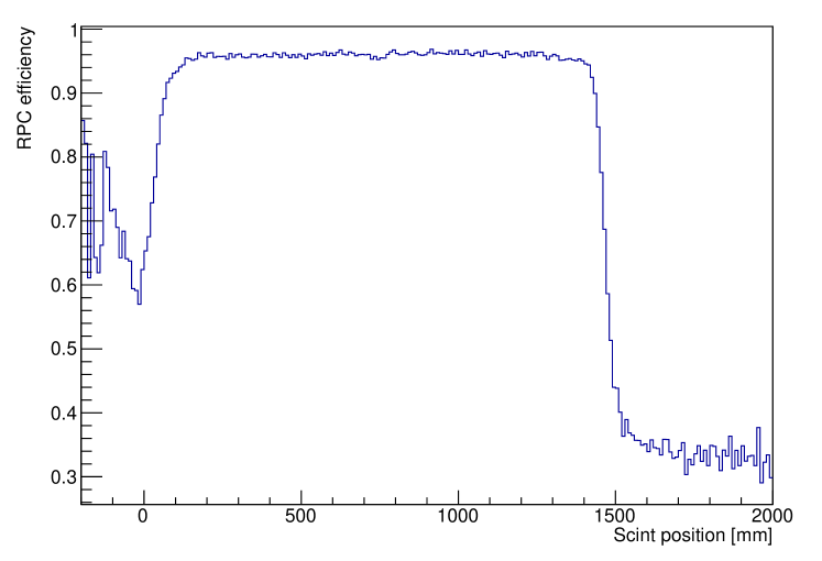
Using the horizontal scintillator, Hsc, the efficiency was calculated on the overlapped area. It was estimated by dividing the events seen by the LOS, RPC and Hsc by all the events seen by the LOS and Hsc detectors. The result can be seen in figure 9 where the efficiency of the RPC is shown as a function of the position given by the scintillator, showing a mean value of %.
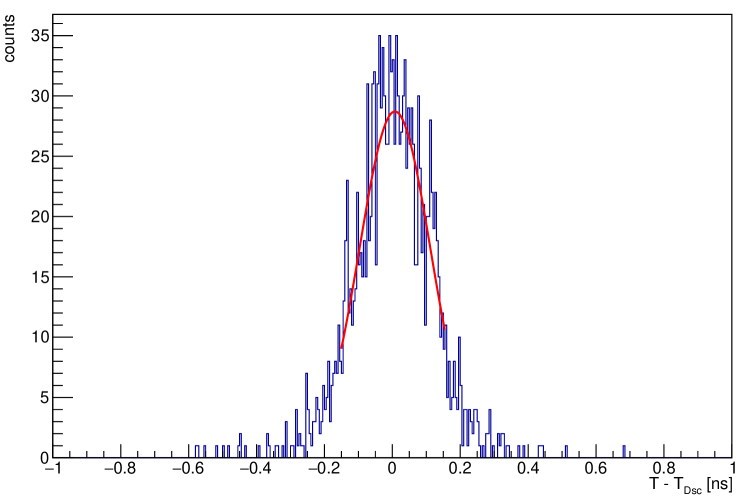
The time precision of the RPC was estimated by performing the time difference between the RPC and the small scintillator (Dsc), which has the best time precision of the four scintillators. Figure 10 shows the time difference , which after fitting the central Gaussian part of the distribution shows a value of ps . This value includes the precision of the RPC, Dsc, and the spread in momentum of the particles. The precision of Dsc was evaluated, in a previous characterization, to be around ps for a collimated monochromatic relativistic pion beam, conditions which are not met here, being its contribution probably higher. The contribution of momentum has been calculated to be negligible for the distance between RPC and Dsc based on the measured TOF between LOS and RPC.
5 Conclusions
The setup (installation, DAQ integration and calibration) of a large area, m2, RPC detector for the precise measurement of the momentum of the forward emitted protons in collisions of unstable radioactive beams on a liquid hydrogen target for the measurement of nucleon-nucleon short-range correlations in the R3B experiment has been successfully done. The RPC exhibits during the first beam time an efficiency higher than % and a time precision better than ps .
6 Acknowledgments
This work was supported by Fundação para a Ciência e Tecnologia (FCT), Portugal, within the framework of the project EXPL/FIS-NUC/0364/2021 and the PhD grant 2021.05736.BD.
References
- [1] J. Carlson et al., ”Quantum Monte Carlo methods for nuclear physics”, Rev. Mod. Phys. 87, 1067 (2015)
- [2] V. V. Burov et al., ”Large momentum pion production in proton nucleus collisions and the idea of “fluctuons” in nuclei”, Phys. Lett. B 67, 46 (1977)
- [3] The CLAS Collaboration, ”Probing high-momentum protons and neutrons in neutron-rich nuclei”, Nature 560, 617–621, (2018).
- [4] L. A. Souza et al., ”Effects of short-range nuclear correlations on the deformability of neutron stars”, Phys. Rev. C 101, 065202 (2020)
- [5] Or. Hen et al., ”Nucleon–nucleon correlations, short-lived excitations, and the quarks within”, Rev. Mod. Phys. 89, 045002, (2017).
- [6] M. Patsyuk et al., ”Unperturbed inverse kinematics nucleon knockout measurements with a carbon beam”, Nature Physics 17.6, 693-699, (2021).
- [7] A. Blanco et al., ”The SHiP timing detector based on MRPC”, Journal of Instrumentation, C10017, (2020).
- [8] E. Cerron Zeballos et al., ”A new type of resistive plate chamber: The multigap RPC”, NIMA, 374, 1, 132 - 135, (1996).
- [9] D. Belver et al., ”Performance of the Low-Jitter High-Gain/Bandwidth Front-End Electronics of the HADES tRPC Wall”, TNS 57(5), 2848-2856, (2010).
- [10] A. Neiser et al., ”TRB3: a 264 channel high precision TDC platform and its applications”, Journal of Instrumentation, 8(12), C12043-C12043, (2013).
- [11] K. Boretzky et al. ”NeuLAND: The high-resolution neutron time-of-flight spectrometer for R3B at FAIR”, NIMA, 1014, 165701, (2021).