The design and performance of the XL-Calibur anticoincidence shield
Abstract
The XL-Calibur balloon-borne hard X-ray polarimetry mission comprises a Compton-scattering polarimeter placed at the focal point of an X-ray mirror. The polarimeter is housed within a BGO anticoincidence shield, which is needed to mitigate the considerable background radiation present at the observation altitude of 40 km. This paper details the design, construction and testing of the anticoincidence shield, as well as the performance measured during the week-long maiden flight from Esrange Space Centre to the Canadian Northwest Territories in July 2022. The in-flight performance of the shield followed design expectations, with a veto threshold 100 keV and a measured background rate of 0.5 Hz (20–40 keV). This is compatible with the scientific goals of the mission, where %-level minimum detectable polarisation is sought for a Hz-level source rate.
keywords:
Anticoincidence , BGO scintillator , Photomultiplier tube , X-ray polarimetry , scientific ballooning , Monte Carlo , qualification testing1 Introduction
1.1 Overview
New information on the innermost regions of black-hole and neutron-star binary systems, as well as the emission locale of isolated pulsars, can be obtained by measuring the linear polarisation of the X-ray emission, characterised through the polarisation fraction (PF, %) and polarisation angle (PA, degrees) [1, 2, 3]. X-ray polarimetry is complementary to the well-established imaging, timing and spectroscopy measurements which have yielded essentially all information on such sources to date.
The XL-Calibur [4] X-ray polarimetry mission operates in the 15–80 keV energy band, which allows Compton reflection from black-hole accretion disks and cyclotron-resonant scattering in magnetised neutron stars to be studied. Observations are conducted from a stabilised balloon-borne platform, at an altitude of 40 km, where the atmospheric absorption is low for 15 keV photons. A 10 arcmin field-of-view mirror focusses X-rays over 12 m onto the polarimeter assembly, as shown in Figure 1. The design of XL-Calibur follows that of X-Calibur, which flew from Antarctica in December 2018 [5, 6]. XL-Calibur features several improvements over X-Calibur, including a larger focal length mirror (12 m instead of 8 m), with a larger effective area; an improved anticoincidence shield; thinner and lower-background solid state Cadmium Zinc Telluride (CZT) detectors; and, lower energy threshold CZT read-out electronics.
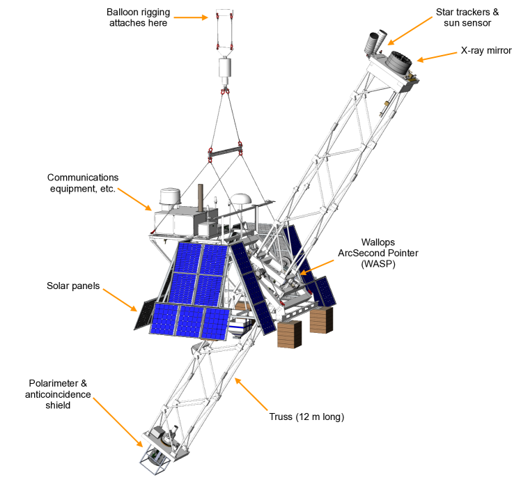
The mirror is mounted at one end of a stiff and lightweight truss, while the polarimeter is mounted at the opposite end. The truss is pointed with arcsecond accuracy by the Wallops Arc Second Pointer (WASP) [7]. The polarimeter comprises an 8 cm long, 1.2 cm diameter, beryllium (Be) rod, which is surrounded by 4 sets of orthogonally circumadjacent CZT detectors, allowing the Compton-scattering angle of photons in an incident X-ray beam to be determined. Photons will preferentially scatter perpendicular to the electric field direction. The amplitude and phase of the resulting azimuthal counting rate modulation encodes the polarisation properties of the beam. The polarimeter continuously rotates about the viewing axis (twice per minute), to mitigate systematic effects arising from any non-uniform instrument response.
Particle and photon radiation present in the stratosphere can generate a signal in the polarimeter, which cannot be distinguished from that caused by X-ray emission from a celestial source, i.e. a single energy deposit (’hit’), above threshold, in one of the CZT detectors. The polarimeter is therefore mounted inside the bore of a several-cm thick Bi4Ge3O12 (BGO) scintillator anticoincidence shield – the focus of this paper. Energy deposits in the shield volume generate a scintillation signal (referred to here as a ’veto’ if above a threshold value) which allows background events to be rejected within a chosen time-window.
XL-Calibur was launched from the Esrange Space Centre, near Kiruna, in northern Sweden on 11th July at 23:45 UTC. The planned observations of the Crab, Cyg X-1 and Her X-1 were disrupted by technical problems during the flight. The performance of the anticoincidence shield was studied in detail, however.
1.2 The X-Calibur shield
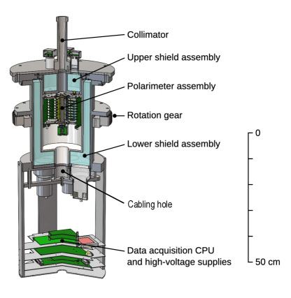
The X-Calibur anticoincidence shield, which flew in 2018, was constructed from CsI(Na) scintillator read out by photomultiplier tubes (PMT), as detailed in Figure 2. The volume of the shield bore needed to accommodate the polarimeter was relatively large since the CZT read-out electronics boards were arranged perpendicular to the CZT detectors. This dictated the overall dimensions of the shield (outer diameter 245 mm). The overall mass was 85 kg including the mechanics, and a 10 kg tungsten plate onto which a tungsten collimator was mounted.
During the 2018 X-Calibur flight, a shield energy threshold of 1 MeV was needed to obtain an acceptable polarimeter dead-time fraction 5% [4, 6]. This was significantly higher than the foreseen threshold of 100 keV. Laboratory tests subsequently demonstrated that the high dead-time was due to minimum-ionising particles (MIPs) passing through the 3 cm thick CsI(Na) shield. The resulting large-amplitude PMT pulses saturated the read-out electronics generating significant shield dead-time (50 s), and consequently degraded the background rejection performance. Suppressing the amplitude of MIP-induced PMT pulses is a key requirement for the XL-Calibur shield.
1.3 The XL-Calibur shield
A reduction in the shield mass was a key goal for XL-Calibur, to offset the higher weight of the longer truss (12 m instead of 8 m), so as not to deteriorate the balloon float altitude. A shield redesign could also take advantage of the new polarimeter design for XL-Calibur, where the CZT read-out system allows a more compact design.
The main design changes for the XL-Calibur shield are:
-
1.
BGO scintillator is used since (a) it has a higher stopping power (7.1 g/cm3 density, compared to 4.5 g/cm3 for CsI(Na)); (b) it has a faster scintillation decay time (0.3 s, compared to 0.5 s (slow component) and 4.2 s (fast component) for CsI(Na)), which reduces the shield dead-time; (c) it is easier to handle, as it is not hygroscopic and is mechanically robust.
-
2.
Changes are made to the PMT voltage-divider circuitry, and the front-end electronics design, to mitigate saturation of the readout by MIP events and thereby achieve a 100 keV threshold in the presence of the high MIP-rate in the stratosphere.
-
3.
Elimination of the large-diameter uninstrumented cabling aperture under the X-Calibur polarimeter (see Figure 2), which degrades the rejection performance for albedo background.
1.4 Measurement background and sensitivity
At an atmospheric overburden of a few g/cm2, primary (p, e, ) and secondary (atmospheric) cosmic-rays (p, , e, n, 111The symbol denotes both X-rays and -rays., ) generate a measurement background. The primary cosmic X-ray background [8] is attenuated by the atmosphere, resulting in flux-levels lower than the atmospheric -rays.
Charged cosmic-rays are minimum ionising and the resulting large energy deposits in the shield (14 MeV per cm of traversed BGO) allow this background to be efficiently vetoed. While the low energy component of the -background is likely to be photo-absorbed by the shield (which may result in a veto signal), the nature of the Compton-scattering process means that the high-energy component will preferentially forward-scatter in the shield and may impinge a CZT detector. The energy deposited in the shield may be less than the veto threshold, thereby producing an irreducible background. Moreover, photons which lie above the polarimetry energy range when interacting in a CZT detector may be reconstructed with significantly lower energy due to the loss of charge during diffusion in the CZT bulk because of hole trapping [6].
Neutrons produced in the atmosphere or in detector materials also contribute significantly to the background rate. Neutrons can traverse the shield without depositing energy and impinge a CZT detector. Simulations have shown the contribution to the polarimeter background rate is comparable to that from -rays [4]. Compared to hard X-ray polarimeters which utilise low atomic number detectors, e.g. plastic scintillator [1], the high effective atomic number of CZT reduces the importance of elastic scattering processes. The production of multiple prompt -rays in a characteristic of processes such as de-excitation of Cd after neutron capture (with a high cross-section 0.4 eV [9]); the decay of isomeric states produced when a neutron interacts with Cd, Zn or Te, or when charged particles interact with Bi or Ge; and inelastic processes such as (n,n′,). These backgrounds are suppressed since the multiple -rays are likely to be detected by the shield. An irreducible background may arise from neutron reactions which produce radioactive isotopes (activation) in material in the vicinity of the shield/polarimeter. Isotopes with long decay times compared to the anticoincidence time-window may yield delayed gamma-rays which cannot be vetoed.
An intrinsic source of high-energy background is the decay of 40K (-radiation (maximum energy 1.33 MeV) and -rays (1.46 MeV)), present in building materials on ground and the PMT glass window.
At rigidities below 1 GV, primary charged cosmic-ray spectra (and consequently also the secondary spectra) depend on the geomagnetic latitude, , at which observations are conducted. The background is therefore lower at Esrange () than at McMurdo () on Antarctica (foreseen for future launches). Background levels also depend on the 11-year solar activity cycle, with the lowest background fluxes present during solar-maximum conditions (predicted to next occur in 2025).
For given background conditions, the measurement sensitivity can be expressed in terms of the Minimum Detectable Polarisation (MDP) [10], where there is a 1% chance of measuring a polarisation fraction which exceeds the MDP for an unpolarised beam. The MDP is defined as
| (1) |
where is the modulation factor (which describes the polarimetric response [1]), () is the source (background) rate in Hz, and is the duration of the source observation in seconds. The signal rate is a few Hz for a 1 Crab source (depends on the source elevation and balloon altitude). Observing the Crab for 6 hours each day during a week-long flight results in %-level MDP if Rb 1 Hz. This MDP is an order-of-magnitude lower than previous missions in the hard X-ray band. The Rb-value for a bare polarimeter is a few hundred Hz. The shield is designed to reduce this background rate by two orders-of-magnitude.
2 Design requirements
Monte Carlo simulations of the stratospheric background have been used to study the impact of the shield design on the polarimeter background rate, . Design choices were constrained by the requirement to reuse electrical and mechanical interfaces from the preceding X-Calibur mission. Table 1 lists the design requirements.
| # | Parameter | Requirement | Remarks |
| I. Scientific requirement | |||
| I-a. | Background rate | 1 Hz | to achieve target MDP (Equation 1). |
| II. Shield detector requirements | |||
| II-a. | Veto threshold | 100 keV | from Monte Carlo simulations (Fig. 4) |
| II-b. | Anticoincidence trigger rate limit | 20 kHz | See §3. |
| II-c. | Light tightness | Required. | Light leaks impair low-energy sensitivity. |
| II-d. | Temperature range | 35 ∘C to 30 ∘C | Due to varying solar illumination during flight. |
| II-e. | Operating pressure | 4–1000 mbar | Prevent high-voltage discharge at low pressure. |
| II-f. | Response calibration | For pre-flight testing only | Should not rely on radioactive sources, since this may not be feasible at all launch sites. |
| II-g. | Response monitoring | For use pre-flight and in-flight | Allow measurement of background rate and shield response. |
| II-h. | Fluorescence line suppression | – | BGO fluorescence emission (28 keV, 30 keV) should not enter the polarimeter. |
| III. Thermo-mechanical requirements | |||
| III-a. | Interface constraints | Compatibility with existing X-Calibur mechanics, including roll bearing | See §4.2. |
| III-b. | Vibration tolerance | Protect BGO crystal and PMTs from damage | Pre-flight transport and parachute landing after flight. |
| III-c. | Focal-point placement | Polarimeter must be located 12 m from mirror | Be rod must lie in the focal plane. |
| III-d. | Thermal management of polarimeter | A thermal path should be provided from the polarimeter so that the operating temperature range is not exceeded | Polarimeter is housed in a copper can and has an electrical power rating of 12 W, with up to 49 W of heating power provided by in-built heaters. |
| III-e. | Mass | The overall mass of the shield assembly should be 85 kg | Mass limit corresponds X-Calibur shield solution |
| IV. Electronics requirements | |||
| IV-a. | Mitigate effect of MIPs | Reduce the 50 s shield dead-time seen for X-Calibur | See §3 and §4.6. |
| IV-b. | Polarimeter dead-time measurement | 1 s accuracy | Measurement of shield-veto induced polarimeter dead-time is required for accurate source flux analysis. |
| IV-c. | Interface constraints | Compatibility with with existing X-Calibur electronics | See §4.6. |
3 Monte Carlo simulations
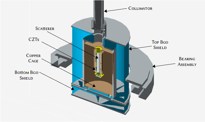
A variety of shield designs were studied using the Geant4 framework [11, 12]. A typical simulation model is shown in Figure 3.
Particles are directed onto a geometric model of the polarimeter housed within the shield. The shield comprises an inverted BGO well seated on a solid disc onto which the polarimeter is mounted. Polarimeter cables exit the assembly radially at the interface between the two shield halves. BGO scintillators are housed in 5 mm thick aluminium enclosures. The polarimeter is represented as a Be rod surrounded by CZT detectors, which are mounted on 3 mm thick copper heat sinks. The polarimeter is mounted in a cylindrical copper Faraday cage with wall thickness 0.8 mm. The model includes high-density items in the vicinity of the polarimeter, such as the tungsten collimator and the gear-wheel/bearing assembly. The bearing attaches to the shield mechanics, allowing the polarimeter to rotate around the viewing axis during observations. The PMTs, CZT front-end electronics, and light-weight aluminium-composite honeycomb panel are not included. Simulations were conducted for a shield/polarimeter elevation of 35∘ (the mean elevation of the Crab viewed from Esrange). Simulations conducted for an elevation of 55∘ gave comparable results, due to the dominantly albedo nature of the background.
The particle background spectra and angular distributions are obtained from MAIRE [13]222https://www.radmod.co.uk/maire and interactions are governed by the Geant4 ’shielding’ physics list333https://www.slac.stanford.edu/comp/physics/geant4/slac_physics_lists/shielding/shielding.html with the inclusion of the Livermore low energy electromagnetic physics list. The step length inside the CZT pixels was reduced to 0.05 mm to account for charge splitting between pixels. The simulated particle flux comprises up- and down-going atmospheric electrons, neutrons and photons, up-going atmospheric protons, and down-going atmospheric and primary protons. The spectra are detailed elsewhere [6]. Simulations assume constant geomagnetic cut-off for the location of Esrange. In MAIRE, solar activity (modulation potential, ) is specified at run-time by selecting an appropriate date. A date from the previous solar cycle was selected, 14th April, 2014, which had the same level of solar activity (sun-spot number) as that measured at the time of the XL-Calibur flight.
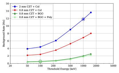
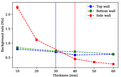
Due to redesigned read-out electronics [4], the XL-Calibur polarimeter occupies a smaller volume than X-Calibur. Consequently, the inner wall of the shield can lie closer to the polarimeter, and the shield volume is smaller. Moreover, XL-Calibur uses thinner CZT detectors (0.8 mm instead of 2 mm), which reduces the background rate by a factor of 2. A variety of shield geometries (e.g. different shield wall thicknesses) were studied. The effect of an additional high density polyethylene layer surrounding the shield (to suppress the background from atmospheric neutrons), and the background dependence on the shield veto threshold and dead-time were also studied. Primary conclusions from these studies are summarised below and illustrated in Figure 4 and Figure 5.
-
1.
Surrounding the polarimeter with 3 cm BGO wall thickness results in a background rate of a few Hz (Fig. 5), while still keeping the overall anticoincidence mass (45 kg) and longest dimension (30 cm) within limits placed by the X-Calibur design. Additional passive absorbing material (such as the tungsten top-plate used in X-Calibur) offered no significant improvement in background rejection performance.
-
2.
Such a BGO shield rejects 99% of the charged particle (electrons and protons) background.
-
3.
High energy (10 MeV) albedo gamma-rays and neutrons are primarily responsible for the background which leaks through the shield without raising a veto signal.
- 4.
-
5.
The shield veto rate reduces from 50 kHz for X-Calibur to 20 kHz for XL-Calibur – see requirement 1 – thereby reducing the polarimeter dead-time.
-
6.
The BGO shield passively reduces the background in the polarimeter from a few hundred Hz to 30 Hz, and actively reduces the background by two orders of magnitude (to give a background-induced rate of 0.5 Hz). A fully efficient active veto is therefore a very important part of the shield design.
-
7.
The addition of a 3 cm thick layer of polyethylene provides a marginal reduction in the neutron background since most of the slow neutrons stopped by the polyethylene are also stopped or flagged by the BGO in (n,) reactions. A thicker polyethylene layer would lead to an unacceptable increase in the payload mass and is not compatible with the current mechanical interface.
4 Shield design
4.1 Overview
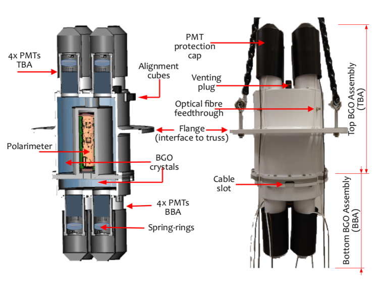
The anticoincidence shield comprises two assemblies, as shown in Figure 6. The polarimeter is mounted on BBA (Bottom BGO Assembly), with the aluminum casing providing a heat path from the polarimeter. The TBA (Top BGO Assembly) is formed as an inverted well, into which the polarimeter is inserted. The overall weight of TBA (BBA) is 45.5 kg (12.0 kg). With the exception of four small slots equispaced around the TBA/BBA interface, the resulting assembly fully surrounds the polarimeter and shields background from all directions. A 20 cm long, 8-10 mm thick tungsten collimator is mounted at the shield aperture to provide a field-of-view comparable to the mirror point-spread function (2′ Half Power Diameter), thereby reducing bore-sight background. The components of the shield are described in the following Sections.
4.2 Mechanical assembly
The shield mechanics (PMT housing) is made from 5 mm (3 mm) thick aluminium alloy 6061. The shield wall thickness prevents Ge Kα,β and Bi Lα,β BGO fluorescence lines [14] from impinging the polarimeter CZT detectors (requirement 1). A flange machined into TBA interfaces to a ring bearing assembly mounted on the aluminium-composite honeycomb panel, which is mounted at the end of the truss. This allows the polarimeter and shield to rotate around the viewing axis during observations. The mechanics wall thickness is dimensioned to maintain the polarimeter alignment with the mirror and to protect components during the shock-levels expected during parachute deployment and landing at the end of the flight. Silicone O-rings are used to prevent light leakage (requirement 1) through joints between mechanical elements. Light-tight vents are mounted on TBA and BBA to ensure that the interior of the shield follows the ambient pressure. Optical fiber feedthroughs (one for each quadrant of TBA and one for BBA) allow LED calibration of the PMT and readout electronics (requirement 1). In order to dampen shocks and vibrations during transport and launch/landing operations, 1-2 mm thick silicone sheets are inserted between the BGO crystal face and the interior wall of the mechanics (requirement 1).
4.3 BGO scintillator
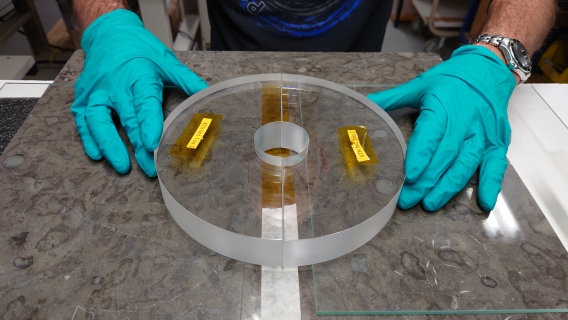
The BGO scintillators were originally procured for the PoGOLite mission [15] from Nikolaev Institute of Inorganic Chemistry444http://niic.nsc.ru/institute/881-niic in 2007. Spare material was returned to NIIC in 2020, melted down, and used to grow the XL-Calibur shield crystals. Due to manufacturing constraints on the crystal boule size, the TBA (BBA) crystal is segmented into 4 (2) pieces, as shown in Figure 7.
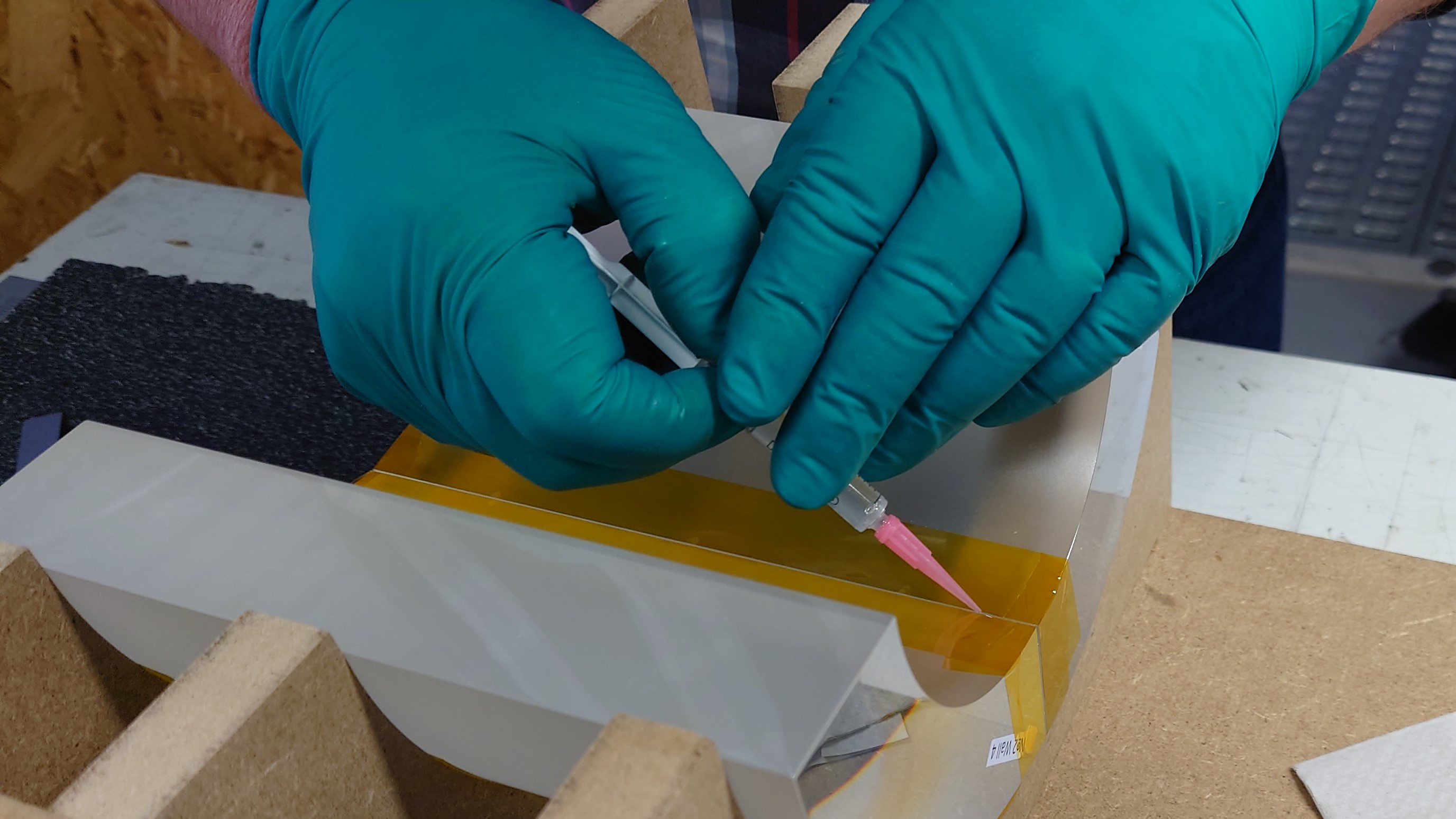
The effect of different crystal surface treatments on light-yield was evaluated by the manufacturer using scaled-down crystals. Flat crystal surfaces are polished to a mirror-like finish and curved surfaces are chemical etched. Each delivered crystal was checked for dimensional conformity, internal defects, and characterised for light-yield uniformity using a flight PMT (Section 4.4) with 241Am (59.5 keV) and 137Cs (662 keV) radioactive sources. The BGO crystals were glued together using Epoxy Technology EPO-TEK 301555https://www.epotek.com/docs/en/Datasheet/301.pdf at Stockholm Polymerteknik AB666https://polymerteknik.com/.
After gluing, the TBA and BBA crystal assemblies were wrapped in double layers of ESR sheets777Enhanced Specular Reflector, manufactured by 3M., which reflect 98% of the scintillation light over a large range of incidence angles.
4.4 Photomultipliers
Both TBA and the BBA are redundantly read out using four Hamamatsu R6231-100-01/001 PMTs, as shown in Figure 6. The devices comprise a glass vacuum tube, which has a window diameter of 51 mm (with a minimum photocathode diameter of 46 mm), and a body length of 77 mm. All PMTs are screened by the manufacturer to have a peak quantum efficiency of at least 38%. The quantum efficiency exceeds 10% in the range 300-550 nm, with a peak at 400 nm, which is reasonably well-matched to the emission of BGO in 370-650 nm, with the peak at 480 nm.
A 1 mm thick Eljen Technology EJ-560 silicone pad and EJ-550 optical grease couple the PMT to the scintillator and protect the thin PMT window from vibrations and shocks. The pads are kept in compression using a phosphor-bronze spring mounted behind the PMT.
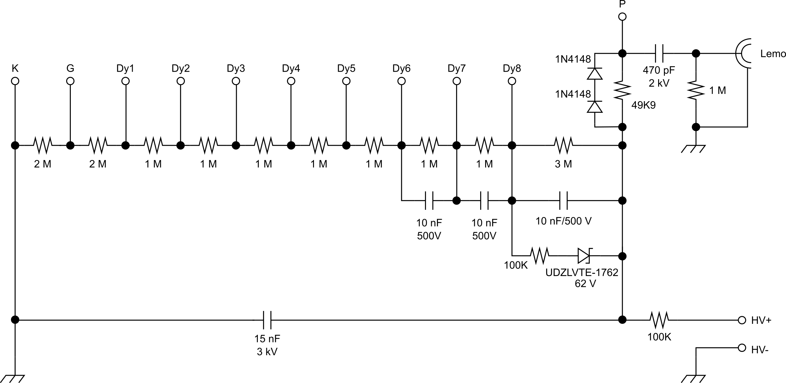
The PMT was biased as shown in Figure 8. At a representative operating voltage of 1400 V, the photomultiplier gain exceeds 106. To limit the shield dead-time resulting from large-amplitude pulses (requirement 1), a Zener-diode clamp is added to the final stage of the dynode chain, following the approach detailed in [16]. The effect of this is demonstrated in Figure 9. Components are mounted on a double-sided custom printed circuit board (PCB) which is soldered onto the PMT leads. Signal connections to the PCB are made using 50 LEMO 00-series connectors. When designing the PCB, care was taken to minimise the electric field gradient between components and/or traces. Teledyne Reynolds 600-series connectors and factory-terminated cable assemblies are used for high-voltage connections. The bias voltage for each PMT is provided by a unique DC/DC unit (HVM Technology UMHV1220), which can provide a maximum 250 A at 2000 V from a 12 V supply.
4.5 Discharge prevention
A common failure mode for balloon missions utilising high-voltage components is electrical discharge in the rarefied atmosphere present at float altitude (3-5 hPa). As described by Paschen’s Law [17], the potential difference required to initiate electrical discharge between two conductors in a gas depends on the conductor separation and pressure. In air at mbar-level pressure, the discharge voltage can be as low as a few 100 V for conductors separated by a few mm. All high-voltage components are therefore encapsulated in a two-component silicone potting compound, Momentive RTV627. The opaque compound has a dielectric strength of 510 V/mil and its low viscosity reduces the risk of forming voids inside the encapsulation. Prior to potting, solder joints were inspected to confirm that no sharp protrusions were present. All surfaces which come into contact with the potting compound were treated with Momentive SS4155 primer compound to improve adhesion. The PMT/HV divider assembly is inserted into a plexiglass tube, with the window-end of the tube sealed against the PMT to allow the remaining tube volume to be filled with potting compound. The mixed potting compound is placed in a degassing chamber at a vacuum of 1 mbar for 2 minutes to expel air bubbles. The mixture is then slowly poured into the PMT assembly with care taken to avoid the formation of voids. Once pouring is completed, the assembly is again placed into the degassing chamber under a vacuum of 1 mbar for 20 minutes. The assembly is then placed in a levelled oven and left to cure at 40∘C for 48 hours. The same procedure was used for potting the high voltage DC/DC converters, which are individually housed in aluminium enclosures mounted on the polarimeter electronics stack.
The potted PMTs are covered in 0.15 mm thick high-permeability magnetic shielding foil (Thorlabs MSFHP) to shield the PMTs from external magnetic fields. The PMT assembly is covered in opaque aluminium tape to prevent ambient light leakage into the PMT tube.
4.6 Data acquisition
The design of the shield data acquisition (DAQ) system is based on that developed for X-Calibur. A block diagram is shown in Figure 10.
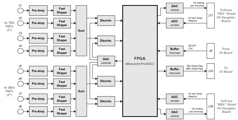
The preamplifier feedback resistor and shaper pole-zero resistor are chosen so that the decay time of the PMT signal fed to the discriminator stage is minimised, without generating a significant undershoot component. When combined with the effect of PMT pulse clamping, the shield dead-time is reduced to a few s (compared to 50 s for X-Calibur), thereby allowing a maximum veto rate of a few hundred kHz (requirement 1 and Section 5.6). To provide more flexibility when setting up the anticoincidence veto, the FPGA logic allows the width and delay of the shield veto pulse to be adjusted, as well as the option to retrigger the veto pulse if a shield discriminator fires while the veto is asserted. Additional FPGA modifications allow the shield performance to be studied during flight. Counters are implemented to measure the discriminator rate, veto signal rate and corresponding veto time (requirements 1, 1 and 1).
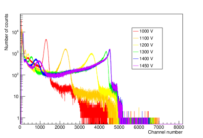
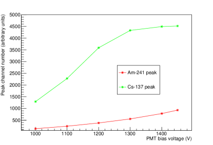
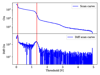
As shown in Figure 10, the summed signal from TBA and BBA is fed to two discriminators. One generates shield veto signals, while the other one is used for a newly-implemented threshold scan. By scanning through the range of threshold settings, a cumulative counts spectrum can be derived. Differentiating the cumulative number of counts bin-by-bin allows an energy spectrum to be reconstructed. During flight, the 8-minute duration scan covers the range 0–5 V, with a step size of 50 mV. Data is collected for 5 s at each step. An example threshold curve with the shield illuminated by radioactive sources on-ground is shown in Figure 11. In flight, the interaction of cosmic-ray, atmospheric, or locally-produced positrons with the payload materials produces a 511 keV annihilation line, which can be used to monitor the shield response.
5 Qualification testing
5.1 Introduction
In order to reduce the risk of in-flight failures due to high-voltage discharge, the PMT assemblies and DC/DC units were subjected to thermal cycling tests at 4 mbar vacuum (requirement 1 and requirement 1). The electronics boards comprising the data acquisition system were tested previously for the X-Calibur mission. The assembled shield was qualified in a thermal cycling chamber at atmospheric pressure. As well as characterising the temperature dependence of the shield response to X-rays, the test also confirms that thermal expansion stresses do not affect the photomultiplier optical coupling or the ambient light seal. A long-term study of the shield response was also conducted with the shield operated in a larger vacuum chamber at room temperature.
5.2 Thermal cycling of high-voltage components in vacuum
Devices under test were placed within a vacuum chamber housed inside a thermal cycling chamber. High-voltage (1450 V) was supplied to the PMTs using a CAEN N472 4-channel power supply, with connections made through the wall of the pressure vessel. The unit provides a current monitor output, which was used to detect discharge events.
The potted PMT assemblies were subjected to two types of thermal cycling test at 4 mbar vacuum. The first test was designed to address possible workmanship issues during fabrication of the PMT assemblies. This ’stress-test’ comprised 5 cycles and lasted for 24 hours, with the temperature profile shown in Figure 12. The fast ramping times are not representative of flight conditions, but were chosen to provoke component failure due to, e.g., differential thermal expansion effects. A single-photoelectron reference spectrum was recorded before and after the test for each PMT. No significant differences were seen between these spectra and no discharge events were registered for any of the PMTs during the cycling. Each PMT assembly was visually inspected at the end of the test. Although the potting compound was sometimes found to partially detach from the plexiglass tube after thermal cycling, the bulk of the potted volume was not affected.
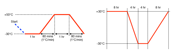
The second thermal cycling test was designed to replicate conditions expected during a balloon flight from Esrange to Canada. Temperature measurements taken during a comparable flight of the PoGO+ mission in summer 2016 [18] were used to define the temperature cycle profile (Figure 12). Temperatures were measured inside the PoGO+ gondola, so that direct solar illumination is avoided – as is the case for the XL-Calibur shield. This test was conducted over 7 cycles of 24 hours, corresponding to the expected flight time. No discharge events were registered during the test. The single-photoelectron spectra measured before and after the test also showed no significant differences.
The potted DC/DC units were tested in a similar manner. In this case, low-voltage control signals were passed into the vacuum chamber, and the high-voltage output was monitored for discharge. After the thermal-cycling ”stress-test”, two of the twelve DC/DC units tested exhibited hairline cracks in the exposed surface of the potting compound. No discharges were registered for these units, but they were rejected for flight as a precautionary measure. Another unit triggered the discharge monitor continuously during the following thermal-cycling ”flight-test” and was similarly rejected. The reason for the failure of this unit could not be determined. All other units passed both thermal-cycling tests. For each functioning unit, the input/output linearity was measured before and after the test. No significant differences were observed.
5.3 Thermal testing of the assembled shield
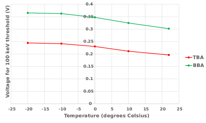
The assembled shield and electronics board were placed in the thermal chamber and threshold scans conducted at 20 ∘C, 10 ∘C, 0 ∘C, +10 ∘C and +25 ∘C with the shield exposed to a 137Cs radioactive source. The light-yield of BGO scintillator is inversely proportional to temperature (-1%/∘C [19]). The position of the 662 keV photopeak was used to calibrate the shield thresholds for a given temperature. Threshold scans were acquired alternately with the shield being operated in darkness and during illumination by strong lighting at each test temperature. No significant differences were observed between these scans, showing that the mechanical structure remained light-tight. The temperature dependence of the 100 keV threshold point is shown in shown in Figure 13.
5.4 Operation of the assembled shield in vacuum
The assembled shield and electronics boards were placed inside a vacuum tank, which was pumped down to 4 mbar. The performance of the shield was periodically monitored during 1 week using threshold scans with the shield was exposed to 241Am and 137Cs radioactive sources. The position of both photopeaks did not change during the test, showing that the shield response was not affected by vacuum conditions.
5.5 Energy threshold calibration and response uniformity
The discriminator threshold is related to deposited energy by irradiating the shield with 137Cs and 241Am sources, while the summing output (Figure 10) is connected to an external preamplifier-shaper-multichannel analyzer set-up. The sources were placed on the symmetry axis of each shield assembly, equidistant from each PMT. Since the PMT gain and PMT-scintillator coupling varies, bias voltages were chosen per PMT to produce the same photopeak position. As a result, the shield response becomes independent of source position.
5.6 Shield trigger rate
Two fibre-coupled 100 mW LEDs (470 nm) are connected through a fibre-splitter, with one LED pulsed to emulate a MIP-like energy deposit, while the other mimics a 100 keV energy deposit (requirement 1). The smallest difference in arrival times at which a 100 keV pulse generates a veto, while riding on the offset baseline of a preceding large-amplitude MIP pulse, was determined to be 2 s, corresponding to background rate of 500 kHz impinging on the shield. This is much larger than the rate of background events expected in flight (requirement 1).
6 Background rejection performance in flight
XL-Calibur was launched from the Esrange Space Centre on July 11th 2022 at 23:45 UTC. The float altitude of 39.6 km was reached at 03:45 UTC the following day. The payload was cut from the balloon on July 18th, and landed by parachute in the Canadian Northern Territories, 500 km Northwest of Yellowknife at 07:40 UTC. The payload suffered little visible damage due to the marshy conditions at the landing site. Hardware is being returned to the laboratory for testing and refurbishment before the next balloon flight.
The shield operated as expected during the flight, with the exception of the following two events: approximately 1.5 hours after launch, at an altitude of 20 km, one of the BBA PMTs was turned off due to an anomalously low high-voltage reading (indicative of discharge); during the early hours of July 15th, one of the TBA PMTs became noisy and was also switched off. The reason for these failures will be determined when hardware is inspected. The effect on shield performance is discussed below.
The shield discriminator rate and dead-time fraction are shown in Figure 14 for the ascent phase and during commissioning at float altitude. The maximum rate of particles detected by the shield (16 kHz) occurs at the Regener-Pfotzer maximum, for a corresponding shield dead-time fraction of 2%. Once float altitude was reached, the shield veto threshold and veto width were adjusted to optimise the shield background rejection performance. A shield threshold of 50 keV was set, without introducing significant dead-time. Increasing the veto width to 3 s (1 s was used during on-ground testing) was found to significantly reduce the 1-hit CZT rate. This is due to the longer BGO scintillation decay time [20] resulting from the lower average shield temperature (see Figure 15) compared to on-ground conditions. The lower temperature also increases the BGO light-yield.
Since each shield scintillator is read out with multiple PMTs, the failure of a single read channel had limited effect. The effective shield energy threshold increases, e.g. the 50 keV threshold set during flight was closer to 70 keV. It is also possible that a position-dependence is introduced to the shield response, but subtracting background measured in off-source pointings would mitigate this.
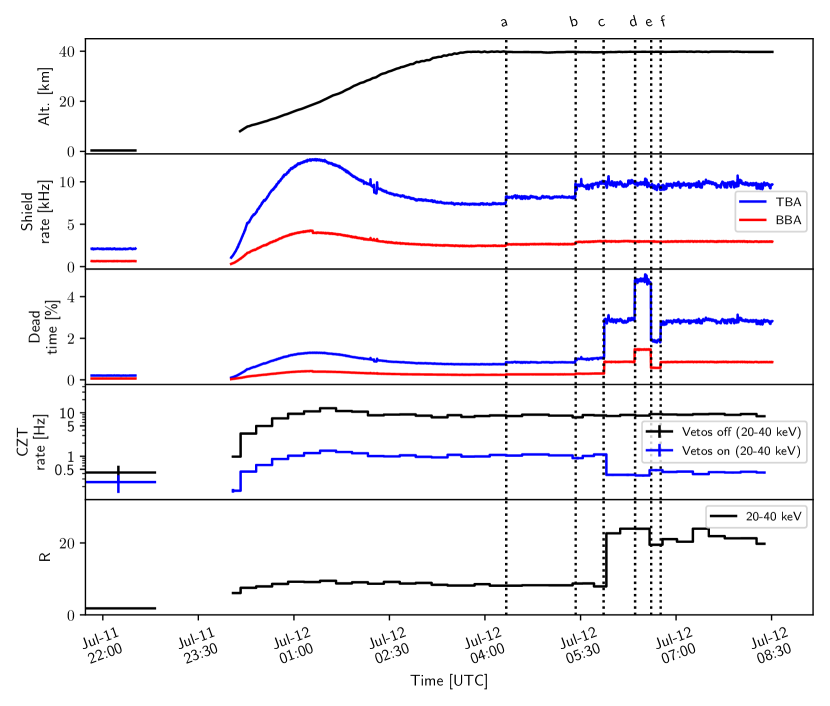
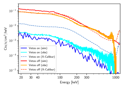
These final settings yielded a shield rate of 12 kHz, for a shield dead-time fraction of 4%. The rate of 1-hit events measured for all CZT detectors (20–40 keV)888This is the energy range with best signal-to-background performance for flight observation conditions. is 8.2 Hz for vetos-off, and 0.5 Hz for vetos-on. The CZT 1-hit rates predicted by the simulation are 10.9 Hz (vetos-off) and 0.16 Hz (vetos-on). In all cases, the error on the measured rate is negligible. Corresponding energy spectra are shown in Figure 16. There is reasonable agreement between data and simulation with vetos-off, indicating that the flux of background particles incident on the shield is well-modelled. The background-rejection efficiency (vetos-on) is over-estimated in the simulation. This is ascribed to simplifications in the Geant4 model, as described in Section 3.
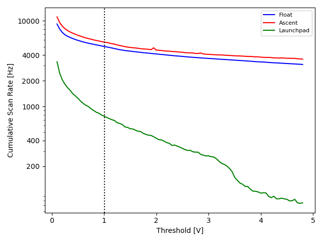
Threshold scans taken on ground, during ascent and at float altitude are shown in Figures 17 and 18. The background on-ground is dominated by relatively low energy interactions compared to float altitude. The active background rejection performance at float altitude is therefore superior to that measured on-ground, as witnessed by the lower panel in Figure 14. The ground spectrum shows a feature at an energy of 1.46 MeV, which is due to gamma-ray decay products of the 40K, as discussed in Section 1.4.
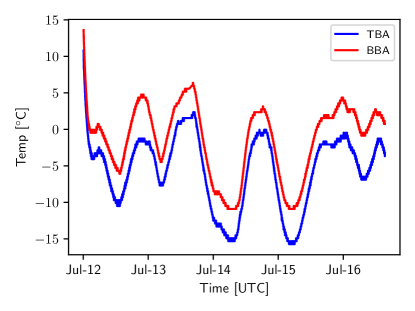
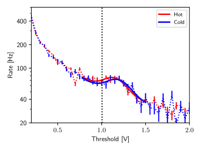
As shown in Figure 15, the shield temperature followed a diurnal pattern during the flight, governed by solar heating999The temperature cycles used during qualification testing (Figure 12) were not well-matched to the measured shield temperature. These flight measurements will inform future qualification tests.. Figure 18 shows threshold scans accumulated during day-time (average temperature 0∘C) and night-time (average temperature (5-10)∘C). The BGO light-yield is consequently higher than during on-ground testing (Figure 13), and the 511 keV peak position moves to a higher apparent energy. The observation of the 511 keV peak demonstrates the potential of monitoring the shield energy scale in-flight, and the effect of variations in the shield temperature.
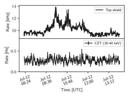
Several times during the flight, the rate of particles incident on the shield was seen to significantly increase temporarily. An example is shown in Figure 19. Such transients were seen on each day of the flight and varied in duration from hours (as shown here) to minutes. The origin of these transient events is interesting, but has not been studied in detail since the effect on the polarimeter 1-hit rate with vetos-on is negligible. Similar transient activity was previously seen in the BGO anticoincidence shield of the PoGOLite and PoGO+ balloon flights from Esrange101010V. Mikhalev, Ph.D. Thesis, KTH Royal Institute of Technology (2018). https://kth.diva-portal.org/smash/record.jsf?pid=diva2%3A1208715..
7 Discussion and outlook
X-ray polarimetry of celestial compact objects in the hard X-ray band is being developed through ballon-borne observations from the stratosphere. The approach is attractive since payloads can be recovered after the flight and modifications can be made based on flight experience. The background environment at the float altitude provided by current balloon technology (40 km) presents a significant challenge when designing instrumentation. The sensitivity of measurements is largely dictated by the efficiency of the background suppression scheme adopted (Equation 1).
The aim of the XL-Calibur mission is to achieve 1%-level MDP, which requires a two orders of magnitude suppression of the polarimeter background rate to 1 Hz. The relatively thick BGO anticoincidence shield newly developed for XL-Calibur has been shown to meet this goal, yielding a 1-hit polarimeter background rate of 0.5 Hz (20–40 keV), measured with shield vetos applied. In Table 2, the cumulative effect of data selections on the polarimeter rate is shown.
| Polarimeter rate (Hz) | ||
| Vetos-off | Vetos- on | |
| All events | 150 | 35 |
| 20-40 keV events | 70 | 5 |
| 1-hit 20-40 keV events | 10 | 0.5 |
The simulation environment used to optimise the shield design uses Geant4 to model the shield geometry and the interactions of particles with spectra defined in the MAIRE radiation environment model (formally known as QARM). This approach has now been validated for both the X-Calibur [6] flight from McMurdo, Antarctica, and the XL-Calibur flight from Esrange. There is good qualitative agreement between measurements and the simulation. Determining the origin of the factor of 2 difference lies outside the scope of this paper, but may be the subject of future work.
The use of high-voltage PMTs allows the BGO scintillation light to be read out with relatively high-efficiency, but introduces the risk of component failure due to high-voltage breakdown processes which may occur in the rarefied atmosphere. Despite lengthy pre-flight qualification tests, where the environment at float was reproduced, components failed during the flight. The redundant read out scheme meant that there was negligible effect on the shield performance, but the situation would have been more precarious if multiple read-out channels had failed for a given scintillator assembly. Post-flight testing will reveal the reason for the failures.
For future flights, scintillator read-out based on robust solid-state photodetectors may be studied. The Hitomi BGO anticoincidence shield was read out using avalanche photodiodes (APD) [21]. The silicon photomultiplier (an array of APDs operated in Geiger mode) is a more recent development with a number of benefits over traditional PMTs, e.g. a low operating voltage (50-100 V) eliminates discharge-related failures, and the device are insensitive to magnetic fields. The quantum efficiency and spectral response are similar to a PMT, and silicon photomultiplier arrays offer comparable light-collection area. The relatively strong temperature dependence of the gain may require more detailed on-ground characterisation and complicate flight operations. An increasing number of missions have adopted these devices, providing valuable experience in their use in the (near-)space environment [22], [23], [24], [25].
Results on source observations are pending the completion of data analysis. Technical issues encountered during the flight may significantly degrade the signal detection efficiency. The full potential of the XL-Calibur design will then be revealed during future flights, from from McMurdo and/or Esrange [4].
Acknowledgements
XL-Calibur is funded by the NASA APRA program under contract number 80NSSC18K0264. KTH authors acknowledge support from the Swedish National Space Agency (grant numbers 199/18 and 2020-00201), and the Swedish Research Council (grant number 2016-04929), which allowed the development and production of the anticoincidence shield. We are indebted to Rolf Helg (KTH) and Bosse Barksäter (KTH) for manufacturing the mechanical parts of the shield during the challenging conditions presented by the pandemic. We also thank Polymerteknik AB for expertly gluing the BGO crystal segments. The majority of the thermal and vacuum test infrastructure used in this work was provided by the KTH Space Centre. Important technical contributions to the project have been made by Dana Braun, Paul Dowkontt, Garry Simburger (Washington University in St. Louis) and Victor Guarino (Guarino Engineering, Illinois). The NASA-CSBF and Esrange teams are thanked for providing balloon launch and operation services. We also thank colleagues from NASA Wallops Flight Facility for operating the WASP pointing system and their support during the balloon campaign.
References
- [1] T. Chattopadhyay, “Hard X-ray polarimetry—an overview of the method, science drivers, and recent findings,” Journal of Astrophysics and Astronomy, vol. 42, no. 2, p. 106, 2021.
- [2] H. Krawczynski, A. Garson, Q. Guo, M. G. Baring, P. Ghosh, M. Beilicke, and K. Lee, “Scientific prospects for hard X-ray polarimetry,” Astroparticle Physics, vol. 34, pp. 550 – 567, 02 2011.
- [3] F. Lei, A. J. Dean, and G. L. Hills, “Compton Polarimetry in Gamma-Ray Astronomy,” Space Science Reviews, vol. 82, pp. 309–388, 00 1997.
- [4] Q. Abarr, H. Awaki, M. Baring, R. Bose, G. D. Geronimo, P. Dowkontt, M. Errando, V. Guarino, K. Hattori, K. Hayashida, F. Imazato, M. Ishida, N. Iyer, F. Kislat, M. Kiss, T. Kitaguchi, H. Krawczynski, L. Lisalda, H. Matake, Y. Maeda, H. Matsumoto, T. Mineta, T. Miyazawa, T. Mizuno, T. Okajima, M. Pearce, B. Rauch, F. Ryde, C. Shreves, S. Spooner, T.-A. Stana, H. Takahashi, M. Takeo, T. Tamagawa, K. Tamura, H. Tsunemi, N. Uchida, Y. Uchida, A. West, E. Wulf, and R. Yamamoto, “XL-Calibur – a second-generation balloon-borne hard X-ray polarimetry mission,” Astroparticle Physics, vol. 126, p. 102529, 2021.
- [5] Q. Abarr, M. Baring, B. Beheshtipour, M. Beilicke, G. d. Geronimo, P. Dowkontt, M. Errando, V. Guarino, N. Iyer, F. Kislat, M. Kiss, T. Kitaguchi, H. Krawczynski, J. Lanzi, S. Li, L. Lisalda, T. Okajima, M. Pearce, L. Press, B. Rauch, D. Stuchlik, H. Takahashi, J. Tang, N. Uchida, A. West, P. Jenke, H. Krimm, A. Lien, C. Malacaria, J. M. Miller, and C. Wilson-Hodge, “Observations of a GX 301–2 Apastron Flare with the X-Calibur Hard X-Ray Polarimeter Supported by NICER , the Swift XRT and BAT, and Fermi GBM,” The Astrophysical Journal, vol. 891, no. 1, p. 70, 2020.
- [6] Q. Abarr, B. Beheshtipour, M. Beilicke, R. Bose, D. Braun, G. d. Geronimo, P. Dowkontt, M. Errando, T. Gadson, V. Guarino, S. Heatwole, M. A. Hossen, N. K. Iyer, F. Kislat, M. Kiss, T. Kitaguchi, H. Krawczynski, R. J. Lanzi, S. Li, L. Lisalda, T. Okajima, M. Pearce, Z. Peterson, L. Press, B. Rauch, G. Simburger, D. Stuchlik, H. Takahashi, J. Tang, N. Uchida, and A. West, “Performance of the X-Calibur Hard X-Ray Polarimetry Mission during its 2018/19 Long-Duration Balloon Flight,” arXiv, 2022.
- [7] D. Stuchlik, “The NASA Wallops Arc-Second Pointer (WASP) System for Precision Pointing of Scientific Balloon Instruments and Telescopes,” AIAA Balloon Systems Conference, 2017.
- [8] M. Ajello, J. Greiner, G. Sato, D. R. Willis, G. Kanbach, A. W. Strong, R. Diehl, G. Hasinger, N. Gehrels, C. B. Markwardt, and J. Tueller, “Cosmic X‐Ray Background and Earth Albedo Spectra with Swift BAT,” The Astrophysical Journal, vol. 689, no. 2, pp. 666–677, 2008.
- [9] P. F. Bloser, J. E. Grindlay, T. Narita, and F. A. Harrison, “CdZnTe background measurement at balloon altitudes with an active BGO shield,” EUV, X-Ray, and Gamma-Ray Instrumentation for Astronomy IX, pp. 186–196, 1998.
- [10] M. C. Weisskopf, R. F. Elsner, and S. L. O’Dell, “On understanding the figures of merit for detection and measurement of x-ray polarization,” vol. 7732 of SPIE Astronomical Telescopes and Instrumentation: Observational Frontiers of Astronomy for the New Decade, pp. 77320E – 77320E–5, SPIE Astronomical Telescopes and Instrumentation: Observational Frontiers of Astronomy for the New Decade, 07 2010.
- [11] J. Allison, K. Amako, J. Apostolakis, P. Arce, M. Asai, T. Aso, E. Bagli, A. Bagulya, S. Banerjee, G. Barrand, B. Beck, A. Bogdanov, D. Brandt, J. Brown, H. Burkhardt, P. Canal, D. Cano-Ott, S. Chauvie, K. Cho, G. Cirrone, G. Cooperman, M. Cortés-Giraldo, G. Cosmo, G. Cuttone, G. Depaola, L. Desorgher, X. Dong, A. Dotti, V. Elvira, G. Folger, Z. Francis, A. Galoyan, L. Garnier, M. Gayer, K. Genser, V. Grichine, S. Guatelli, P. Guèye, P. Gumplinger, A. Howard, I. Hřivnáčová, S. Hwang, S. Incerti, A. Ivanchenko, V. Ivanchenko, F. Jones, S. Jun, P. Kaitaniemi, N. Karakatsanis, M. Karamitrosi, M. Kelsey, A. Kimura, T. Koi, H. Kurashige, A. Lechner, S. Lee, F. Longo, M. Maire, D. Mancusi, A. Mantero, E. Mendoza, B. Morgan, K. Murakami, T. Nikitina, L. Pandola, P. Paprocki, J. Perl, I. Petrović, M. Pia, W. Pokorski, J. Quesada, M. Raine, M. Reis, A. Ribon, A. R. Fira, F. Romano, G. Russo, G. Santin, T. Sasaki, D. Sawkey, J. Shin, I. Strakovsky, A. Taborda, S. Tanaka, B. Tomé, T. Toshito, H. Tran, P. Truscott, L. Urban, V. Uzhinsky, J. Verbeke, M. Verderi, B. Wendt, H. Wenzel, D. Wright, D. Wright, T. Yamashita, J. Yarba, and H. Yoshida, “Recent developments in Geant4,” Nuclear Instruments and Methods in Physics Research Section A: Accelerators, Spectrometers, Detectors and Associated Equipment, vol. 835, pp. 186–225, 2016.
- [12] S. Agostinelli, J. Allison, K. Amako, J. Apostolakis, H. Araujo, P. Arce, M. Asai, D. Axen, S. Banerjee, G. Barrand, F. Behner, L. Bellagamba, J. Boudreau, L. Broglia, A. Brunengo, H. Burkhardt, S. Chauvie, J. Chuma, R. Chytracek, G. Cooperman, G. Cosmo, P. Degtyarenko, A. Dell’Acqua, G. Depaola, D. Dietrich, R. Enami, A. Feliciello, C. Ferguson, H. Fesefeldt, G. Folger, F. Foppiano, A. Forti, S. Garelli, S. Giani, R. Giannitrapani, D. Gibin, J. G. Cadenas, I. González, G. G. Abril, G. Greeniaus, W. Greiner, V. Grichine, A. Grossheim, S. Guatelli, P. Gumplinger, R. Hamatsu, K. Hashimoto, H. Hasui, A. Heikkinen, A. Howard, V. Ivanchenko, A. Johnson, F. Jones, J. Kallenbach, N. Kanaya, M. Kawabata, Y. Kawabata, M. Kawaguti, S. Kelner, P. Kent, A. Kimura, T. Kodama, R. Kokoulin, M. Kossov, H. Kurashige, E. Lamanna, T. Lampén, V. Lara, V. Lefebure, F. Lei, M. Liendl, W. Lockman, F. Longo, S. Magni, M. Maire, E. Medernach, K. Minamimoto, P. M. d. Freitas, Y. Morita, K. Murakami, M. Nagamatu, R. Nartallo, P. Nieminen, T. Nishimura, K. Ohtsubo, M. Okamura, S. O’Neale, Y. Oohata, K. Paech, J. Perl, A. Pfeiffer, M. Pia, F. Ranjard, A. Rybin, S. Sadilov, E. D. Salvo, G. Santin, T. Sasaki, N. Savvas, Y. Sawada, S. Scherer, S. Sei, V. Sirotenko, D. Smith, N. Starkov, H. Stoecker, J. Sulkimo, M. Takahata, S. Tanaka, E. Tcherniaev, E. S. Tehrani, M. Tropeano, P. Truscott, H. Uno, L. Urban, P. Urban, M. Verderi, A. Walkden, W. Wander, H. Weber, J. Wellisch, T. Wenaus, D. Williams, D. Wright, T. Yamada, H. Yoshida, D. Zschiesche, and G. Collaboration, “Geant4—a simulation toolkit,” Nuclear Instruments and Methods in Physics Research Section A: Accelerators, Spectrometers, Detectors and Associated Equipment, vol. 506, no. 3, pp. 250–303, 2003.
- [13] F. Lei, A. Hands, S. Clucas, C. Dyer, and P. Truscott, “Improvement to and Validations of the QinetiQ Atmospheric Radiation Model (QARM),” 2006.
- [14] Y. Furuta, Y. Murota, J. S. Hiraga, M. Sasano, H. Murakami, and K. Nakazawa, “A Study of Active Shielding Optimized for 1-80 keV Wide-Band X-ray Detector in Space,” arXiv, 2015.
- [15] M. Chauvin, H.-G. Florén, M. Jackson, T. Kamae, T. Kawano, M. Kiss, M. Kole, V. Mikhalev, E. Moretti, G. Olofsson, S. Rydström, H. Takahashi, J. Lind, J.-E. Strömberg, O. Welin, A. Iyudin, D. Shifrin, and M. Pearce, “The design and flight performance of the PoGOLite Pathfinder balloon-borne hard X-ray polarimeter,” Experimental Astronomy, vol. 41, no. 1-2, pp. 17–41, 2016.
- [16] C. Tanihata, J. Kataoka, T. Murakami, N. Ota, H. Ozawa, T. Takahashi, T. Tamura, Y. Uchiyama, S. Watanabe, K. Yamaoka, D. Yonetoku, Y. Ezoe, Y. Fukazawa, N. Isobe, N. Iyomoto, T. Kamae, M. Kokubun, J. Kotoku, A. Kubota, K. Makishima, Y. Matsumoto, T. Mizuno, K. Nakazawa, T. Onishi, M. Sugiho, I. Takahashi, M. Tanaka, M. Tashiro, Y. Terada, M. Nomachi, A. Yoshida, M. Hamaya, M. Horii, K. Taguchi, N. Morita, I. Odagi, K. Sato, Y. Tanaka, and K. Mori, “Preflight performance of the ASTRO-E hard-x-ray detector,” EUV, X-Ray, and Gamma-Ray Instrumentation for Astronomy X, pp. 645–663, 1999.
- [17] M. Keidar and I. I. Beilis, “Plasma Engineering,” no. IEEE Trans. Comp. Hybrids Manuf. Technol. 16 1993, pp. 125–155, 2018.
- [18] M. Chauvin, H.-G. Florén, M. Friis, M. Jackson, T. Kamae, J. Kataoka, T. Kawano, M. Kiss, V. Mikhalev, T. Mizuno, N. Ohashi, T. Stana, H. Tajima, H. Takahashi, N. Uchida, and M. Pearce, “Shedding new light on the Crab with polarized X-rays,” Scientific Reports, vol. 7, no. 1, p. 7816, 2017.
- [19] P. Wang, Y. Zhang, Z. Xu, and X. Wang, “Study on the temperature dependence of BGO light yield,” Science China Physics, Mechanics & Astronomy, vol. 57, no. 10, pp. 1898–1901, 2014.
- [20] J. Gironnet, V. Mikhailik, H. Kraus, P. d. Marcillac, and N. Coron, “Scintillation studies of Bi4Ge3O12 (BGO) down to a temperature of 6K,” Nuclear Instruments and Methods in Physics Research Section A: Accelerators, Spectrometers, Detectors and Associated Equipment, vol. 594, no. 3, pp. 358–361, 2008.
- [21] K. Nakazawa, G. Sato, M. Kokubun, T. Enoto, Y. Fukazawa, K. Hagino, K. Hayashi, J. Kataoka, J. Katsuta, S. B. Kobayashi, P. Laurent, F. Lebrun, O. Limousin, D. Maier, K. Makishima, T. Mizuno, K. Mori, T. Nakamori, T. Nakano, H. Noda, H. Odaka, M. Ohno, M. Ohta, S. Saito, R. Sato, H. Tajima, H. Takahashi, T. Takahashi, S. Takeda, T. Tanaka, Y. Terada, H. Uchiyama, Y. Uchiyama, S. Watanabe, K. Yamaoka, Y. Yatsu, and T. Yuasa, “Hard x-ray imager onboard Hitomi (ASTRO-H),” Journal of Astronomical Telescopes, Instruments, and Systems, vol. 4, no. 2, pp. 021410–021410, 2018.
- [22] L. J. Mitchell, B. F. Phlips, R. S. Woolf, T. T. Finne, and W. N. Johnson, “Strontium iodide radiation instrumentation II (SIRI-2),” UV, X-Ray, and Gamma-Ray Space Instrumentation for Astronomy XXI, vol. 11118, pp. 111180I–111180I–18, 2019.
- [23] T. Sharma, P. F. Bloser, J. M. Ryan, J. S. Legere, and M. L. McConnell, “Results from the Advanced Scintillator Compton Telescope (ASCOT) balloon payload,” Space Telescopes and Instrumentation 2020: Ultraviolet to Gamma Ray, vol. 11444, pp. 1144435–1144435–16, 2020.
- [24] R. Kushwah, T. A. Stana, and M. Pearce, “The design and performance of CUBES — a CubeSat X-ray detector,” Journal of Instrumentation, vol. 16, no. 08, p. P08038, 2021.
- [25] Z. H. An, X. L. Sun, D. L. Zhang, S. Yang, X. Q. Li, X. Y. Wen, K. Gong, X. H. Liang, X. J. Liu, Y. Q. Liu, Y. G. Li, S. L. Xiong, Y. B. Xu, F. Zhang, X. Y. Zhao, C. Cai, Z. Chang, G. Chen, C. Chen, Y. Y. Du, P. Y. Feng, M. Gao, R. Gao, D. Y. Guo, J. J. He, D. J. Hou, C. Y. Li, G. Li, L. Li, X. F. Li, M. S. Li, F. J. Lu, H. Lu, B. Meng, W. X. Peng, F. Shi, H. Wang, J. Z. Wang, Y. S. Wang, H. Z. Wang, X. Wen, S. Xiao, Y. P. Xu, J. W. Yang, Q. B. Yi, S. N. Zhang, C. Y. Zhang, C. M. Zhang, F. Zhang, Y. Zhao, and X. Zhou, “The design and performance of GRD onboard the GECAM satellite,” Radiation Detection Technology and Methods, vol. 6, no. 1, pp. 43–52, 2022.