Rheology of Granular Rafts
Abstract
Rheology of macroscopic particle-laden interfaces, called “Granular Rafts” has been experimentally studied, in the simple shear configuration. The shear-stress relation obtained from a classical rheometer exhibits the same behavior as a Bingham fluid and the viscosity diverges with the surface fraction according to evolutions similar to 2D suspensions. The velocity field of the particles that constitute the granular raft has been measured in the stationary state. These measurements reveal non-local rheology similar to dry granular materials. Close to the walls of the rheometer cell, one can observe regions of large local shear rate while in the middle of the cell a quasistatic zone exists. This flowing region, characteristic of granular matter, is described in the framework of an extended kinetic theory showing the evolution of the velocity profile with the imposed shear stress. Measuring the probability density functions of the elementary strains, we provide evidence of a balance between positive and negative elementary strains. This behavior is the signature of a quasistatic region inside the granular raft.
Particle-laden interfaces are ubiquitous in natural environment (e.g. insect colonies Loudet et al. (2005); Mlot et al. (2011)) and industries to build materials with specific properties (e.g. electric or magnetic Forth et al. (2019)), prevent sloshing Moisy et al. (2018) or stabilizing foams or emulsions Pickering (1907); Binks and Murakami (2006). Among their intriguing behavior one can cite their ability to generate armored non spherical or everlasting bubbles Roux et al. (2022) which can support high over or under pressure Bala Subramaniam et al. (2005); Timounay et al. (2017). Their countless applications have generated many studies of their mechanical properties Pitois and Rouyer (2019).
When particles are spread on a liquid surface they deform the interface, interaction forces between them appear. For spheres, the contact angle sets the position of attachment of the liquid/air interface on the particle. For light (small Bond number Vella and Mahadevan (2005)) and large enough particles, gravity and colloïdal interactions are negligible compared to capillaries. The curvature of the interface results from the balance between the particle weight, the Archimedean force and the capillary force which pulls the beads, leading to attractive forces between particles. Under these conditions particle-laden interfaces are often called granular rafts Cicuta and Vella (2009) and their ability to float, to sink or to trap material Protière et al. (2017); Lagarde and Protière (2020) as well as their robustness has been widely studied Petit et al. (2016); Planchette et al. (2018). The behavior of particle-laden interfaces under compression Zang et al. (2010); Jambon-Puillet et al. (2017); Saavedra et al. (2018), or indentation He et al. (2020) is fairly well understood. Their viscoelastic behavior has been studied Zang et al. (2010); Barman and Christopher (2014, 2016), suggesting the importance of local interactions between particles in the macroscopic rheology, however their behavior when submitted to simple shear remains poorly understood.
In 3D, above a yield stress and in the inertial regime, dense granular materials (respectively suspensions) obey to the so-called local friction constitutive law (resp. ), where is the shear stress and the confining pressure, and a dilatancy law (resp. ) where is the packing fraction. and are scalar functions of the inertial number (resp. the viscous number ), with the local shear rate, the particle diameter, their density (and the fluid viscosity) gdrmidi@ polytech. univ-mrs. fr http://www. lmgc.
univ-montp2. fr/MIDI/ (2004); Cassar et al. (2005); Jop et al. (2006); Boyer et al. (2011). This inertial (resp. viscous) number can be seen as the ratio between a characteristic time of strain and a characteristic time of rearrangement (resp. ). However in many cases granular materials exhibit non-local effects which lead to the development of a sheared region next to a quasistatic one. In these situations, granular material rheology deviates from the local constitutive law and several models have been developed to account for this nonlocality Bocquet et al. (2009); Reddy et al. (2011); Bouzid et al. (2013, 2015); Henann and Kamrin (2014); Thomas et al. (2019); Gaume et al. (2020).
To keep the same rheological framework for the description of rafts, we define a microscopic characteristic time related to the rearrangement of the constituting grains. To define , the useful stress scale comes from the surface tension between the liquid and the particles which apply the confining pressure with . Thus one might define this time as and build a capillary inertial number: .
Moreover, due to the capillary forces between the particles, granular rafts may belong to the attractive granular class of materials Lois et al. (2008) with stronger non-local effects, thus different rheology.
In this letter we study the rheology of a granular raft with a classical rheometer with imposed shear stress and address the question of the locality of the particle-laden interfaces behavior. Granular rafts are two-dimensional attractive granular media that exhibit a yield stress function of the particle surface fraction and whose mean behavior can be described as a Bingham fluid. When the raft is sheared, coupling global stress-strain measurements and displacement field measurements reveals that the local capillary inertial number is not homogeneous. While accounting for this behavior using the framework of a continuous hydrodynamic model based on the kinetic theory extended to dense granular systems Losert et al. (2000); Gaume et al. (2020), we highlight that in the region where is smaller than a critical inertial number , the microscopic velocity fluctuations gives rise to a balance between positive and negative elementary strains, thus inhibiting the onset of a macroscopic shear. This is characteristic of a quasistatic regime and suggests a transition to elasticity in nature of the contacts between grains.
Experimental Setup – Granular rafts are obtained by spreading silanized polystyrene spheres (diameter m, wetting contact angle ), setting the mean surface fraction , over a mixture of water and glycerin matching particle density as to avoid sedimentation. Tetradecyl trimethyl ammonium bromide (TTAB) is added to the liquid phase (concentration g.L-1) to reduce the cohesive force between the particles, leading to mN.m-1.
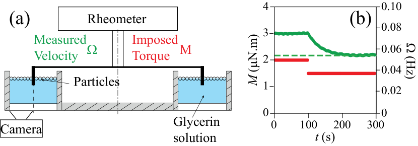
Rafts are sheared in a cylindrical double gap homemade cell of mean radius mm whose two gaps are mm wide (Fig 1a). All the walls are made coarse by gluing at their surfaces the same particles as the ones forming the raft. We place the cell into a MCR 501 rheometer and lower the measuring cylinder mm deep into the solution. The raft is sheared at constant velocity for ten rotations before any measurement. The cylinder is then driven with a constant torque and we allow the system to flow until a steady state is achieved, with a constant rotational speed measured, which comes typically in s (Fig. 1b) and is driven by the fluid flow underneath the raft. Note that the rotational speed corresponds to the cylinder velocity. This steady state can be achieved both with decreasing or increasing torque, showing no hysteresis or long-time variation, and a benchmark measure is performed at the same depth without particles to obtain the resisting torque for the pure fluid at . The expression of the shear stress on the raft, that is the shear stress integrated over its thickness, is then .
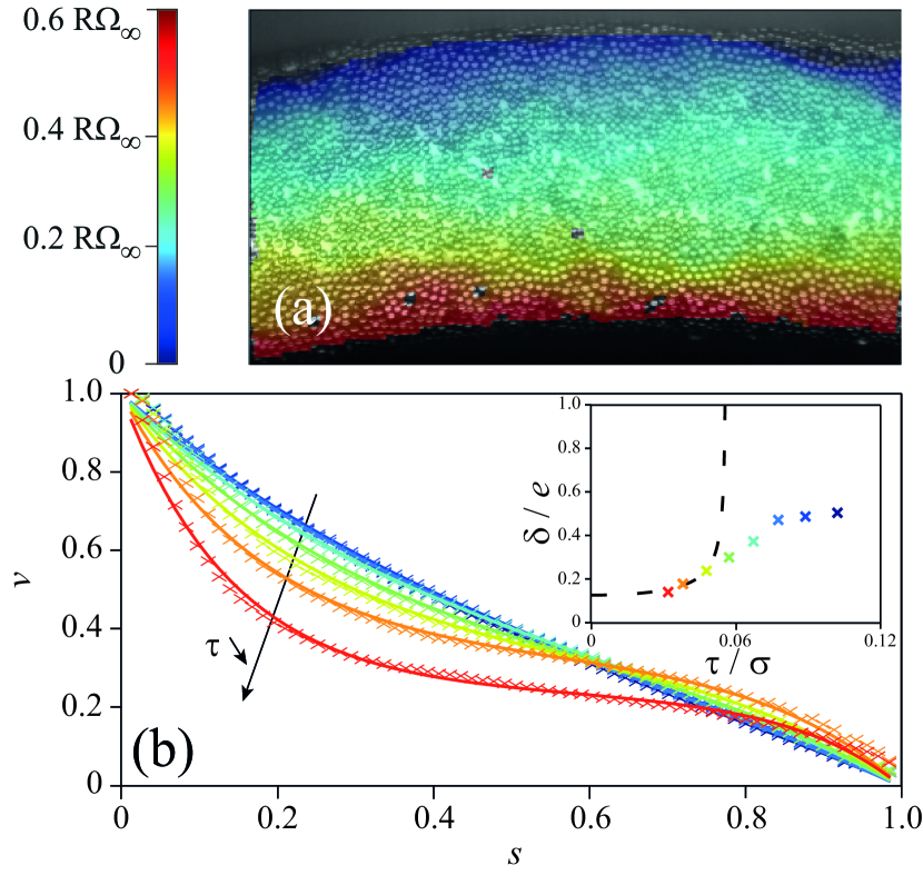
Using a camera set under the raft, the displacement field in the outer gap of the cell is recorded while shearing (Fig. 2a), then processed through image correlation to compute the local time-averaged velocity field. Considering the flow geometry, the results will be presented in polar coordinates centered on the axis of the rheometer in the viewing plane of the camera. Given the range of variation of , we define a reduced space variable . Additionally, the axisymmetry of the system allows to average along the orthoradial direction . Moreover, once in the steady state, we do not observe any displacement along the radial direction. Thus, the instantaneous velocity is . Averaging over time, one obtains the time-averaged velocity . It is then possible to determine the local shear rate . The detection of the grains is feasible in the center of the cell leading to no significant radial variations of in the range , implying no variation in the whole gap.
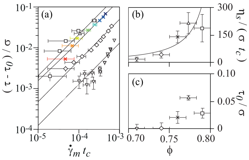
Rheometry – In these experiments performed in a Couette rheometer, it is usual to present the evolution of the mean (surface) stress as a function of the mean shear rate (Fig. 3). The averaged rheological curves show that the rheology of the granular raft follows a Bingham fluid constitutive law Bingham (1922), where is a 2D surface yield stress in Pa.m and is then a 2D surface viscosity thus expressed in Pa.m.s. Figure 3a presents the linear evolution of the normalized stress as a function of the normalized shear rate for different packing fractions . Above a critical particle surface fraction granular rafts exhibit a yield stress which increases with (Fig. 3c). Flowing rafts do so with a constant viscosity, which is a growing function of (Fig. 3b). These findings are in a roughly good agreement with previous studies Reynaert et al. (2007); Zang et al. (2010) and follow the usual rheological law of 2D suspensions Krieger (1972); Brady (1983).
Velocity field – The images taken from a video camera are analyzed by a DIC software (DaVis, LaVision) to get the velocity field of the grains (Fig 2a). From it, we extract azimutal profile . In the observed range, the velocity at which the cylinder rotates is never met by the grains at the wall. To account for this slip velocity, we normalize the velocity by its maximum value leading to . Figure 2b shows the local velocity measurements as a function of distance from the cylinder for decreasing imposed shear stress . Overall, we see that the velocity decreases as the distance to the inner cylinder increases. From this velocity field, we can deduce the local shear rate in our experiments. This decrease of is rather linear when the applied stress is high, leading to a roughly constant shear rate in the raft. But it becomes nonlinear as becomes smaller. We observe a localization of the velocity close to the wall like what can be sometimes observed in dry granular media Losert et al. (2000); Bocquet et al. (2001); Reddy et al. (2011); Seguin et al. (2011). Thus, the local shear rate is not homogeneous in the raft and these velocity field measurements show that the rheology of the rafts is expected to be non-local, different from a Newtonian fluid Guyon et al. (2001), a suspension Blanc et al. (2011) and dry granular medium Reddy et al. (2011).
Hydrodynamic Model – To account for non-locality, the recent rheological models applied to granular flows define a diffusive quantity. Even though the most universal one (in its application) is the non-local granular fluidity (defined as ), a recent review Kamrin (2019) suggests that kinetic theory can be successfully applied while also giving a microscopic physical origin for the velocity fluctuations. Thus, the kinetic theory model is both relevant and sufficient in the case of an homogeneous state of stress.
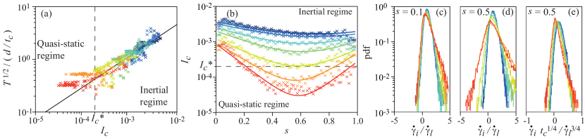
We develop a hydrodynamic model based on the kinetic theory for dry granular media Losert et al. (2000); Bocquet et al. (2001); Seguin et al. (2011); Seguin and Gondret (2017). The classical kinetic theory of molecular systems has been applied with some success to dilute and even dense athermal granular systems by introducing the concept of a "temperature" related to the fluctuations of the time-averaged velocity . Within this framework, heat is created by the flow itself. A moving area increases locally the temperature, thus reducing the resistance to movement of the surrounding particles and allowing them to flow. This effect is then propagated until a steady state is reached. In the present case, the local velocity fluctuations are generated and exchanged in the whole raft through the contacts of the particles in the flow. Assuming pressure and are homogeneous in the whole raft, the effective viscosity varies such as . In the framework of the kinetic theory of granular systems Bocquet et al. (2001), we can define an effective surface viscosity related to the temperature such as where depends on density, diameter, mechanical properties of the particles and pressure, which are constant in the experiment, and is a phenomenological exponent equal to one in dilute and moderately dense systems, and bigger than one in highly dense systems to account for the divergence of the viscosity, e.g. for granular shear flow Losert et al. (2000); Bocquet et al. (2001). The relation between and implies a power-law between the temperature and the local shear-rate . It holds in the inertial regime, that is as long as the contacts by collisions are dominant in the dynamics of the raft; it is then useful to plot the local temperature as a function of the local capillary inertial number (Fig. 4a). For high capillary inertial number, we observe a quasi-linear relationship between the two quantities, with . To latter obtain an analytical solution while introducing no noticeable error, we set leading to , which shows this framework is compatible with the measurements in this flowing regime. For low capillary inertial number, there is another regime where this relationship is no longer valid. It is then possible to define a crossover between these two, characterized by a critical inertial capillary number . Measures of inside the raft (Fig. 4b) show that this criterion is met everywhere for the higher stresses, whereas for lower applied stresses falls under the criterion at a position , which we read from figure 4b and define as the position at which .
Above , the temperature obeys the heat equation in our configuration: equilibrium between diffusion (with a transport coefficient reducing to ), collision dissipation (with a coefficient reducing to ) and source term corresponding to . and depend on density, diameter and mechanical properties of the grains and pressure which are constant in our case. In our geometry, the hydrodynamic equation for comes down to:
| (1) |
which can be integrated to obtain:
| (2) |
where is a characteristic length. Solving equation 2 using and gives:
| (3) |
with A a fitting parameter. This analytical function has been fitted on the velocity profiles showing a excellent agreement with the experimental data (Fig. 1d). Note that the velocity profile so obtained presumes that the whole raft is in an inertial regime. These fits are robust and can be derived in order to extend them to the profiles (Fig. 4b). The diffusion length , found in the analytical solution for , is a growing function of , as observed in figure 4c. Its evolution differs however from the analytical model possibly through the finite size of the experimental system (). Consequently, the stress exceeds the maximal value for an infinite system and estimated at .
Quasistatic Regime – Despite the good agreement between velocity profiles deduced from equation 3 and the experimental data, below the critical inertial capillary number the system is no longer described with the hydrodynamical model. According to a recent numerical study Gaume et al. (2020), for , the system is in a quasistatic regime (similar to a plug flow) in which the strain and thus the velocity fluctuations are sustained by the boundary conditions. In this regime, elementary (local and instantaneous) strains occur over time in and against the forcing. The Probability Density Function of the elementary strains normalized with the local shear rate for two radial locations and are displayed in figures 4c and 4d. For , for any , PDF are narrow and the elementary strains are positive, i.e. in the direction of (Fig. 2b). This is in agreement with a predominance of a viscous component of the stress over an elastic one, as developed in an other numerical study Tighe et al. (2010). At , for the higher imposed torques (), and the PDF are similar. It is no more the case at lower imposed torques, for which : the PDF are large and present negative values (fig 4d); showing important elementary strains opposed to the shear flow, characteristic of the quasistatic regime Gaume et al. (2020). Furthermore, while the velocity profiles cannot show it, the PDF show that in the quasistatic regime, the particles interact through elastic contacts. Indeed, once normalized by , the PDF collapse on a single curve (fig 4e), as proposed in Tighe et al. (2010). This behavior is a signature of the quasistatic regime.
Concluding remarks – The mechanical behavior of granular rafts is close to the one of attractive granular materials. The flow exhibits a non uniform shear, thus revealing two regimes separated by a critical value of the local capillary inertial number . A hydrodynamical model developed from kinetic theory describes well the flow and as predicted by a recent numerical model Gaume et al. (2020), below the critical value the system is in a quasistatic regime. The signature of this quasistatic regime is reflected in the scalings of the probability density function of the elementary strain , as proposed by an other numerical model Tighe et al. (2010). This suggests that the macroscopic transition in the flow regime is in agreement with a microscopic transition in the nature of contacts between the particles. The critical value is found to be one order of magnitude lower than the one predicted for 2D cohesion-free granular materials (), in agreement with numerical study which reported that characteristic relaxation time can be two orders of magnitude lower for attractive granular materials Chaudhuri et al. (2012).
Acknowledgements.
We are grateful to L. Auffray, J. Amarni, A. Aubertin, C. Manquest and R. Pidoux for the development of the experimental setup. The authors thanks N. Retailleau, Y. Khidas, O. Pitois and F. Rouyer for fruitfull discussions. This work is supported by the project PhyGaMa ANR-19-CE30-0009-02 and "Investissements d’Avenir" LabEx Physique: Atomes Lumière Matière (ANR-10-LABX-0039-PALM).References
- Loudet et al. (2005) J. C. Loudet, A. M. Alsayed, J. Zhang, and A. G. Yodh, Phys. Rev. Lett. 94, 018301 (2005).
- Mlot et al. (2011) N. J. Mlot, C. A. Tovey, and D. L. Hu, Proceedings of the National Academy of Sciences 108, 7669 (2011).
- Forth et al. (2019) J. Forth, P. Y. Kim, G. Xie, X. Liu, B. A. Helms, and T. P. Russell, Advanced Materials 31, 1806370 (2019).
- Moisy et al. (2018) F. Moisy, J. Bouvard, and W. Herreman, EPL (Europhysics Letters) 122, 34002 (2018).
- Pickering (1907) S. U. Pickering, J. Chem. Soc., Trans 91, 2001 (1907).
- Binks and Murakami (2006) B. P. Binks and R. Murakami, Nature materials 5, 865 (2006).
- Roux et al. (2022) A. Roux, A. Duchesne, and M. Baudoin, Phys. Rev. Fluids 7, L011601 (2022).
- Bala Subramaniam et al. (2005) A. Bala Subramaniam, M. Abkarian, L. Mahadevan, and H. A. Stone, Nature 438, 930 (2005).
- Timounay et al. (2017) Y. Timounay, O. Pitois, and F. Rouyer, Physical Review Letters 118, 228001 (2017).
- Pitois and Rouyer (2019) O. Pitois and F. Rouyer, Current Opinion in Colloid & Interface Science 43, 125 (2019).
- Vella and Mahadevan (2005) D. Vella and L. Mahadevan, American journal of physics 73, 817 (2005).
- Cicuta and Vella (2009) P. Cicuta and D. Vella, Physical review letters 102, 138302 (2009).
- Protière et al. (2017) S. Protière, C. Josserand, J. M. Aristoff, H. A. Stone, and M. Abkarian, Physical review letters 118, 108001 (2017).
- Lagarde and Protière (2020) A. Lagarde and S. Protière, Phys. Rev. Fluids 5, 044003 (2020).
- Petit et al. (2016) P. Petit, A.-L. Biance, E. Lorenceau, and C. Planchette, Physical Review E 93, 042802 (2016).
- Planchette et al. (2018) C. Planchette, E. Lorenceau, and A.-L. Biance, Soft Matter 14, 6419 (2018).
- Zang et al. (2010) D. Zang, E. Rio, D. Langevin, B. Wei, and B. Binks, The European Physical Journal E 31, 125 (2010).
- Jambon-Puillet et al. (2017) E. Jambon-Puillet, C. Josserand, and S. Protiere, Physical Review Materials 1, 042601 (2017).
- Saavedra et al. (2018) O. Saavedra, H. Elettro, and F. Melo, Physical Review Materials 2, 043603 (2018).
- He et al. (2020) W. He, Y. Sun, and A. D. Dinsmore, Soft Matter 16, 2497 (2020).
- Barman and Christopher (2014) S. Barman and G. F. Christopher, Langmuir 30, 9752 (2014).
- Barman and Christopher (2016) S. Barman and G. F. Christopher, Journal of Rheology 60, 35 (2016).
- gdrmidi@ polytech. univ-mrs. fr http://www. lmgc. univ-montp2. fr/MIDI/ (2004) G. M. gdrmidi@ polytech. univ-mrs. fr http://www. lmgc. univ-montp2. fr/MIDI/, The European Physical Journal E 14, 341 (2004).
- Cassar et al. (2005) C. Cassar, M. Nicolas, and O. Pouliquen, Physics of fluids 17, 103301 (2005).
- Jop et al. (2006) P. Jop, Y. Forterre, and O. Pouliquen, Nature 441, 727 (2006).
- Boyer et al. (2011) F. Boyer, É. Guazzelli, and O. Pouliquen, Physical review letters 107, 188301 (2011).
- Bocquet et al. (2009) L. Bocquet, A. Colin, and A. Ajdari, Physical review letters 103, 036001 (2009).
- Reddy et al. (2011) K. Reddy, Y. Forterre, and O. Pouliquen, Physical Review Letters 106, 108301 (2011).
- Bouzid et al. (2013) M. Bouzid, M. Trulsson, P. Claudin, E. Clément, and B. Andréotti, Phys. Rev. Lett. 111, 238301 (2013).
- Bouzid et al. (2015) M. Bouzid, A. Izzet, M. Trulsson, E. Clément, P. Claudin, and B. Andreotti, Eur. Phys. J. E 38, 125 (2015).
- Henann and Kamrin (2014) D. L. Henann and K. Kamrin, Phys. Rev. Lett. 113, 178001 (2014).
- Thomas et al. (2019) A. Thomas, Z. Tang, K. E. Daniels, and N. Vriend, Soft Matter 15, 8532 (2019).
- Gaume et al. (2020) J. Gaume, G. Chambon, and M. Naaim, Physical Review Letters 125, 188001 (2020).
- Lois et al. (2008) G. Lois, J. Blawzdziewicz, and C. S. O’Hern, Phys. Rev. Lett. 100, 028001 (2008).
- Losert et al. (2000) W. Losert, L. Bocquet, T. C. Lubensky, and J. P. Gollub, Phys. Rev. Lett. 85, 1428 (2000).
- Krieger (1972) I. Krieger, Adv. Colloids Interface Sci. (1972).
- Brady (1983) J. F. Brady, International Journal of Multiphase Flow 10, 113 (1983).
- Bingham (1922) E. C. Bingham, Fluidity and plasticity, Vol. 2 (McGraw-Hill, 1922).
- Reynaert et al. (2007) S. Reynaert, P. Moldenaers, and J. Vermant, Physical Chemistry Chemical Physics 9, 6463 (2007).
- Bocquet et al. (2001) L. Bocquet, W. Losert, D. Schalk, T. C. Lubensky, and J. P. Gollub, Phys. Rev. E 65, 011307 (2001).
- Seguin et al. (2011) A. Seguin, Y. Bertho, P. Gondret, and J. Crassous, Phys. Rev. Lett. 107, 048001 (2011).
- Guyon et al. (2001) E. Guyon, J.-P. Hulin, L. Petit, C. D. Mitescu, et al., Physical hydrodynamics (Oxford university press, 2001).
- Blanc et al. (2011) F. Blanc, F. Peters, and E. Lemaire, Applied Rheology 21 (2011).
- Kamrin (2019) K. Kamrin, Frontiers in Physics 7, 116 (2019).
- Seguin and Gondret (2017) A. Seguin and P. Gondret, Physical Review E 96, 032905 (2017).
- Tighe et al. (2010) B. P. Tighe, E. Woldhuis, J. J. Remmers, W. van Saarloos, and M. van Hecke, Physical review letters 105, 088303 (2010).
- Chaudhuri et al. (2012) P. Chaudhuri, L. Berthier, and L. Bocquet, Phys. Rev. E 85, 021503 (2012).