Emergence of Rashba-/Dresselhaus Effects in Ruddlesden-Popper Halide Perovskites with Octahedral Rotations
Abstract
Ruddelsden-Popper halide perovskites are highly versatile quasi-two-dimensional energy materials with a wide range of tunable optoelectronic properties. Here we use the all-inorganic Csn+1PbnX3n+1 Ruddelsden-Popper perovskites with X=I, Br, and Cl to systematically model the effect of octahedral tilting distortions on the energy landscape, band gaps, macroscopic polarization, and the emergence of Rashba-/Dresselhaus splitting in these materials. We construct all unique and structures following from octahedral tilts and use first-principles density functional theory to calculate total energies, polarizations and band structures, backed up by band gap calculations using the approach. Our results provide design rules for tailoring structural distortions and band-structure properties in all-inorganic Ruddelsden-Popper perovskites through the interplay of the amplitude, direction, and chemical character of the antiferrodistortive distortion modes contributing to each octahedral tilt pattern. Our work emphasizes that, in contrast to 3D perovskites, polar structures may arise from a combination of octahedral tilts, and Rashba-/Dresselhaus splitting in this class of materials is determined by the direction and Pb-I orbital contribution of the polar distortion mode.
1 Introduction
Ruddlesden-Popper (RP) halide perovskites are heterogeneous, layered materials with exceptional photophysical properties due to their quasi-two-dimensional (2D) structures [1, 2, 3, 4, 5, 6, 7, 8, 9]. This family of materials with chemical formula An-1A’2BnX3n+1 can be thought of as derived from the 3D ABX3 perovskites, where A and A’ are monovalent (organic) cations, B is a divalent metal cation (e.g. Pb), X is a halogen anion, and refers to the number of perovskite layers. Even more so than their 3D congeners, RP perovskites feature an enormous structural versatility and can be synthesized in bulk form [1, 2, 6, 10, 11, 12, 13], exfoliated as a monolayer [14], and assembled in interfaces or heterostructures with other layered materials [15, 16]. They owe this flexibility and their robust stability under ambient conditions in a large part to the wide range of organic A and A’ site cations which have been shown to significantly affect the photophysical and thermal properties of this class of materials due to structural and dielectric effects [17, 18, 19, 20, 21, 22, 23, 24].
A particularly intriguing feature of RP perovskites is that their quasi-2D structure, in which the corner-sharing connectivity of the BX6 octahedra is severed in the stacking direction, can lead to a rich landscape of octahedral tilting distortions [25]. In 3D metal-halide perovskites, octahedral tilting is the primary energy-lowering structural distortion. It is well-understood that octahedral tilting in 3D metal-halide perovskites leads to a blueshift of the band gap due to the antibonding nature of the valence band maximum (VBM) and conduction band minimum (CBM) [26]. However, octahedral tilting in 3D perovskites cannot lead to non-centrosymmetric structures; these distortions preserve a global centrosymmetric space group. 3D perovskites with polar space groups exhibiting properties like a macroscopic polarization, ferroelectriciy, or Rashba-/Dresselhaus splitting are therefore rare [27]. This is different in RP perovskites. In RP oxides, octahedral tilting distortions have been explored in depths and led to the development of the concept of hybrid improper ferroelectricity [28] followed by a multitude of predictions of ferroelectric oxides [29, 30]. In RP halide perovskites, the energy landscape of octahedral distortions and their effects on the electronic structure properties has not been systematically studied yet.
Halide perovskites have garnered attention due to their potential for spin-dependent physics that arises as a consequence of strong spin-orbit coupling due to the presence of heavy B site metals like Pb [31, 32]. In combination with noncentrosymmetric structures, spin-orbit coupling leads to the Rashba-/Dresselhaus effect, a lifting of the degeneracy of the energy bands in reciprocal space [33, 34]. This effect can be used for spin-orbitronics, spin-dependent exciton physics, and circular dichroism [35, 36, 37, 21] and is tunable through chemical substitution, electric fields and epitaxial strain [38]. It has also been speculated to contribute to the long carrier recombination times observed in 3D halide perovskites [39], although the experimental evidence for a Rashba-/Dresselhaus effect in 3D halide perovskites is debated due to the lack of a global noncentrosymmetric structure of these materials [40, 41, 42].
A recent study by Jana et al., combining first-principles calculations and experimental structural characterization unraveled design rules for Rashba-/Dresselhaus splitting in hybrid organic-inorganic 2D halide perovskites [43]. These authors showed that some quasi-2D hybrid perovskites do not exhibit Rashba-/Dresselhaus splitting, despite their globally noncentrosymmetric space groups. Instead, Jana et al. correlated the magnitude of the splitting in reciprocal space to an asymmetry in the interoctahedral tilting angles in the inorganic monolayer. For the case of all-inorganic RP perovskites Csn+1PbnI3n+1 with , Maurer et al. showed that only certain types of polar distortions lead to significant Rashba-/Dresselhaus splitting in the CBM [44]. While this systematic study clarified that Rashba-/Dresselhaus splitting is non-negligible in RP perovskites with polar distortions comprising diagonal Pb displacements towards the in-plane edges of the PbI6 octahedron, the effect of the energetically more favorable octahedral tilting distortions on Rashba-/Dresselhaus splitting in RP perovskites was not studied.
Here we use first-principles density functional theory (DFT) to systematically study octahedral tilting distortions in all-inorganic Pb-based RP perovskites. We construct all possible octahedral tilting distortions in Csn+1PbnX3n+1 (X=I, Br, Cl) with and layers and determine their effect on the complex energy landscape of these materials, elucidating energetically favorable distortion modes. We then determine how octahedral tilting modify the band gap of these systems, considering both the size of the gap as well as the emergence of Rashba-/Dresselhaus splitting. Our results, supported by many-body perturbation theory calculations, show which distortion modes have the most significant effects on the band gap. Unlike the case of 3D halide perovskites, not all types of octahedral tilts and rotations open the band gap; the contribution of Pb and X site distortions to the total distortion amplitude is shown to be decisive for predicting the effect of specific distortion modes on the band gap. Furthermore, we show that out of a total of 24 polar structures within and , only four exhibit a pronounced Rashba-/Dresselhaus splitting. In particular, the ground state of is polar, but has negligible Rashba-/Dresselhaus splitting because the polar distortion modes are dominated by an alternating displacement of the Cs ions which do not contribute electronically to the band edges. Finally, to isolate the effect of interlayer stacking in RP halide perovskites, we briefly discuss results for model 2D systems consisting of free-standing halide perovskite mono- and bilayers, respectively. We find that the energy landscape and available band gap ranges are similar to the RP perovskites. However, the lack of interlayer stacking leads to a much smaller number of possible space groups and a reduced number of polar space groups for the monolayer.
We start our discussion with a description of our methods and nomenclature for all RP halide perovskite structures with and in Section 2. In Sections 3 and 4 we discuss the energy landscape and range of band gaps accessible via octahedral tilting distortions. For clarity we focus on materials with X=I and provide complete results for X=Br and X=Cl in the Appendices. We then focus on RP halide perovskites with non-centrosymmetric space groups and their macroscopic electronic polarization and Rashba-/Dresselhaus splitting in Section 5. Section 6 is dedicated to a discussion of 2D mono- and bilayer halide perovskites and the energy landscape and electronic structure of these model systems. The final Section 7 summarizes our conclusions.
2 Methods
2.1 Computational Methods
First-principles DFT calculations were performed using the Vienna Ab initio Simulation Package (VASP) [45, 46]. We used a cutoff energy of 500 eV for the expansion of Kohn-Sham orbitals in the plane wave basis, and projector augmented-wave pseudo-potentials [47] with the following electronic configurations: Cs (), Pb (), I (), Br (), and Cl ().. The exchange-correlation functional of Perdew, Burke, and Ernzerhofer (PBE) [48] was used for all calculations, and spin-orbit-coupling (SOC) was included in the band structure calculations of Section 5. PBE is known to overestimate lattice volumes ( 4%) and underestimate band gaps in halide perovskites. Since these are systematic errors and we are primarily interested in the trends of how octahedral tilting distortions affect the energy landscape, we performed all total energy calculations with the PBE functional and symmetry adapted -point grids using a mesh for cubic CsPbI3 as reference. All structural relaxations were performed until forces were smaller than 0.001 eV/Å. Symmetry mode analysis is performed with isodistort [49]. Macroscopic polarization is computed within the modern theory of polarization. Phonon dispersions are obtained within the harmonic approximation using the Phonopy code [50]. Additionally, we performed band gap calculations for selected cases using Green’s function-based many-body perturbation theory in the ”one-shot” approximation to corroborate the trends we found using DFT-PBE and with SOC included self-consistently. The calculations are performed with the BerkeleyGW [54] code. The zeroth-order one-particle Green’s function and the screened Coulomb interaction are obtained from PBE eigenfunctions and eigenvalues calculated with the Quantum Espresso [51, 52] software package. These DFT-PBE calculations use a plane-wave cutoff energy of 60 Ry, and norm-conserving fully-relativistic pseudopotentials [53]. calculations use a polarizability cutoff of 8 Ry, 1200 bands and a half-shifted -point grid consisting of and points for structures with and symmetry, respectively.
2.2 Structural Notation
The all-inorganic RP structure with formula An+1BnX3n+1, shown in Figure 1(a) can be described as a series of alternating ABX3 perovskite and AX rock-salt layers. The rock-salt layer breaks the connectivity of the BX6 octahedra in -direction (defined as the out-of-plane direction [001]), creating two quasi-2D perovskite slabs A and B, which are shifted by (, , 0) in the -plane against each other ( is the in-plane lattice parameter). The number of layers per slab is denoted by . The undistorted reference structures for and with space group are shown in Figure 1(a). Starting from the reference structures for and , we constructed unique space groups arising from all possible octahedral tilt patterns. The magnitude of the initial tilting angles in the input structures for geometry optimization was set to 6°.
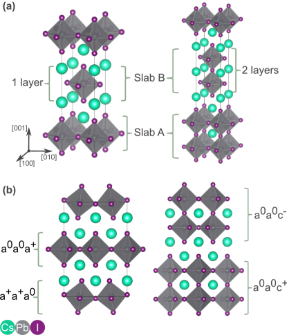
To classify the octahedral tilt pattern of this perovskite family, we adapted the Glazer notation to account for the additional degrees of freedom that arise due to the broken octahedral connectivity in -direction as shown in Figure 1(b). Our notation consists of two tilt patterns, e.g. , corresponding to the tilt patterns of slab A and slab B, respectively. Note that for RP perovskites, one cannot distinguish between in- and out-of-phase rotation along the -direction, as each slab consists of only one perovskite layer. In this case, we use the ”” sign to indicate the presence of a rotation along . Finally, due to the separation of the slabs, there is no unique definition for the direction of rotation of adjacent octahedra of different slabs [55]. We therefore used three additional values , denoting the relative rotation of octahedra in slabs A and B around the three cartesian axes, where stands for in-phase and for out-of-phase rotations (see Figure 1b).
Applying all different combinations of tilt patterns and the different relative rotations of slab A and B to the undistorted structure leads to 38 and 55 unique space groups for and , respectively. From these, 9 structures of and 15 structures of are polar. Additionally, for both and we include structures with pure lead displacements: , and , where the Pb ions are displaced along the in-plane out-of-bond , in-plane in-bond and out-of-plane direction, respectively. The lists of all space groups for and are provided in Tables 1 and 2, respectively (polar space groups are highlighted in green). Corresponding tables for the and bromides and chlorides are shown in A. Note that the tilt patterns reported in these Tables denote initial structures used as starting points, without structural relaxation. The space group symmetry only rarely changed throughout relaxation. For the iodides, this only happened for the Cs2PbI4 structure with initial space group which turned into . For the bromides and chlorides, symmetry changes during relaxation were observed in several cases, owing to the smaller spread in total energies as compared to the iodides (see Section 3).
| space group | tilt pattern | -point | E (meV) | band gap (eV) | ||
|---|---|---|---|---|---|---|
| 1 | P1 | a-a+a0/a-a+a+ | 111 | -61.76 | 2.00 | |
| 2 | P | a0b-b+/a0b-b+ | 11-1 | Z | -62.64 | 2.00 |
| 4 | P21 | a+a-a+/a+a-a+ | 111 | -60.62 | 2.00 | |
| 5 | C2 | a-a+a+/a+a-a+ | 111 | -46.32 | 2.02 | |
| 6 | Pm | a-a+a+/a0a+a0 | 111 | -67.41 | 2.02 | |
| 7 | Pc | a+b+b+/a+b+b+ | 11-1 | -31.92 | 2.09 | |
| 9 | Cc | a-a+a+/a+a-a+ | 1-11 | -66.46 | 2.03 | |
| 10 | P2/m | a-a0a+/a0a+a0 | 111 | -68.04 | 2.02 | |
| 11 | P21/m | a-a0a0/a0a+a+ | 111 | -68.24 | 2.02 | |
| 12 | C2/m | a-a-a0/a+a+a0 | 111 | -58.48 | 2.02 | |
| 13 | P2/c | a-b-c0/a-b-c0 | 1-11 | -62.99 | 1.99 | |
| 14 | P21/c | a0b-b+/a0b-b+ | 111 | Y | -60.34 | 2.16 |
| 15 | C2/c | a0a-c+/a0a-c+ | 111 | -41.73 | 2.13 | |
| 18 | P21212 | a-a+a0/a+a0a0 | 111 | -64.62 | 2.04 | |
| 26 | Pmc21 | a-a+a0/a0a+a0 | 111 | -67.08 | 2.02 | |
| 31 | Pmn21 | a0a+a0/a0a+a+ | 111 | -25.82 | 2.05 | |
| 41 | Aea2 | a+a+a+/a+a+a+ | 11-1 | -12.35 | 2.02 | |
| 51 | Pmma | a-a0a0/a0a+a0 | 111 | -68.08 | 2.02 | |
| 53 | Pmna | a-a-a0/a0a0a0 | 111 | -59.77 | 2.02 | |
| 55 | Pbam | a0a0a+/a0a0c+ | 111 | -1.28 | 2.12 | |
| 56 | Pccn | a-a-c+/a-a-c+ | 111 | -44.54 | 2.10 | |
| 57 | Pbcm | a-a0a0/a+a-a0 | 111 | -45.71 | 1.99 | |
| 59 | Pmmn | a0a0a0/a0a+a+ | 111 | 1.02 | 1.90 | |
| 61 | Pbca | a-a-c+/a-a-c+ | -1-1-1 | -63.67 | 2.13 | |
| 62 | Pnma | a0a+c0/a0a+c0 | 111 | X | -24.04 | 2.05 |
| 64 | Cmce | a0a0c+/a0a0c+ | 111 | -1.30 | 2.18 | |
| 66 | Cccm | a-a-c0/a-a-c0 | 111 | -41.24 | 1.97 | |
| 67 | Cmme | a-a0a0/a0a0a0 | 111 | -69.30 | 2.01 | |
| 85 | P4/n | a0a0a+/a+a+a0 | 111 | 1.42 | 1.99 | |
| 86 | P42/n | a-a-c0/a-a-c0 | 1-11 | -69.26 | 2.02 | |
| 94 | P42212 | a-a+a0/a+a-a0 | 111 | -45.48 | 2.03 | |
| 114 | P21c | a-a+a0/a+a-a0 | 1-11 | -66.39 | 2.04 | |
| 127 | P4/mbm | a0a0a0/a0a0a+ | 111 | 2.92 | 1.91 | |
| 129 | P4/nmm | a0a0a0/a+a+a0 | 111 | 1.32 | 1.91 | |
| 134 | P42/nnm | a-a0a0/a0a-a0 | 111 | -46.82 | 1.99 | |
| 137 | P42/nmc | a0a+a0/a+a0a0 | 111 | -2.60 | 1.97 | |
| 138 | P42/ncm | a-a0a0/a0a-a0 | 1-11 | -69.23 | 2.02 | |
| 139 | I4/mmm | a0a0a0/a0a0a0 | 111 | 0.00 | 1.90 | |
| 42 | Fmm2 | a0a0a0/a0a0a0 | 111 | M | -0.69 | 1.93 |
| 44 | Imm2 | a0a0a0/a0a0a0 | 111 | M | -0.18 | 1.93 |
| 107 | I4mm | a0a0a0/a0a0a0 | 111 | 0.20 | 1.90 | |
| space group | tilt pattern | -point | E (meV) | band gap (eV) | ||
|---|---|---|---|---|---|---|
| 1 | P1 | a-a-a-/a-a-a+ | 1-11 | -108.80 | 1.98 | |
| 2 | P | a0b-b-/a0b-b- | 111 | Z | -124.07 | 1.86 |
| 3 | P2 | a-a0a-/a0a+a+ | 111 | -118.86 | 1.90 | |
| 4 | P21 | a+a-a-/a+a-a- | 11-1 | -112.20 | 1.96 | |
| 5 | C2 | a-a-a-/a+a+a- | 111 | -91.39 | 1.94 | |
| 6 | Pm | a+b+b+/a+b+b+ | 11-1 | -90.84 | 1.94 | |
| 7 | Pc | a-a-a-/a-a-a+ | 111 | -97.30 | 1.96 | |
| 8 | Cm | a0b-b+/a0b-b+ | 111 | -125.45 | 1.86 | |
| 10 | P2/m | a-b-c0/a-b-c0 | 1-11 | -125.47 | 1.87 | |
| 11 | P21/m | a+a-c0/a+a-c0 | 111 | -122.71 | 1.87 | |
| 12 | C2/m | a0a-c0/a0a-c0 | 111 | -125.42 | 1.86 | |
| 13 | P2/c | a-a-a-/a-a-a- | 111 | -82.81 | 1.96 | |
| 14 | P21/c | a0b-b-/a0b-b- | 11-1 | -124.98 | 1.86 | |
| 15 | C2/c | a-a-a-/a-a-a- | -1-1-1 | -101.22 | 1.99 | |
| 16 | P222 | a0a0a-/a0a+a+ | 111 | -36.20 | 1.84 | |
| 17 | P2221 | a0a0a+/a0a+a- | 111 | -41.75 | 1.89 | |
| 20 | C2221 | a+a+a-/a+a+a- | 111 | -72.96 | 1.97 | |
| 21 | C222 | a0a0a-/a+a+a- | 111 | -34.87 | 1.95 | |
| 25 | Pmm2 | a-a0a0/a0a+a+ | 111 | -119.15 | 1.90 | |
| 26 | Pmc21 | a-a-a0/a-a-a+ | 111 | -90.55 | 1.92 | |
| 28 | Pma2 | a-a0a+/a0a-a+ | 111 | -99.78 | 1.91 | |
| 31 | Pmn21 | a-a0a+/a0a-a+ | 1-11 | -120.88 | 1.91 | |
| 36 | Cmc21 | a-a-a+/a-a-a+ | -1-1-1 | -136.64 | 2.01 | |
| 38 | Amm2 | a-a-a0/a+a+a0 | 111 | -95.80 | 1.95 | |
| 39 | Aem2 | a-a-a+/a-a-a+ | 111 | -117.58 | 2.00 | |
| 40 | Ama2 | a+a+a+/a+a+a+ | 11-1 | -96.30 | 1.94 | |
| 47 | Pmmm | a-a0a0/a0a+a0 | 111 | -73.57 | 1.80 | |
| 49 | Pccm | a0a0a-/a0a+a0 | 111 | -36.13 | 1.83 | |
| 50 | Pban | a0a0a-/a0a0c- | 111 | -36.46 | 2.06 | |
| 51 | Pmma | a-a-a0/a0a0a0 | 111 | -98.02 | 1.94 | |
| 54 | Pcca | a-a-a-/a-a-a- | 11-1 | -86.54 | 1.94 | |
| 55 | Pbam | a0a0a+/a0a0c+ | 111 | -35.25 | 2.03 | |
| 57 | Pbcm | a-a-a+/a-a-a+ | 11-1 | -112.59 | 2.01 | |
| 59 | Pmmn | a0a+c0/a0a+c0 | 111 | X | -70.29 | 1.88 |
| 60 | Pbcn | a-a-a-/a-a-a- | -1-11 | -105.40 | 1.96 | |
| 62 | Pnma | a-a-a+/a-a-a+ | -1-11 | -131.45 | 2.02 | |
| 63 | Cmcm | a-a-c0/a-a-c0 | -1-11 | -98.04 | 1.95 | |
| 64 | Cmce | a0a0c+/a0a0c+ | 111 | -35.21 | 2.06 | |
| 65 | Cmmm | a-a0a0/a0a0a0 | 111 | -121.14 | 1.90 | |
| 66 | Cccm | a-a+a0/a+a-a0 | 111 | -97.47 | 1.94 | |
| 67 | Cmme | a-a-c0/a-a-c0 | 111 | -79.37 | 1.92 | |
| 68 | Ccce | a0a0c-/a0a0c- | 111 | -36.43 | 2.08 | |
| 81 | P | a0a0a+/a+a+a- | 111 | -38.60 | 1.96 | |
| 83 | P4/m | a0a0a+/a+a+a0 | 111 | -30.37 | 1.89 | |
| 84 | P42/m | a-a-c0/a-a-c0 | 1-11 | -120.57 | 1.90 | |
| 89 | P422 | a0a0a-/a+a+a0 | 111 | -35.04 | 1.91 | |
| 115 | Pm2 | a0a0a0/a+a+a- | 111 | -13.82 | 1.79 | |
| 117 | Pb2 | a0a0a-/a0a0a+ | 111 | -35.90 | 2.05 | |
| 123 | P4/mmm | a0a0a0/a+a+a0 | 111 | -13.99 | 1.79 | |
| 125 | P4/nbm | a0a0a-/a0a0a0 | 111 | -3.57 | 1.78 | |
| 127 | P4/mbm | a0a0a0/a0a0a+ | 111 | -2.92 | 1.77 | |
| 131 | P42/mmc | a0a+a0/a+a0a0 | 111 | -40.08 | 1.87 | |
| 132 | P42/mcm | a-a0a0/a0a-a0 | 111 | -100.35 | 1.90 | |
| 136 | P42/mnm | a-a0a0/a0a-a0 | 1-11 | -120.82 | 1.90 | |
| 139 | I4/mmm | a0a0c0/a0a0a0 | 111 | 0.00 | 1.78 | |
| 42 | Fmm2 | a0a0c0/a0a0a0 | 111 | M | -0.42 | 1.80 |
| 44 | Imm2 | a0a0c0/a0a0a0 | 111 | M | -0.20 | 1.80 |
| 107 | I4mm | a0a0c0/a0a0a0 | 111 | -0.45 | 1.78 | |
3 Energy Landscape of RP Halide Perovskites
We start by investigating the energy landscape of all possible Cs2PbI4 and Cs3Pb2I7 structures. The energy gain with respect to the parent structure is listed in Tables 1 and 2, respectively. We first note that similar to 3D ABX3 perovskites, displacive distortions resulting in space groups , and are energetically unfavorable, whereas octahedral rotations and tilts lead to a lowering of the energy. For RP perovskites, the overall energy landscape is similar for all three halogen anions. The ground state of Cs2PbI4 has symmetry with an energy gain of -69.3 meV. For Cs2PbBr4 and Cs2PbCl4 the ground state has symmetry with energy gains of -56.6 meV and -51.2 meV, respectively. All these structures have a tilt pattern of , but differ in the magnitudes of the rotation angles. Furthermore, in all cases there are several other structures that are energetically very close to the ground state with energy differences smaller than 10 meV. For Cs2PbI4, the lowest-energy polar structure has space group and is only 2 meV higher in energy than the ground state. For Cs2PbBr4 and Cs2PbCl4, the polar space groups (X=Br) and (X=Cl) are within 1 meV of the ground state. Contrasting this finding to the 3D perovskites CsPbI3, CsPbBr3, and CsPbCl3, for which the lowest-energy polar structure with symmetry is found 43 meV, 29 meV, and 21 meV above the non-polar ground state, suggests that polar space groups should be more easily accessible in RP perovskites than in their 3D congeners [38].
| mode | distortion pattern | mode | distortion pattern |
| displacement along | displacement along | ||
| displacement along , | displacement along , | ||
For , the ground state is the polar structure with energy gains of -136.6 meV (Cs3Pb2I7), -102.2 meV (Cs3Pb2Br7), and -90.4 meV (Cs3Pb2Cl7) with respect to the reference structure . In contrast to , the ground state is distinct and 5 meV lower in energy than all other structures. Note that the tilt pattern of (), corresponds to the tilt pattern of the low-energy phase of the 3D ABX3 perovskites, which is, however, not polar. This finding is in line with the observation that is a common ground state in perovskite oxides [55, 56] and other RP perovskites [57, 58]. For the all-inorganic RP halide perovskite Cs3Sn2X7 (X= I, Br), the ground state was found to be a structure with symmetry. However, a transition to was observed due to the appearance of an in-phase rotation under compressive stress [55]. Since Sn has a smaller ionic radius than Pb, the tolerance factor of Cs3Pb2I7 is smaller than that of Cs3Sn2I7, and the rotation required for the polar phase is stable even without strain [59]. Finally, we note that all 15 polar structures of that arise due to octahedral tilting are within 46 meV (Cs3Pb2I7), 34 meV (Cs3Pb2Br7), and 30 meV (Cs3Pb2Cl7) of the energy of the ground state structure, whereas the and structures are energetically unfavorable.
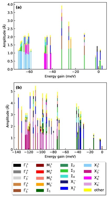
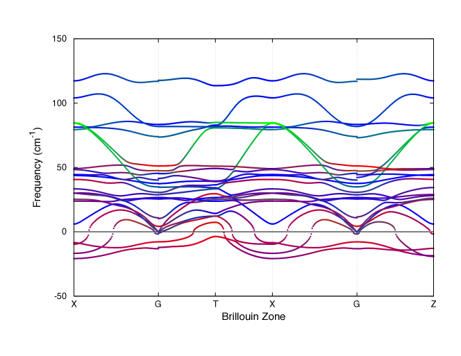
To gain a better understanding of how octahedral rotations lower the energy of RP halide perovskites, we proceeded by decomposing every structure into distortion modes. An overview of selected modes and the distortions they correspond to is shown in Table 3. For example, and modes in and , respectively, correspond to in-phase rotations along the in-plane - and -directions, whereas and describe the in- and out-of-phase rotation along the out-of-plane c-axis. The modes and correspond to equivalent tilt patterns but with different relative rotation between slabs A and B. Depending on which ions are affected by the mode, the tilt pattern occurs only in one or in both slabs. More complex tilt patterns like are a combination of these modes. Finally, the and modes describe polar displacements along the in-plane or out-of-plane -directions, respectively. Phonon dispersions (shown in Figure 5) for reveal symmetry breaking instabilities along several symmetry lines in the Brillouin zone, including the segment, dominated by octahedral tilts comprising I atom displacements. Similar results are expected for , where the additional inorganic layer increases the degree of cooperativity of octahedral tilts along the out-of-plane c-direction.
In Figures 2(a) and (b), we show the mode decomposition of every Cs2PbI4 and Cs3Pb2I7 structure as a function of the energy gain with respect to the parent compound. Each structure is composed of several distortion modes which we sorted such that the dominant mode with the largest amplitude is at the bottom of each bar. We normalize these amplitudes with respect to the parent cell so that amplitudes of different space groups of the same layer number are comparable. For in Figure 2(a), we observe a clear clustering of structures with the same dominant distortion mode. All of the lowest energy structures are dominated by an mode, followed by a group of structures dominated by an mode, and a group of structures with dominant mode. Within each cluster, structures can further be sorted based on their second-largest mode, in particular in the -dominated group, where structures with secondary distortion are lower in energy than those with as the second largest mode.
For in Figure 2(b), most of the dominant modes (specifically , , , , ) correspond to octahedral rotations. The large mode in the ground state structure with symmetry and the structure at -120 meV originates from an alternating shift of the Cs ions that breaks the centrosymmetry of these structures [25, 58]. In comparison to , the grouping of structures with similar dominant distortion modes is less distinct. Furthermore, unlike for where in particular the low-energy structures are dominated by two to three distortion modes, for multiple modes with similar amplitudes contribute to the overall distortion.
Overall, we find that for both Cs2PbI4 and Cs3Pb2I7, structures with a dominant mode corresponding to out-of-phase tilts in /-direction (, ) are energetically most favorable, followed by in-phase tilts in /-direction (, ). Rotation around the -axis (,) is mainly found in energetically higher structures.
4 Tuning of Band Gaps through Octahedral Rotations
Octahedral tilts are well-known to strongly affect the band gaps of 3D ABX3 perovskites [60, 61]. In these materials, octahedral tilts open the band gap because they lead to a stabilization of both the anti-bonding VBM and CBM with a larger energy reduction of the VBM due to the bond-length sensitivity of the Pb- lone pair that contributes to the VBM [26]. Here, we will explore to which extent different octahedral tilt patterns affect the band gap of RP halide perovskites. Unless otherwise noted, our band gaps are obtained with DFT-PBE calculations, without including SOC effects. Previous work has shown an error cancellation in the magnitude of DFT-PBE band gaps, since the spin-orbit splitting of the CBM’s Pb states lowers the band gap of Pb-based halide perovskite by 1 eV, whereas the inherent DFT band gap underestimation with semilocal functionals such as PBE leads to an underestimation of the band gap of similar size. We believe that this approach is justified in our case since we are only interested in trends and not in accurate band gap predictions. Furthermore, we have confirmed the accuracy of our reported band gap ranges by performing additional G0W0@PBE calculations including SOC, which gives reliable band gaps for a wide range of halide perovskites [62, 63, 64, 65].
The DFT-PBE band gaps of all structures of Cs2PbI4 and Cs3Pb2I7 can be found in Tables 1 and 2, respectively. Results for the bromides and chlorides are listed in the A and B, and follow similar trends. The Tables also report the -point at which the band gap of these semiconductors is located. In most cases, the band gap is direct at the point, or an equivalent high-symmetry point for non primitive unit cells after band unfolding. The band gaps of the structures with the lowest and highest band gap, and of the ground state structure are reported in Table 4. In both and , the band gap difference between the lowest- and the highest band gap structure is 0.3 eV, for all three halides. Our calculations confirm the error cancellation between SOC and quasiparticle corrections observed before [63], resulting in band gaps very close to the ones calculated with DFT-PBE. The ground state structure features a band gap right in between the range of accessible band gaps in all cases. Furthermore, the structure with the lowest band gap is the undistorted parent structure only in the case of Cs2PbI4, raising the question how exactly octahedral rotations affect the band gap of these materials.
| X site | ||||
|---|---|---|---|---|
| space group | Egap (eV) | space group | Egap (eV) | |
| I | 1.90 (1.87) | 1.77 | ||
| 2.18 (2.12) | 2.09 | |||
| 2.01 | 2.01 | |||
| Br | 2.27 | 2.10 | ||
| 2.55 | 2.40 | |||
| 2.38 | 2.35 | |||
| Cl | 2.68 | 2.52 | ||
| 2.99 | 2.81 | |||
| 2.84 | 2.78 | |||
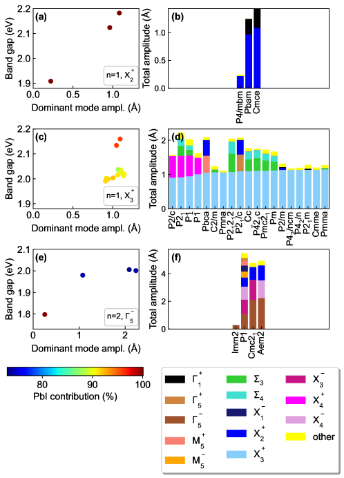
We proceeded by analysing the band gap variation in terms of dominant symmetry-mode distortions, distinguishing three classes of structures. In Figure 3, we illustrate the most important trends for three representative cases:
- 1.
-
2.
Second case: Structures with a large band gap variation that does not depend on the amplitude of the dominant mode, shown in Figures 3(c) and (d) for the case of Cs2PbI4 structures in which the dominant distortion mode is .
-
3.
Third case: Structures with no correlation between the amplitude of the dominant mode and the size of the band gap, shown in Figures 3(e) and (f) for the case of Cs3Pb2I7 with dominant mode.
It is important to note that considering all possible and structures, the correlation between band gap size and the amplitude of the dominant mode is weak. This is not surprising since the band gap is a macroscopic property of the material which is determined by an interplay of all modes. However, the picture barely changes when the second-largest mode is taken into account. These findings can be explained by analysing the amplitude of the dominant distortion mode in terms of its contributions from Pb- and I-displacements, since the band edges and hence the size of the band gap of these materials are derived from Pb and I (VBM) and Pb (CBM) orbitals, respectively. We calculate the percentage of the total amplitude, , corresponding to displacements of Pb and I, , as . This percentage contribution is shown in color in Figures 3(a), (c), and (e), respectively.
Our analysis shows that the influence of the mode on the band gap depends on the Pb-I contribution of the mode. For modes where the amplitude of the dominant mode leads to large band gap changes, as exemplified by our first case in Figure 3(a), the contribution is almost constant at 100%. For our second case in Figure 3(c), the dominant mode amplitude is 1 Å for a wide range of different structures with varying degrees of secondary and tertiary mode contributions. However, structures with dominant contribution primarily coming from Pb-I distortions have larger band gaps than those structures in which the distortion also contains significant Cs contributions. In the third case of Figure 3(e), the lowest band gap structure with symmetry is derived entirely from a mode with 100% PbI character (an off-center displacement of Pb), but the amplitude of the mode is very small. The mode of the other structures has a significantly lower PbI contribution, indicating that their large band gap originates from their secondary or modes which have amplitudes between 1.1 and 1.5 Å.
5 Magnitude of Rashba-/Dresselhaus Splitting in Polar Structures
We now focus on the band structure of Cs2PbI4 and Cs3Pb2I7 perovskites featuring a polar space group. Polar, i.e., non-centrosymmetric materials, with strong SOC in their electronic structure can exhibit Rashba- [33], Dresselhaus- [34], or mixed Rashba-/Dresselhaus-splitting. In all three cases, the defining characteristic is a splitting of the energy bands in -space, that we quantify by the parameter , with ER and kR as defined in Figure 4(a). In the following, we will not distinguish between pure and mixed Rashba and/or Dresselhaus cases and refer to the effect as Rashba-/Dresselhaus splitting. An in-depth exploration of these spin-textures can be found in Ref. [44].
We start by calculating the macroscopic electronic polarization of all polar Cs2PbI4 and Cs3Pb2I7 structures using the Berry phase approach and with the Born effective charge approximation. These values are given in Table 5 and are in very good agreement with each other. For Cs2PbI4 only the structures with and symmetry display a significant polarization () of 3.4 and 2.7 , respectively. For Cs3Pb2I7, the ground state structure with symmetry has a polarization of 1.9 . The two other phases with significant polarization are with 1.8 and with 1.6 , respectively. Note that these values are of the same order of magnitude as what was calculated for all-inorganics 3D ABX3 perovskites [38], but well below the polarization of typical oxide ferroelectrics.
| space group | pBerry | pBEC | space group | pBerry | pBEC | ||
|---|---|---|---|---|---|---|---|
| Pmc21 | 0.03 | 0.03 | 0.0 | Cmc21 | 1.91 | 1.93 | 0.0 |
| Cc | 0.02 | 0.02 | 0.0 | Cm | 0.04 | 0.03 | 0.0 |
| P1 | 0.01 | 0.01 | 0.0 | Pmn21 | 0.08 | 0.09 | 0.0 |
| P21 | 0.00 | 0.01 | 0.0 | Pmm2 | 0.01 | 0.01 | 0.0 |
| C2 | 0.04 | 0.04 | 0.0 | P2 | 0.02 | 0.01 | 0.0 |
| Pc | 3.44 | 3.20 | 0.9 | Aem2 | 1.75 | 1.78 | 0.0 |
| Pmn21 | 0.35 | 0.41 | 0.9 | P21 | 0.04 | 0.07 | 0.0 |
| Aea2 | 2.66 | 2.66 | 0.7 | P1 | 0.85 | 0.86 | 0.0 |
| Imm2 | 0.80 | 0.80 | 0.0 | Pma2 | 0.01 | 0.01 | 0.0 |
| I4mm | 0.12 | 0.12 | 0.0 | Pc | 0.78 | 0.77 | 0.0 |
| Fmm2 | 0.38 | 0.38 | 0.0 | Ama2 | 0.14 | 0.12 | 0.0 |
| Amm2 | 0.11 | 0.09 | 0.0 | ||||
| C2 | 0.25 | 0.24 | 0.0 | ||||
| Pm | 1.57 | 1.37 | 0.5 | ||||
| Pmc21 | 0.85 | 0.84 | 0.0 | ||||
| I4mm | 0.01 | 0.12 | 0.0 | ||||
| Imm2 | 0.73 | 0.73 | 0.0 | ||||
| Fmm2 | 2.10 | 1.81 | 0.0 | ||||
For evaluating the magnitude of the Rashba-/Dresselhaus effect, we calculated the band structure of all polar structures listed in Table 5 across the entire Brillouin zone including SOC self-consistently. The parameter was calculated by fitting a fourth-degree polynomial to the conduction band. For we additionally evaluated the parameter using a regular three-dimensional grid around the point to ensure that we are measuring the splitting in the reciprocal space direction where it is largest. The value reported in Table 5 refers to this calculation. Note that due to numerical accuracy, a Rashba-/Dresselhaus effect smaller than 0.1 eVÅ will not be resolved in our calculations.
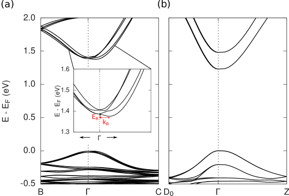
Our main finding is that even though a total of 27 structures have polar space groups in our study, a clear Rashba-/Dresselhaus effect at the CBM, i.e., around the point is only visible in four structures: , , and for Cs2PbI4 and for Cs3Pb2I7. For many of the analyzed structures this finding can simply be explained by the vanishing polarization of the structures. However, for some structures with significant polarization, for example the polar ground state of Cs3Pb2I7 and the structure, we also do not observe Rashba-/Dresselhaus splitting of the CBM or in the lowest-energy conduction band at other -points across the Brillouin zone. As shown below, this finding can be explained by the direction and Pb-I orbital contribution of the polar distortion mode.
In Cs2PbI4, all three structures with significant Rashba-/Dresselhaus splitting are dominated by a mode. In these structures, the initial octahedral tilting pattern results in enough symmetry breaking to allow for the appearance of the polar mode. Similarly, for Cs3Pb2I7, the structure with sizeable Rashba-/Dresselhaus effect is dominated by a mode. We note that the interoctahedral asymmetries studied by Jana et al. may also result in the appearance of the polar mode. However, as opposed to the case of quasi-2D hybrid perovskites, where octahedral tilt angle asymmetries in the inorganic monolayer arise out of distortions at the organic-inorganic interface, in all-inorganic RP perovskites, the polar mode arises from a combination of coherent mode distortions, that lead to a global polar symmetry. Notably, in the structures and , Rashba-/Dresselhaus splitting is not observed (see Figure 4(b)) because the polar mode primarily comprises Cs ion displacements which do not contribute electronically to the band edges. Finally, our results are also in agreement with Ref. [44], since all the structures displaying relatively large splitting contain polar atomic displacements towards an out-of-bond direction of the octahedron. However, we note that in equilibrium, and structures display small polarizations and negligible splitting effects despite their out-of-bond distortion.
6 Energy Landscape and Polarization of Free-Standing 2D Halide Perovskite Layers
Pb-based all-inorganic RP perovskites have at this point and to the best of our knowledge not been synthesized. However, a multitude of hybrid quasi-2D perovskites exist [6]. Additionally, these materials can be prepared as single crystal monolayers by mechanical exfoliation [14], prompting us to ask the question whether our findings for RP halide perovskites can be translated to mono- and bilayer halide perovskites. For this purpose we constructed mono- and bilayer slices from fully relaxed CsPbI3 and separated periodic repeat units by 20 Å of vacuum to avoid spurious interlayer interactions. The undistorted structure of this material class has symmetry. Inducing all possible tilt patterns to the reference structure as before results in 13 and 16 unique space groups for the mono- and bilayer case, respectively. Importantly, and in contrast to the RP perovskites, octahedral rotations cannot break inversion symmetry in the monolayer case. For the bilayer, we find four polar space groups. A list of space groups, their energies relative to the reference structure, and their DFT-PBE band gaps can be found in C.
The ground state structures for the mono- and bilayer have and symmetry and energy gains of -105 meV and -163 meV with respect to the reference structure, respectively. Similar to before, we find a clear energetic grouping of structures based on their dominant distortion mode. For the monolayer, structures with a dominant distortion, corresponding to an tilt pattern, i.e., out-of-phase rotation along the - and -directions, have the lowest energy, similar to the RP halide perovskites. This is followed by two structures with dominant mode () and another cluster with dominant () mode. This is different from the RP perovskites for which the in-phase rotation around the -direction was the energetically least favorable. For the bilayer, the energetic ordering in terms of dominant distortion modes is the same as for the RP perovskites. In particular, the polar structure which is dominated by a large mode is originating from an alternating shift of Cs ions which is responsible for a significant polarization of this structure.
In line with our results of Section 5, none of the polar bilayer structures exhibits Rashba-/Dresselhaus splitting, since in all cases structures with a significant polarization are dominated by either an in-bond mode or by a mode associated primarily with Cs displacements.
7 Discussion and Summary
Fully inorganic RP halide perovskites are challenging to synthesize, and in particular, Cs2PbI4 and Cs3Pb2I7 have not been experimentally realized yet. However, an RP perovskite Cs2PbI2Cl2 with corner-sharing octahedra in which I occupies the out-of-plane halide sites was reported by Li et al. in Ref. [66]. Furthermore, Yu et al. reported the formation of a RP phase in nanosheets of CsPbBr3, suggesting routes for stabilizing the RP phase through nanostructuring [67]. Since DFT calculations predict many all-inorganic RP halide perovskite compositions to be thermodynamically unstable [66], it is important to connect our findings to the much more common hybrid organic-inorganic RP halide perovskites. The energy landscape and structural distortions in these hybrid systems are determined by steric effects and interactions at the organic-inorganic interface, allowing for a wider range of distortions and other structural parameters such as the interlayer distance and stacking. Nonetheless, since band gaps and the Rashba-/Dresselhaus effect are determined by the inorganic sublattice, we expect our findings for the effect of octahedral tilts on the band structure and the emergence of Rashba-/Dresselhaus splitting to be of relevance for the hybrid systems as well.
We have here focused on RP halide perovskites with and . The main difference between these systems is that the extra layer in the system allows for a coherent octahedral tilting in the perovskite plane. The latter leads to a larger set of unique octahedral tilting distortions and more possibilities to induce polar distortions due to the combination of symmetry-breaking nonpolar octahedral rotations. For , we expect an increase in the cooperativity of the octahedral tilting in both in-plane and out-of-plane directions. The number and overall characteristics of the possible octahedral tilt patterns will remain similar due to the RP fault separating the perovskites layers. As the number of layers increases, we expect the interior layers, in the middle of the perovskite slab, to approach the rotation angle in the 3D perovskite . The perovskite layers near the fault may experience strain and smaller rotation angles, closer to the values, due the restrictions of the RP geometry. The latter suggests that, as increases, properties such as polarization, will become increasingly dominated by the perovskite slab as opposed to the layers near the fault. We expect polar structures with in-plane polarization to approach bulk 3D polar structures, with equivalent band gaps and polarization.
Rashba-/Dresselhaus splitting is expected for any structure without inversion symmetry and large spin-orbit interaction. In our case, Rashba-/Dresselhaus splitting is observed for polar structures with significant polarization. However, our work emphasizes that besides these basic ingredients, Rashba-/Dresselhaus splitting requires polar atomic displacements to be associated with band edge orbitals. While the computationally predicted Rashba-/Dresselhaus splitting is larger for 3D perovskite or large with dominant perovskite layer over the RP fault, polar structures are increasingly less stable for . Therefore, the observation of the Rashba-/Dresselhaus effect is increasingly less likely for large . In contrast, whereas Rashba-/Dresselhaus splitting is smaller for the possible polar structures with and , these polar structures are close to the ground state and therefore more likely to be observed experimentally. In this context, we emphasize that the and systems are fundamentally different from RP perovskites with finite , and deserve separate analysis. For finite , the RP fault inevitably leads to multiple octahedral tiltings, and Rashba-/Dresselhaus splitting analogous to as studied in our work and by Maurer et al for [44]. With increasing , we expect the perovskite layers in the RP structure to dominate and converge to the values of 3D perovskites.
We note that octahedral tilting distortions are ubiquitous in halide perovskites (as well as in oxide perovskites and related materials). In 3D perovskites, these distortions are not polar and cannot induce ferroelectricity [68]. As is well-known for oxide and shown explicitly here for halide perovskites, layering in RP structures can lead to a sizable electric polarization due to the coupling of rotational modes [28]. RP halide perovskites therefore also have potential applications as ferroelectrics if a significant switchable electric polarization can be achieved [69]. But also in photovoltaic applications a macroscopic electric polarization can be beneficial due to its connection to the bulk photovoltaic effect [70]. Furthermore, since polar structures with strong spin-orbit coupling can feature a sizable Rashba-/Dresselhaus splitting, applications in spin-orbitronics can also be envisioned [32]. Finally, RP structures can be used to achieve quantum confinement effects in halide perovskites [71].
In summary, we have systematically studied the complex energetic and electronic structure landscape of all-inorganic RP halide perovskites. Octahedral tilts allow for band gap changes comparable to those associated with halide substitution in these materials. We find a multitude of polar structures for both and RP halide perovskites; contrary to 3D ABX3 perovskites polar space groups are accessible via octahedral tilts in RP perovskites. However, many of these polar structures have only very small polarization and only four display a significant Rashba-/Dresselhaus splitting in the CBM due to the direction and Pb-I contribution of their dominant polar distortion mode. This situation is even more pronounced in mono- and bilayers of these materials, since the lack of a ”stacked” or layered structure as present in the RP perovskites reduces the amount of possibilities for generating polar structures via octahedral tilts.
Experimentally, targeted structural distortions could be induced through layering with organic molecules as has been demonstrated for a variety of RP halide perovskites [21, 43, 72]. Another powerful tool for tailoring structural properties of perovskites is strain induced by epitaxial growth. For oxides, strain has been shown to dramatically change the energy landscape [73, 74] and lead to functional properties [75, 76, 77]. Recently, targeted epitaxial growth has been reported for halide perovskites [78], opening new routes to tune optoelectronic properties for photovoltaic applications and beyond.
Appendix A Data for Other Halides with n=1
This Appendix provides a Table with tilt patterns, energies, and band gaps of the bromide and chloride RP perovskites not reported in the main text, as well as the phonon band structure of Cs2PbI4 computed as described in Section 2.
| Cs2PbBr4 | Cs2PbCl4 | |||||||
|---|---|---|---|---|---|---|---|---|
| space group | tilt pattern | -point | E (meV) | band gap (eV) | E (meV) | band gap (eV) | ||
| 1 | P1 | a-a+a0/a-a+a+ | 111 | -48.64 | 2.35 | -43.11 | 2.78 | |
| 2 | P | a0b-b+/a0b-b+ | 11-1 | Z | -49.81 | 2.35 | -44.14 | 2.77 |
| 4 | P21 | a+a-a+/a+a-a+ | 111 | -49.25 | 2.35 | -43.84 | 2.77 | |
| 5 | C2 | a-a+a+/a+a-a+ | 111 | -31.89 | 2.38 | -25.69 | 2.77 | |
| 6 | Pm | a-a+a+/a0a+a0 | 111 | -55.70 | 2.39 | -50.65 | 2.84 | |
| 7 | Pc | a+b+b+/a+b+b+ | 11-1 | -16.42 | 2.45 | -11.46 | 2.87 | |
| 9 | Cc | a-a+a+/a+a-a+ | 1-11 | -55.77 | 2.39 | -50.63 | 2.84 | |
| 10 | P2/m | a-a0a+/a0a+a0 | 111 | -55.89 | 2.39 | -50.79 | 2.84 | |
| 11 | P21/m | a-a0a0/a0a+a+ | 111 | -55.96 | 2.39 | -50.85 | 2.84 | |
| 12 | C2/m | a-a-a0/a+a+a0 | 111 | -47.94 | 2.32 | -42.97 | 2.73 | |
| 13 | P2/c | a-b-c0/a-b-c0 | 1-11 | -49.59 | 2.35 | -43.23 | 2.79 | |
| 14 | P21/c | a0b-b+/a0b-b+ | 111 | Y | -47.03 | 2.47 | -41.98 | 2.85 |
| 15 | C2/c | a0a-c+/a0a-c+ | 111 | -27.61 | 2.45 | -21.61 | 2.87 | |
| 18 | P21212 | a-a+a0/a+a0a0 | 111 | -55.38 | 2.39 | -50.11 | 2.84 | |
| 26 | Pmc21 | a-a+a0/a0a+a0 | 111 | -54.51 | 2.39 | -50.65 | 2.84 | |
| 31 | Pmn21 | a0a+a0/a0a+a+ | 111 | -13.06 | 2.41 | -9.49 | 2.83 | |
| 41 | Aea2 | a+a+a+/a+a+a+ | 11-1 | -5.22 | 2.38 | -4.43 | 2.79 | |
| 51 | Pmma | a-a0a0/a0a+a0 | 111 | -55.94 | 2.39 | -50.74 | 2.84 | |
| 53 | Pmna | a-a-a0/a0a0a0 | 111 | -48.75 | 2.32 | -43.44 | 2.72 | |
| 55 | Pbam | a0a0a+/a0a0c+ | 111 | 1.89 | 2.51 | -0.04 | 2.95 | |
| 56 | Pccn | a-a-c+/a-a-c+ | 111 | -29.97 | 2.47 | -24.08 | 2.88 | |
| 57 | Pbcm | a-a0a0/a+a-a0 | 111 | -31.84 | 2.36 | -25.86 | 2.80 | |
| 59 | Pmmn | a0a0a0/a0a+a+ | 111 | 0.79 | 2.27 | -0.25 | 2.71 | |
| 61 | Pbca | a-a-c+/a-a-c+ | -1-1-1 | -50.01 | 2.48 | -44.42 | 2.90 | |
| 62 | Pnma | a0a+c0/a0a+c0 | 111 | X | -12.28 | 2.40 | -8.48 | 2.84 |
| 64 | Cmce | a0a0c+/a0a0c+ | 111 | 3.12 | 2.55 | 0.95 | 2.99 | |
| 66 | Cccm | a-a-c0/a-a-c0 | 111 | -29.40 | 2.28 | -23.33 | 2.68 | |
| 67 | Cmme | a-a0a0/a0a0a0 | 111 | -56.61 | 2.39 | -51.18 | 2.84 | |
| 85 | P4/n | a0a0a+/a+a+a0 | 111 | 1.38 | 2.36 | -0.02 | 2.80 | |
| 86 | P42/n | a-a-c0/a-a-c0 | 1-11 | -56.61 | 2.39 | -51.08 | 2.84 | |
| 94 | P42212 | a-a+a0/a+a-a0 | 111 | -31.28 | 2.38 | -26.02 | 2.80 | |
| 114 | P21c | a-a+a0/a+a-a0 | 1-11 | -55.81 | 2.39 | -50.65 | 2.84 | |
| 127 | P4/mbm | a0a0a0/a0a0a+ | 111 | 1.41 | 2.27 | 0.43 | 2.71 | |
| 129 | P4/nmm | a0a0a0/a+a+a0 | 111 | 1.21 | 2.27 | 0.01 | 2.71 | |
| 134 | P42/nnm | a-a0a0/a0a-a0 | 111 | -33.18 | 2.36 | -27.03 | 2.80 | |
| 137 | P42/nmc | a0a+a0/a+a0a0 | 111 | -0.71 | 2.34 | -1.20 | 2.78 | |
| 138 | P42/ncm | a-a0a0/a0a-a0 | 1-11 | -56.58 | 2.39 | -51.09 | 2.84 | |
| 139 | I4/mmm | a0a0a0/a0a0a0 | 111 | 0.00 | 2.27 | 0.00 | 2.71 | |
| 42 | Fmm2 | a0a0a0/a0a0a0 | 111 | M | 0.00 | 2.27 | -0.01 | 2.71 |
| 44 | Imm2 | a0a0a0/a0a0a0 | 111 | M | -0.28 | 2.31 | -0.11 | 2.76 |
| 107 | I4mm | a0a0a0/a0a0a0 | 111 | -0.05 | 2.27 | 0.01 | 2.72 | |
Appendix B Data for Other Halides with n=2
The following Table contains tilt patterns, energies, and band gaps for the bromide and chloride RP perovskites not reported in the main text.
| Cs3Pb2Br7 | Cs3Pb2Cl7 | |||||||
|---|---|---|---|---|---|---|---|---|
| space group | tilt pattern | -point | E (meV) | band gap (eV) | E (meV) | band gap (eV) | ||
| 1 | P1 | a-a-a-/a-a-a+ | 1-11 | -81.32 | 2.30 | -72.51 | 2.71 | |
| 2 | P | a0b-b-/a0b-b- | 111 | Z | -96.31 | 2.21 | -86.08 | 2.64 |
| 3 | P2 | a-a0a-/a0a+a+ | 111 | -94.65 | 2.24 | -87.04 | 2.67 | |
| 4 | P21 | a+a-a-/a+a-a- | 11-1 | -80.91 | 2.29 | -85.24 | 2.64 | |
| 5 | C2 | a-a-a-/a+a+a- | 111 | -82.42 | 2.27 | -76.71 | 2.67 | |
| 6 | Pm | a+b+b+/a+b+b+ | 11-1 | -95.50 | 2.21 | -85.26 | 2.64 | |
| 7 | Pc | a-a-a-/a-a-a+ | 111 | -70.85 | 2.29 | -62.36 | 2.73 | |
| 8 | Cm | a0b-b+/a0b-b+ | 111 | -96.74 | 2.21 | -86.04 | 2.65 | |
| 10 | P2/m | a-b-c0/a-b-c0 | 1-11 | -96.75 | 2.21 | -86.22 | 2.65 | |
| 11 | P21/m | a+a-c0/a+a-c0 | 111 | -95.04 | 2.21 | -85.15 | 2.64 | |
| 12 | C2/m | a0a-c0/a0a-c0 | 111 | -96.67 | 2.21 | -86.13 | 2.64 | |
| 13 | P2/c | a-a-a-/a-a-a- | 111 | -61.46 | 2.30 | -55.20 | 2.70 | |
| 14 | P21/c | a0b-b-/a0b-b- | 11-1 | -96.58 | 2.21 | -86.03 | 2.64 | |
| 15 | C2/c | a-a-a-/a-a-a- | -1-1-1 | -80.26 | 2.30 | -74.40 | 2.69 | |
| 16 | P222 | a0a0a-/a0a+a+ | 111 | -24.84 | 2.20 | -25.46 | 2.64 | |
| 17 | P2221 | a0a0a+/a0a+a- | 111 | -27.23 | 2.24 | -26.61 | 2.68 | |
| 20 | C2221 | a+a+a-/a+a+a- | 111 | -47.83 | 2.28 | -42.17 | 2.68 | |
| 21 | C222 | a0a0a-/a+a+a- | 111 | -23.77 | 2.27 | -24.87 | 2.70 | |
| 25 | Pmm2 | a-a0a0/a0a+a+ | 111 | -94.91 | 2.24 | -87.14 | 2.67 | |
| 26 | Pmc21 | a-a-a0/a-a-a+ | 111 | -67.23 | 2.26 | -60.07 | 2.66 | |
| 28 | Pma2 | a-a0a+/a0a-a+ | 111 | -74.56 | 2.24 | -65.70 | 2.67 | |
| 31 | Pmn21 | a-a0a+/a0a-a+ | 1-11 | -96.31 | 2.24 | -87.85 | 2.68 | |
| 36 | Cmc21 | a-a-a+/a-a-a+ | -1-1-1 | -102.22 | 2.35 | -90.41 | 2.78 | |
| 38 | Amm2 | a-a-a0/a+a+a0 | 111 | -77.87 | 2.23 | -72.76 | 2.62 | |
| 39 | Aem2 | a-a-a+/a-a-a+ | 111 | -82.91 | 2.34 | -71.13 | 2.76 | |
| 40 | Ama2 | a+a+a+/a+a+a+ | 11-1 | -72.35 | 2.25 | -63.57 | 2.68 | |
| 47 | Pmmm | a-a0a0/a0a+a0 | 111 | -95.48 | 2.24 | -87.32 | 2.68 | |
| 49 | Pccm | a0a0a-/a0a+a0 | 111 | -25.06 | 2.19 | -25.91 | 2.64 | |
| 50 | Pban | a0a0a-/a0a0c- | 111 | -25.82 | 2.39 | -27.68 | 2.81 | |
| 51 | Pmma | a-a-a0/a0a0a0 | 111 | -79.52 | 2.23 | -74.22 | 2.62 | |
| 54 | Pcca | a-a-a-/a-a-a- | 11-1 | -64.59 | 2.28 | -57.77 | 2.68 | |
| 55 | Pbam | a0a0a+/a0a0c+ | 111 | -24.65 | 2.37 | -26.04 | 2.78 | |
| 57 | Pbcm | a-a-a+/a-a-a+ | 11-1 | -78.79 | 2.33 | -67.55 | 2.76 | |
| 59 | Pmmn | a0a+c0/a0a+c0 | 111 | X | -45.74 | 2.23 | -39.10 | 2.66 |
| 60 | Pbcn | a-a-a-/a-a-a- | -1-11 | -83.82 | 2.30 | -77.37 | 2.70 | |
| 62 | Pnma | a-a-a+/a-a-a+ | -1-11 | -97.29 | 2.34 | -86.24 | 2.77 | |
| 63 | Cmcm | a-a-c0/a-a-c0 | -1-11 | -79.34 | 2.23 | -73.97 | 2.63 | |
| 64 | Cmce | a0a0c+/a0a0c+ | 111 | -24.33 | 2.38 | -25.85 | 2.79 | |
| 65 | Cmmm | a-a0a0/a0a0a0 | 111 | -96.34 | 2.24 | -87.38 | 2.68 | |
| 66 | Cccm | a-a+a0/a+a-a0 | 111 | -71.02 | 2.26 | -62.54 | 2.68 | |
| 67 | Cmme | a-a-c0/a-a-c0 | 111 | -60.24 | 2.22 | -53.62 | 2.60 | |
| 68 | Ccce | a0a0c-/a0a0c- | 111 | -25.56 | 2.40 | -27.54 | 2.82 | |
| 81 | P | a0a0a+/a+a+a- | 111 | -25.05 | 2.28 | -24.43 | 2.69 | |
| 83 | P4/m | a0a0a+/a+a+a0 | 111 | -21.80 | 2.24 | -23.08 | 2.67 | |
| 84 | P42/m | a-a-c0/a-a-c0 | 1-11 | -96.16 | 2.24 | -87.38 | 2.68 | |
| 89 | P422 | a0a0a-/a+a+a0 | 111 | -23.40 | 2.24 | -23.57 | 2.67 | |
| 115 | Pm2 | a0a0a0/a+a+a- | 111 | -10.31 | 2.11 | -11.31 | 2.52 | |
| 117 | Pb2 | a0a0a-/a0a0a+ | 111 | -25.12 | 2.38 | -26.76 | 2.80 | |
| 123 | P4/mmm | a0a0a0/a+a+a0 | 111 | -10.35 | 2.10 | -11.36 | 2.52 | |
| 125 | P4/nbm | a0a0a-/a0a0a0 | 111 | -3.94 | 2.10 | -6.82 | 2.52 | |
| 127 | P4/mbm | a0a0a0/a0a0a+ | 111 | -3.48 | 2.10 | -6.25 | 2.52 | |
| 131 | P42/mmc | a0a+a0/a+a0a0 | 111 | -29.81 | 2.20 | -28.47 | 2.63 | |
| 132 | P42/mcm | a-a0a0/a0a-a0 | 111 | -74.44 | 2.24 | -65.55 | 2.67 | |
| 136 | P42/mnm | a-a0a0/a0a-a0 | 1-11 | -96.28 | 2.24 | -87.73 | 2.68 | |
| 139 | I4/mmm | a0a0c0/a0a0a0 | 111 | 0.00 | 2.10 | 0.00 | 2.52 | |
| 42 | Fmm2 | a0a0c0/a0a0a0 | 111 | M | -0.09 | 2.10 | -0.02 | 2.52 |
| 44 | Imm2 | a0a0c0/a0a0a0 | 111 | M | -0.18 | 2.12 | 0.02 | 2.55 |
| 107 | I4mm | a0a0c0/a0a0a0 | 111 | 0.11 | 2.10 | 0.07 | 2.52 | |
Appendix C Data for Free-Standing Mono- and Bilayer Perovskites
The following Table contains tilt patterns, energies, and band gaps of the mono- and bilayer perovskites of Section 6.
| Cs2PbI4 | ||||
|---|---|---|---|---|
| space group | tilt pattern | -point | E (meV) | band gap (eV) |
| P | a-b-a+ | Z | -104.57 | 2.16 |
| P21/m | a-a+a+ | -96.99 | 1.98 | |
| C2/m | a-a0a+ | -99.90 | 1.94 | |
| P2/c | a-b-a0 | -96.57 | 1.95 | |
| P21/c | a-a-a+ | -97.62 | 2.13 | |
| Pmma | a0a+a0 | X | -10.59 | 1.90 |
| Pmna | a-a-a0 | Z | -91.32 | 1.94 |
| Pbcm | a-a+a0 | -97.12 | 1.98 | |
| Pmmn | a0a+a+ | -33.76 | 2.23 | |
| Cmme | a-a0a0 | -100.15 | 1.94 | |
| P4/mmm | a0a0a0 | M | 0.00 | 1.84 |
| P4/mbm | a0a0a+ | -34.53 | 2.24 | |
| P4/nmm | a+a+a0 | -6.15 | 1.97 | |
| Cs3Pb2I7 | ||||
|---|---|---|---|---|
| space group | tilt pattern | -point | E (meV) | band gap (eV) |
| P | a-b-a- | -162.45 | 1.86 | |
| Pm | a-b-a+ | -132.38 | 1.92 | |
| P2/m | a-b-a0 | -162.37 | 1.86 | |
| P21/m | a-a+a- | -155.06 | 2.05 | |
| C2/m | a-a0a- | -162.38 | 1.86 | |
| P2/c | a-a-a- | B | -124.77 | 1.98 |
| Pmm2 | a-a+a+ | -160.55 | 1.87 | |
| Pmc21 | a-a-a+ | -157.30 | 2.03 | |
| Amm2 | a-a0a+ | -162.24 | 1.86 | |
| Pmmm | a0a+a0 | U | -57.54 | 1.82 |
| Pmma | a-a-a0 | -117.77 | 1.92 | |
| Cmmm | a-a0a0 | -162.81 | 1.86 | |
| Pm2 | a+a+a- | -43.66 | 1.96 | |
| P4/mmm | a0a0a0 | M | 0.00 | 1.76 |
| P4/nbm | a0a0a- | -37.89 | 2.07 | |
| P4/mbm | a0a0a+ | -36.63 | 2.07 | |
Acknowledgments
We acknowledge computational resources provided by the Bavarian Polymer Center at the University of Bayreuth, Germany, the Dutch national supercomputing center Snellius supported by the SURF Cooperative and PRACE for awarding access to the Marconi100 supercomputer at CINECA, Italy. N.F.-C. and S.E.R.-L. acknowledges ANID Fondecyt Regular grant number 1220986. Powered@NLHPC: This research was partially supported by the supercomputing infrastructure of the NLHPC (ECM-02).
References
References
- [1] Mitzi D B, Wang S, Feild C A, Chess C A and Guloy A M 1995 Science 267 1473 URL http://www.ncbi.nlm.nih.gov/pubmed/17743545
- [2] Mitzi D B 1996 Inorg. Chem. Chem. 1669 7614–7619
- [3] Saparov B and Mitzi D B 2016 Chem. Rev. 116 4558–4596 URL https://doi.org/10.1021/acs.chemrev.5b00715
- [4] Tsai H, Nie W, Blancon J C, Stoumpos C C, Asadpour R, Harutyunyan B, Neukirch A J, Verduzco R, Crochet J J, Tretiak S, Pedesseau L, Even J, Alam M A, Gupta G, Lou J, Ajayan P M, Bedzyk M J, Kanatzidis M G and Mohite A D 2016 Nature 536 312 URL http://www.nature.com/doifinder/10.1038/nature18306
- [5] Stoumpos C C, Cao D H, Clark D J, Young J, Rondinelli J M, Jang J I, Hupp J T and Kanatzidis M G 2016 Chem. Mater. 28 2852–2867
- [6] Smith M D, Crace E J, Jaffe A and Karunadasa H I 2018 Ann. Rev. Mater. Res. 48 111–136 URL https://www.annualreviews.org/doi/10.1146/annurev-matsci-070317-124406
- [7] Blancon J C, Stier A V, Tsai H, Nie W, Stoumpos C C, Traoré B, Pedesseau L, Kepenekian M, Katsutani F, Noe G T, Kono J, Tretiak S, Crooker S A, Katan C, Kanatzidis M G, Crochet J J, Even J and Mohite A D 2018 Nature Comm. 9 2254 URL http://dx.doi.org/10.1038/s41467-018-04659-x
- [8] Even J, Pedesseau L and Katan C 2014 ChemPhysChem 15 3733–3741
- [9] McNulty J A and Lightfoot P 2021 IUCrJ 8 485–513 URL https://journals.iucr.org/m/issues/2021/04/00/yc5031/
- [10] Gao Y, Shi E, Deng S, Shiring S B, Snaider J M, Liang C, Yuan B, Song R, Janke S M, Liebman-Peláez A, Yoo P, Zeller M, Boudouris B W, Liao P, Zhu C, Blum V, Yu Y, Savoie B M, Huang L and Dou L 2019 Nat. Chem. 11 1151 – 1157
- [11] Connor B A, Leppert L, Smith M D, Neaton J B and Karunadasa H I 2018 J. Am. Chem. Soc. 140 5235–5240 URL http://pubs.acs.org/doi/10.1021/jacs.8b01543
- [12] Connor B A, Biega R I, Leppert L and Karunadasa H I 2020 Chem. Sci. 11 7708–7715 URL http://dx.doi.org/10.1039/D0SC01580F
- [13] Coffey A H, Yang S J, Gómez M, Finkenauer B P, Terlier T, Zhu C and Dou L 2022 Adv. Energy Mat. 2201501 URL https://onlinelibrary.wiley.com/doi/abs/10.1002/aenm.202201501
- [14] Yaffe O, Chernikov A, Norman Z M, Zhong Y, Velauthapillai A, van der Zande A, Owen J S and Heinz T F 2015 Phys. Rev. B 92 045414 URL http://link.aps.org/doi/10.1103/PhysRevB.92.045414
- [15] Aubrey M L, Saldivar Valdes A, Filip M R, Connor B A, Lindquist K P, Neaton J B and Karunadasa H I 2021 Nature 597 355–359 URL https://www.nature.com/articles/s41586-021-03810-x
- [16] Shi E, Yuan B, Shiring S B, Gao Y, Akriti, Guo Y, Su C, Lai M, Yang P, Kong J, Savoie B M, Yu Y and Dou L 2020 Nature 580 614 – 620
- [17] Pedesseau L, Sapori D, Traore B, Robles R, Fang H H, Loi M A, Tsai H, Nie W, Blancon J C, Neukirch A, Tretiak S, Mohite A D, Katan C, Even J and Kepenekian M 2016 ACS Nano 10 9776–9786
- [18] Cortecchia D, Neutzner S, Yin J, Salim T, Srimath Kandada A R, Bruno A, Lam Y M, Martí-Rujas J, Petrozza A and Soci C 2018 APL Materials 6 114207 URL https://aip.scitation.org/doi/10.1063/1.5045782
- [19] Fridriksson M B, van der Meer N, de Haas J and Grozema F C 2020 The Journal of Physical Chemistry C 124 28201–28209
- [20] Dhanabalan B, Leng Y c, Bi G, Lin M l, Tan P h, Infante I, Manna L, Arciniegas M P and Krahne R 2020 ACS Nano 14 4689
- [21] Jana M K, Song R, Liu H, Khanal D R, Janke S M, Zhao R, Liu C, Valy Vardeny Z, Blum V and Mitzi D B 2020 Nature Comm. 11 4699 ISSN 20411723 publisher: Springer US URL http://dx.doi.org/10.1038/s41467-020-18485-7
- [22] Menahem M, Dai Z, Aharon S, Sharma R, Asher M, Diskin-Posner Y, Korobko R, Rappe A M and Yaffe O 2021 ACS Nano 15 10153–10162 ISSN 1936086X
- [23] Li X, Hoffman J M and Kanatzidis M G 2021 Chem. Rev. 121 2230–2291 URL https://doi.org/10.1021/acs.chemrev.0c01006
- [24] Filip M R, Qiu D Y, Del Ben M and Neaton J B 2022 Nano Lett. URL https://pubs.acs.org/doi/10.1021/acs.nanolett.2c01306
- [25] Mulder A T, Benedek N A, Rondinelli J M and Fennie C J 2013 Adv. Funct. Mater. 23 4810–4820 URL https://onlinelibrary.wiley.com/doi/abs/10.1002/adfm.201300210
- [26] Zhao X G, Wang Z, Malyi O I and Zunger A 2021 Materials Today 49 107–122 URL https://doi.org/10.1016/j.mattod.2021.05.021
- [27] Benedek N a and Fennie C J 2013 J. Phys. Chem. C 117 13339
- [28] Benedek N A and Fennie C J 2011 Phys. Rev. Lett. 106 107204
- [29] Birol T, Benedek N A and Fennie C J 2011 Phys. Rev. Lett. 107 257602
- [30] Balachandran P V, Puggioni D and Rondinelli J M 2014 Inorg. Chem. 53 336–348
- [31] Even J, Pedesseau L, Katan C, Kepenekian M, Lauret J S, Sapori D and Deleporte E 2015 J. Phys. Chem. C 10161-10177 URL http://dx.doi.org/10.1021/acs.jpcc.5b00695
- [32] Kepenekian M and Even J 2017 J. Phys. Chem. Lett. 8 3362–3370 URL http://pubs.acs.org/doi/abs/10.1021/acs.jpclett.7b01015
- [33] Rashba E 1960 Sov. Phys. Solid State 2 1109–1122
- [34] Dresselhaus G 1955 Phys. Rev. B 100 580–586
- [35] Manchon A, Koo H C, Nitta J, Frolov S M and Duine R a 2015 Nature Mat. 14 871–882 URL http://www.nature.com/doifinder/10.1038/nmat4360
- [36] Yang Y, Yang M, Zhu K, Johnson J C, Berry J J, van de Lagemaat J and Beard M C 2016 Nature Comm. 7 12613 URL http://www.nature.com/doifinder/10.1038/ncomms12613
- [37] Bourelle S A, Camargo F V A, Ghosh S, Neumann T, van de Goor T W J, Shivanna R, Winkler T, Cerullo G and Deschler F 2022 Nature Communications 13 3320 URL https://www.nature.com/articles/s41467-022-30953-w
- [38] Leppert L, Reyes-Lillo S E and Neaton J B 2016 J. Phys. Chem. Lett. 7 3683–3689 URL https://pubs.acs.org/doi/full/10.1021/acs.jpclett.6b01794
- [39] Zheng F, Tan L Z, Liu S and Rappe A M 2015 Nano Lett. 15 7794–7800 URL https://pubs.acs.org/doi/10.1021/acs.nanolett.5b01854
- [40] Etienne T, Mosconi E and De Angelis F 2016 J. Phys. Chem. Lett. 7 1638–1645 URL http://dx.doi.org/10.1021/acs.jpclett.6b00564
- [41] Frohna K, Deshpande T, Harter J, Peng W, Barker B A, Neaton J B, Louie S G, Bakr O M, Hsieh D and Bernardi M 2018 Nature Comm. 9 1829 URL http://www.nature.com/articles/s41467-018-04212-w
- [42] Davies C L, Filip M R, Patel J B, Crothers T W, Verdi C, Wright A D, Milot R L, Giustino F, Johnston M B and Herz L M 2018 Nature Comm. 9 293 URL http://dx.doi.org/10.1038/s41467-017-02670-2
- [43] Jana M K, Song R, Xie Y, Zhao R, Sercel P C, Blum V and Mitzi D B 2021 Nature Comm. 12 4982 URL http://dx.doi.org/10.1038/s41467-021-25149-7
- [44] Maurer B, Vorwerk C and Draxl C 2022 Phys. Rev. B 105 155149 URL https://journals.aps.org/prb/abstract/10.1103/PhysRevB.105.155149
- [45] Kresse G and Furthmüller J 1996 Phys. Rev. B 54(16) 11169–11186 URL https://link.aps.org/doi/10.1103/PhysRevB.54.11169
- [46] Kresse G and Furthmüller J 1996 Comput. Mater. Sci. 6 15–50 URL https://www.sciencedirect.com/science/article/pii/0927025696000080
- [47] Kresse G and Joubert D 1999 Phys. Rev. B 59 1758–1775 URL http://link.aps.org/doi/10.1103/PhysRevB.59.1758
- [48] Perdew J P, Burke K and Ernzerhof M 1996 Phys. Rev. Lett. 77 3865–3868 URL http://www.ncbi.nlm.nih.gov/pubmed/10062328
- [49] Campbell B J, Stokes H T, Tanner D E and Hatch D M 2006 J. Appl. Cryst. 39 607–614 URL https://doi.org/10.1107/S0021889806014075
- [50] Togo A and Tanaka I 2015 Scripta Materialia 108 1–5 URL https://doi.org/10.1016/j.scriptamat.2015.07.021
- [51] Giannozzi P, Baroni S, Bonini N, Calandra M, Car R, Cavazzoni C, Ceresoli D, Chiarotti G L, Cococcioni M, Dabo I, Dal Corso A, De Gironcoli S, Fabris S, Fratesi G, Gebauer R, Gerstmann U, Gougoussis C, Kokalj A, Lazzeri M, Martin-Samos L, Marzari N, Mauri F, Mazzarello R, Paolini S, Pasquarello A, Paulatto L, Sbraccia C, Scandolo S, Sclauzero G, Seitsonen A P, Smogunov A, Umari P and Wentzcovitch R M 2009 J. Phys.: Cond. Matt. 21 395502 URL https://iopscience.iop.org/article/10.1088/0953-8984/21/39/395502
- [52] Giannozzi P, Andreussi O, Brumme T, Bunau O, Buongiorno Nardelli M, Calandra M, Car R, Cavazzoni C, Ceresoli D, Cococcioni M, Colonna N, Carnimeo I, Dal Corso A, De Gironcoli S, Delugas P, Distasio R A, Ferretti A, Floris A, Fratesi G, Fugallo G, Gebauer R, Gerstmann U, Giustino F, Gorni T, Jia J, Kawamura M, Ko H Y, Kokalj A, Kücükbenli E, Lazzeri M, Marsili M, Marzari N, Mauri F, Nguyen N L, Nguyen H V, Otero-De-La-Roza A, Paulatto L, Poncé S, Rocca D, Sabatini R, Santra B, Schlipf M, Seitsonen A P, Smogunov A, Timrov I, Thonhauser T, Umari P, Vast N, Wu X and Baroni S 2017 J. Phys.: Cond. Matt. 29 465901 URL https://iopscience.iop.org/article/10.1088/1361-648X/aa8f79
- [53] van Setten M J, Giantomassi M, Bousquet E, Verstraete M J, Hamann D R, Gonze X and Rignanese G M 2018 Comp. Phys. Comm. 226 39–54
- [54] Deslippe J, Samsonidze G, Strubbe D A, Jain M, Cohen M L and Louie S G 2012 Comp. Phys. Comm. 183 1269–1289 URL http://dx.doi.org/10.1016/j.cpc.2011.12.006
- [55] Li S and Birol T 2020 npj Comp. Mater. 6 168 URL https://www.nature.com/articles/s41524-020-00436-x
- [56] Zhang Y, Sahoo M P K, Shimada T, Kitamura T and Wang J 2017 Phys. Rev. B 96 144110 URL https://link.aps.org/doi/10.1103/PhysRevB.96.144110
- [57] Wang C, Zhang M, Wang R, Zhang C, Meng X, Xi Y, Li S and Yan H 2021 J. Phys. Chem. C 125 13971–13983 URL https://doi.org/10.1021/acs.jpcc.1c00720
- [58] Wang H, Gou G and Li J 2016 Nano Energy 22 507–513 URL https://www.sciencedirect.com/science/article/pii/S2211285516000872
- [59] Travis W, Glover E N K, Bronstein H, Scanlon D O and Palgrave R G 2016 Chemical Science 7 4548–4556 URL https://pubs.rsc.org/en/content/articlelanding/2016/sc/c5sc04845a
- [60] Filip M R, Eperon G E, Snaith H J and Giustino F 2014 Nat. Comm. 5 5757 URL http://www.nature.com/doifinder/10.1038/ncomms6757
- [61] Wiktor J, Rothlisberger U and Pasquarello A 2017 J. Phys. Chem. Lett. 8 5507–5512
- [62] Umari P, Mosconi E and de Angelis F 2014 Sci. Rep. 4 4467 URL https://www.nature.com/articles/srep04467
- [63] Filip M R and Giustino F 2014 Phys. Rev B 90 245145 URL http://link.aps.org/doi/10.1103/PhysRevB.90.245145
- [64] Filip M R, Hillman S, Haghighirad A A, Snaith H J and Giustino F 2016 J. Phys. Chem. Lett. 7 2579–2585 URL http://pubs.acs.org/doi/abs/10.1021/acs.jpclett.6b01041
- [65] Leppert L, Rangel T and Neaton J B 2019 Phys. Rev. Materials 3 103803 URL https://journals.aps.org/prmaterials/abstract/10.1103/PhysRevMaterials.3.103803
- [66] Li J, Yu Q, He Y, Stoumpos C C, Niu G, Trimarchi G G, Guo H, Dong G, Wang D, Wang L and Kanatzidis M G 2018 J. Am. Chem. Soc. 140 11085–11090 URL https://doi.org/10.1021/jacs.8b06046
- [67] Yu Y, Zhang D and Yang P 2017 Nano Lett. 17 5489–5494 URL https://doi.org/10.1021/acs.nanolett.7b02146
- [68] Young J, Lalkiya P and Rondinelli J M 2016 J. Mater. Chem. C 4 4016–4027
- [69] Zhang Y, Parsonnet E, Fernandez A, Griffin S M, Huyan H, Lin C K, Lei T, Jin J, Barnard E S, Raja A, Behera P, Pan X, Ramesh R and Yang P 2022 Sci. Adv. 8 eabj5881 URL https://www.science.org/doi/10.1126/sciadv.abj5881
- [70] Yang S Y, Seidel J, Byrnes S J, Shafer P, Yang C H, Rossell M D, Yu P, Chu Y H, Scott J F, Ager J W, Martin L W and Ramesh R 2010 Nature Nanotech. 5 143–147 URL https://www.nature.com/articles/nnano.2009.451
- [71] Reyes-Lillo S E, Rangel T, Bruneval F and Neaton J B 2016 Phys. Rev. B 94 041107(R) URL https://journals.aps.org/prb/abstract/10.1103/PhysRevB.94.041107
- [72] Chakraborty R, Rajput P K, Anilkumar G M, Maqbool S, Das R, Rahman A, Mandal P and Nag A 2023 J. Am. Chem. Soc. 145 1378–1388 URL https://pubs.acs.org/doi/full/10.1021/jacs.2c12034
- [73] Diéguez O, Rabe K M and Vanderbilt D 2005 Phys. Rev. B 72 144101 URL https://link.aps.org/doi/10.1103/PhysRevB.72.144101
- [74] Reyes-Lillo S E, Rabe K M and Neaton J B 2019 Phys. Rev. Materials 3 030601(R) URL https://journals.aps.org/prmaterials/abstract/10.1103/PhysRevMaterials.3.030601
- [75] Piamonteze C, Gibert M, Heidler J, Dreiser J, Rusponi S, Brune H, Triscone J M, Nolting F and Staub U 2015 Phys. Rev. B 92 014426 URL https://link.aps.org/doi/10.1103/PhysRevB.92.014426
- [76] Hallsteinsen I, Moreau M, Grutter A, Nord M, Vullum P E, Gilbert D A, Bolstad T, Grepstad J K, Holmestad R, Selbach S M, N’Diaye A T, Kirby B J, Arenholz E and Tybell T 2016 Phys. Rev. B 94 201115 URL https://link.aps.org/doi/10.1103/PhysRevB.94.201115
- [77] Xu R, Gao R, Reyes-Lillo S E, Saremi S, Dong Y, Lu H, Chen Z, Lu X, Qi Y, Hsu S L, Damodaran A R, Zhou H, Neaton J B and Martin L W 2018 ACS Nano 12 4736–4743 URL https://doi.org/10.1021/acsnano.8b01399
- [78] Chen Y, Lei Y, Li Y, Yu Y, Cai J, Chiu M H, Rao R, Gu Y, Wang C, Choi W, Hu H, Wang C, Li Y, Song J, Zhang J, Qi B, Lin M, Zhang Z, Islam A E, Maruyama B, Dayeh S, Li L J, Yang K, Lo Y H and Xu S 2020 Nature 577 209–215