Equivalent Inertia Provided by Droop Control
of Fast Frequency Regulation Resources
Abstract
Conventional inertia control strategies (i.e., the VSG-based and PD-based strategies) for the fast frequency regulation resources (FFRs) might lead to system oscillations due to their emulations of generator dynamics. The only-droop-based inertia control strategy is a feasible idea to address this issue. This letter quantitatively investigates the equivalent inertia provided by the droop control of the FFRs. First, an equivalent-scenario-based method is proposed to evaluate the equivalent inertia provided by the droop control, which shows that the droop control with a constant droop coefficient provides time-variant equivalent inertia. Then, the time-variant-droop-based equivalent inertia control (VDIC) strategy is proposed for the FFRs, which can provide the required constant inertia support without introducing generator-like dynamics. A case study verifies the effectiveness of the VDIC strategy.
Index Terms:
Equivalent inertia support, droop control, fast frequency regulation resources, time-variant droop coefficient.I Introduction
In a power system with high penetration of renewables and power electronics, inertia shortage is an issue of common concern. To address this issue, when a power imbalance occurs, the fast frequency regulation resources (FFRs, e.g., energy storage systems, renewable energy generation systems, and HVDC systems) are required to provide equivalent/virtual inertia support for the low-inertia power grid [1]. The existing inertia control strategies for the FFRs can be mainly divided into two categories, i.e., the virtual synchronous generator (VSG)-based strategies [2] and the proportional derivative (PD)-based strategies [3]. However, the above strategies essentially emulate the swing dynamics of conventional generators to provide virtual inertia support. These control dynamics might lead to system oscillations in case of improper parameter settings [4].
The active power-frequency (P-f) droop control, as a simple and effective approach without control dynamics, is widely used in the FFRs to provide primary frequency support [5]. Several studies imply that the droop control can also provide inertia support for the power system [6]. Hence, if an only-droop-based inertia control strategy can be reasonably designed, the system inertia requirements will be met without introducing generator-like control dynamics. Nevertheless, there is no quantitative research answering how much equivalent inertia can be provided by the droop control, which makes it challenging to design a droop control guided by the system inertia requirements.
To fill this gap, this letter introduces a new idea to investigate the equivalent inertia provided by the droop control of the FFRs. The contributions of this letter are twofold. First, a general equivalent-scenario-based method is proposed to evaluate the equivalent inertia provided by the droop control of the FFRs. Through this method, the quantitative relationship between the droop coefficient and the equivalent inertia support is derived, which shows that the droop control with a constant droop coefficient provides time-variant equivalent inertia. Second, a novel time-variant-droop-based equivalent inertia control (VDIC) strategy is proposed for the FFRs, which can provide the required constant equivalent inertia support without introducing generator-like dynamics.
II Methodology
II-A Equivalent-Scenario-Based Equivalent Inertia Evaluation
Considering a power system with multiple generators and multiple FFRs, we first make the following assumptions for the system model.
Assumption 1: 1) We ignore the differences among the frequencies of buses in the transient process. 2) We do not consider the damping items and the primary frequency regulation items in the swing equations of generators.
The second assumption above is reasonable for two reasons: 1) The following equivalent inertia evaluation results are conservative with this assumption. 2) The governors and turbines of the generators usually have relatively slow dynamics; hence, the primary frequency regulation items have little effect on the post-fault system inertia response. Under Assumption 1, the aggregated swing equation of the multi-generator power system is:
| (1) |
where is the system frequency deviation from the nominal value, is the rate of change of frequency (RoCoF). is the total inertia constant of the system, where denotes the set of generators, and are the nominal power and inertia constant of generator , and is the nominal power of the system. is the power imbalance caused by a fault, where and are the total mechanical power and total electromagnetic power of generators. is negative for power shortage while positive for power redundancy.
According to the above model, we introduce the equivalent-scenario-based equivalent inertia evaluation method. We set the following two scenarios:
Scenario 1. The actual inertia constant of the system increases by , while the output power of the FFRs remains unchanged. Let denotes the system frequency deviation in Scenario 1, we have:
| (2) |
Scenario 2. The total output power of the FFRs changes by when the power imbalance occurs, while the actual inertia constant of the system remains unchanged. Let denotes the system frequency deviation in Scenario 2, we have:
| (3) |
The main idea of the equivalent-scenario-based method is making these two scenarios equivalent to evaluate the equivalent inertia provided by the FFRs. Since the inertia mainly affects the RoCoF, we let to make these two scenarios equivalent, where denotes the frequency deviation of the equivalent scenarios. Let be the time when the power imbalance occurs, we have ; then, the equalities of the RoCoFs yield . Combining (2) and (3), we have:
| (4) |
From (4), we can derive:
| (5) |
Equation (5) is the general quantitative relationship between the total power regulation of the FFRs and the inertia constant increment of the system. According to (4) and (5), the post-fault fast power regulation actually provides equivalent inertia support for the power system, i.e., the essence of equivalent inertia is regulating output power rapidly to offset the power imbalance. We redefine as the equivalent inertia coefficient.
Specifically, considering the droop control of the FFRs, the power regulation of the FFRs can be represented as:
| (6) |
where is the total droop coefficient of the FFRs, denotes the set of FFRs, and is the droop coefficient of FFR . Substitute (6) into (4), we have:
| (7) |
To evaluate the equivalent inertia provided by the droop control, we let the droop coefficient be a constant and the equivalent inertia coefficient be a variable. Since is a constant, according to the equality between the first and third items in (7), we can derive based on the Laplace transformation:
| (8) |
Substitute (8) into the second equality in (7), we can derive the time-domain expression of the equivalent inertia coefficient:
| (9) |
Remark 1: First, equation (9) shows the quantitative relationship between the droop coefficient and the equivalent inertia coefficient, which illustrates that the droop control with a constant droop coefficient provides time-variant equivalent inertia support. When , ; when , . Thus, the constant droop control provides little equivalent inertia support within a short time after the power imbalance. Inspired by this time-variant characteristic, to provide the required constant equivalent inertia support, we design a time-variant-droop-based inertia control strategy for the FFRs, as shown in Section II.B. Second, equation (9) also shows that the equivalent inertia support from the droop control of the FFRs is independent of the power imbalance . Moreover, the equivalent inertia evaluation method presented in this subsection is general and can be extended to various power-frequency control strategies of the FFRs.
II-B Time-Variant-Droop-Based Equivalent Inertia Control
In this subsection, we design the time-variant-droop-based equivalent inertia control (VDIC) strategy for the FFRs. The VDIC strategy is essentially the droop control (6) with a time-variant droop coefficient. Hence, the key point of the VDIC design is to derive the expression of the droop coefficient based on the equivalent-scenario-based approach. To make the FFRs provide the required constant equivalent inertia support, we let the equivalent inertia coefficient be a constant and the droop coefficient be a variable. Since is a constant, from the first equality in (7), we have:
| (10) |
Substitute (10) into the second equality in (7), we can derive the time-domain expression of the droop coefficient of the VDIC strategy:
| (11) |
Remark 2: According to (11), if the droop coefficient changes in inverse proportion to the post-fault time, the droop control of the FFRs will provide constant equivalent inertia support . Therefore, the VDIC strategy with (11) can provide the required constant inertia support without introducing generator-like control dynamics, and thus avoids causing system oscillations. Moreover, the expression of is independent of the power imbalance . This is a fine property implying that the designed VDIC strategy can be set in advance and can deal with various power imbalances.
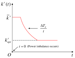
The designed VDIC strategy needs modifications for practical engineering applications. First, according to (11), when , ; thus, considering the physical constraints of the FFRs in practice, the droop coefficient needs a upper bound . Second, when , . The droop control will lose the steady-state frequency support capability if . Hence, to give consideration to both the transient inertia support and the steady-state frequency support of the VDIC strategy, the droop coefficient also needs a lower bound . The lower bound is usually set as the optimal constant droop coefficient corresponding to a steady-state optimal control objective, e.g., the optimal droop coefficient in [7] for power imbalance allocation. Moreover, since is the total droop coefficient of multiple FFRs, in practical engineering, we need to appropriately allocate among the FFRs, e.g., allocating in proportion to the power regulation margins of the FFRs. With the above modifications, the time-domain diagram of the droop coefficient of the modified VDIC strategy is shown in Fig. 1 (red line).
III Case Study
In our previous work [7], a P-f droop control strategy is designed for conventional HVDC systems to provide fast emergency power support. Hence, in this section, we select the HVDC systems as the FFRs to verify the effectiveness of the VDIC strategy. In fact, the VDIC strategy can be applied to all types of FFRs. The test system is a hybrid AC-DC system where four HVDC systems are connected to an IEEE New England system. The electromagnetic transient (EMT) model of the test system is built on the CloudPSS platform [8]. For detailed topology of the test system, we refer to [7].
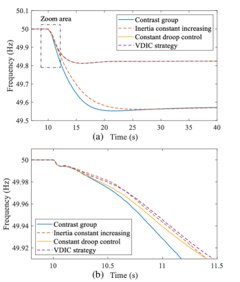
In this test system, the HVDC systems are implemented with the droop control, while the generators are implemented with relatively slow primary frequency control. We set the power base-value of the test system as MVA. The actual inertia constant of the system is s, and the required equivalent inertia support is assumed to be s. We suppose that the upper bound and optimal value of the droop coefficient of each HVDC are 32 p.u. and 8 p.u.; thus, the upper bound and optimal value of the total droop coefficient are p.u. and p.u.. We set a power imbalance MW at the time of 10 s. Based on the above settings, four subcases are simulated to verify the effectiveness of the VDIC strategy: (i) The actual system inertia constant remains unchanged and the droop control of the HVDCs is disabled (contrast group). (ii) The actual system inertia constant increases by . (iii) The HVDCs adopt the droop control with the constant droop coefficient . (iv) The HVDCs adopt the VDIC strategy with the time-invariant droop coefficient in Fig. 1. The simulation results of the system frequencies in the above subcases are shown in Fig. 2.
Since the RoCoFs are negative in a period of time after the power imbalance MW, in the following analysis, the “RoCoF” refers to the “absolute value of the RoCoF”, i.e., the frequency with a larger RoCoF changes faster. First, according to Fig. 2, within approximately 0.5 s after the power imbalance, the frequency changes in subcase (i) and (iii) are nearly identical; later, compared to the RoCoF in subcase (i), the RoCoF in subcase (iii) gradually decreases, which shows that the constant droop control of the HVDCs provides time-variant equivalent inertia support, and this inertia support increases gradually over time. Second, within approximately 1 s after the power imbalance, the frequencies in subcase (ii) and (iv) present nearly identical tendencies, and the RoCoFs in these two subcases are smaller than that in subcase (iii), which illustrates that the VDIC strategy has almost the same effect as actually increasing the system inertia constant in the post-fault initial period. Moreover, the steady-state frequency in subcase (iv) is closer to the nominal value than that in subcase (ii); thus, the VDIC strategy can provide both the transient equivalent inertia support and the steady-state frequency support. The above analysis verifies the effectiveness of the VDIC strategy.
IV Conclusion
In this letter, we quantitatively investigate the equivalent inertia provided by the droop control of FFRs. First, an equivalent-scenario-based method is proposed to evaluate the equivalent inertia provided by the droop control, which shows that the droop control with a constant droop coefficient provides time-variant equivalent inertia support. Second, we design the VDIC strategy with a time-variant droop coefficient for the FFRs. The VDIC strategy can provide the required constant equivalent inertia support without introducing generator-like dynamics, and thus avoids causing system oscillations. In the case study where the HVDC systems are selected as the FFRs, the effectiveness of the proposed VDIC strategy is verified.
References
- [1] F. Milano, F. Dörfler, G. Hug et al., “Foundations and challenges of low-inertia systems,” in 2018 power systems computation conference (PSCC). IEEE, 2018, pp. 1–25.
- [2] M. Chen, D. Zhou, and F. Blaabjerg, “Modelling, implementation, and assessment of virtual synchronous generator in power systems,” J. Mod. Power Syst. Clean Energy, vol. 8, no. 3, pp. 399–411, 2020.
- [3] L. Shang, X. Dong, C. Liu et al., “Fast grid frequency and voltage control of battery energy storage system based on the amplitude-phase-locked-loop,” IEEE Trans. Smart Grid, vol. 13, no. 2, pp. 941–953, 2022.
- [4] W. Du, Q. Fu, and H. Wang, “Power system small-signal angular stability affected by virtual synchronous generators,” IEEE Trans. Power Syst., vol. 34, no. 4, pp. 3209–3219, 2019.
- [5] X. Meng, J. Liu, and Z. Liu, “A generalized droop control for grid-supporting inverter based on comparison between traditional droop control and virtual synchronous generator control,” IEEE Trans. Power Electron., vol. 34, no. 6, pp. 5416–5438, 2019.
- [6] J. Van de Vyver, J. D. De Kooning, B. Meersman et al., “Droop control as an alternative inertial response strategy for the synthetic inertia on wind turbines,” IEEE Trans. Power Syst., vol. 31, no. 2, pp. 1129–1138, 2016.
- [7] Y. Liu, Y. Song, Z. Wang et al., “Optimal emergency frequency control based on coordinated droop in multi-infeed hybrid AC-DC system,” IEEE Trans. Power Syst., vol. 36, no. 4, pp. 3305–3316, 2021.
- [8] Y. Liu, Y. Song, Z. Yu et al., “Modeling and simulation of hybrid AC-DC system on a cloud computing based simulation platform-CloudPSS,” in 2018 2nd IEEE Conference on Energy Internet and Energy System Integration (EI2). IEEE, 2018, pp. 1–6.