Experimental demonstration of superdirective spherical dielectric antenna
Abstract
An experimental demonstration of directivities exceeding the fundamental Kildal limit, a phenomenon called superdirectivity, is provided for spherical high-index dielectric antennas with an electric dipole excitation. A directivity factor of about 10 with a total efficiency of more than 80% for an antenna having a size of a third of the wavelength was measured. High directivities are shown to be associated with constructive interference of particular electric and magnetic modes of an open spherical resonator. Both analytic solution for a point dipole and a full-wave rigorous simulation for a realistic dipole antenna were employed for optimization and analysis, yielding an excellent agreement between experimentally measured and numerically predicted directivities. The use of high-index low-loss ceramics can significantly reduce the physical size of such antennas while maintaining their overall high radiation efficiency. Such antennas can be attractive for various high-frequency applications, such as antennas for the Internet of things, smart city systems, 5G network systems, and others. The demonstrated concept can be scaled in frequency.
I Introduction
Utilization of dielectrics as high-Q resonators, which gave birth to the first concepts of all-dielectric antennas [1, 2, 3], has a long history stretching back more than a century ago [4, 5, 6, 7]. Such antennas became attractive for various high frequency applications due to numerous advantages, including small physical size, simplicity of design and production, high temperature tolerance, corrosion resistance, high radiation efficiency, wide frequency range, adaptive polarization, ease of integration with other antennas and multiple feed systems, and stable radiation patterns. This prospect has become appealing with the advent and rapid development of communication networks with significantly increased amount of transmitted data [8, 9, 10, 11]. An increased interest in the application of all-dielectric antennas based on spherical resonators is witnessed in numerous theoretical [12, 13, 14, 15, 16, 17, 18, 19, 20, 21, 22, 23, 24, 25] and experimental [26, 27, 28, 29, 30, 31, 32, 33, 34, 35, 36, 37, 38, 39, 40] works. Antennas made of materials with simultaneously high refractive index and low losses became increasingly interesting in recent years. Due to a large contrast with the environment, such antennas have small radiation leakage, facilitated by high Q-factors of resonances. In the optical band, high-index dielectric nanoparticles have been employed for enhancing the direction-selective absorption and emission of nanoantennas [41, 42, 43].
The radiation pattern of an antenna is determined by the interference of excited electric and magnetic modes of an open resonator. To obtain a directional design, it is necessary to have constructive mode interference in a given direction and destructive in other directions. The maximum directivity of an antenna is usually considered to be constrained by the so-called Kildal [44, 45] limit,
| (1) |
The limit is expressed solely in terms of the antenna “size parameter”, , where is the radius of the sphere circumscribing the antenna and is the free-space wave number. Note in passing that this limit does not always work for electrically small dielectric antennas [46, 47, 25]. The antennas that exceed this limit are called superdirective. It is possible to obtain electrically small superdirective antennas [48, 49, 50, 51, 52]. Alas such antennas become inefficient [53] as their size decreases, because they require relatively high currents to radiate even low powers. Strong currents lead to an increase in Ohmic losses and large reactive fields near the antenna. Even if Ohmic losses can be significantly reduced by using materials with a low loss angle for the resonator (tan ), the issue of increasing reactive fields is not so easy to resolve. An increase in the dielectric constant of the resonator with decreasing size leads to a greater localization of the field of internal [23] (or interior [7]) modes inside the resonator and to an increase in sensitivity to the slightest changes inside the resonator antennas (e.g., the location and shape of the feeding element).
In view of the above challenges, it has not been obvious that an experimental realization of small superdirective dielectric resonant antennas with practical parameters were feasible. In this work we demonstrate the existence of such designs via numerical optimization and direct measurements. Moreover, we will show that even very simple designs consisting of a homogeneous dielectric sphere fed by an electric dipole source can meet the superdirectivity requirements while retaining a reasonable bandwidth. In what follows, our theoretical approach, experimental details and measured data are described.
II Methods
II.1 Theory
The main parameters characterizing an antenna are the directivity, , gain, , and the realized gain, . The directivity is a dimensionless parameter determined by a relation of the power emitted in some direction to an average of the emitted power over the full solid angle:
| (2) |
Here is the normalized radiation pattern. is determined solely by the shape of the antenna pattern and does not take into account the antenna radiation efficiency, , nor the reflection losses due to an impedance mismatch.
The gain of an antenna, , is related to the directivity by , where is the antenna radiation efficiency (). The realized gain, , is the gain of an antenna reduced by its impedance mismatch factor [54] and related to the directivity through the total antenna efficiency () by the formula . In the measurement setup considered in this work (see Fig. 1), the gain, , and realized gain, , can be derived from the Friis transmission equation [55] for the line-of-sight communication between two antennas in a lossless medium (air)[56]:
| (3) |
| (4) |
where is the polarization mismatch factor (in our case ), is the reflection (mismatch) efficiency, is the free space wavelength, refers to the power provided to a transmission line attached to an emitting antenna, refers to the power received from a transmission line attached to a receiving antenna. is the reflection coefficient for impedance mismatch between the antenna and a transmission line. Subscripts ‘’ and ‘’ are used here for transmitting antenna (superdirective antenna under study) and the receiving horn antenna. is the gain of the receiving horn antenna in the direction strictly oriented to the transmitting antenna (measured by the two-antenna method [57]).
A general physical picture of light scattering by a spherical particle under plane wave illumination is well described by the Lorenz–Mie theory [58], where the solution is represented as an infinite multipole series of partial vector spherical waves. The theory provides an exact solution regardless of the wavelength and the size of the sphere. The Lorenz–Mie theory was later generalized to the case of a point dipole excitation source [14]. Note in passing that such an analytical solution is only available for perfectly spherical surfaces. Any other geometric shapes require more sophisticated numerical methods [59, 60].
The physics underlying resonant scattering behavior of a dielectric resonator is the excitation of its electrical and magnetic modes. Resonant modes of an open spherical resonator can be found from exact analytical formulas for a homogeneous sphere [7, 58]. For the respective TEℓmq and TMℓmq modes these formulas are
| (5) |
Here and are the usual spherical Bessel function of the first kind and the spherical Hankel function of the second kind [61], respectively, stands for multipole order, index labels the subsequent roots of Eqs. (LABEL:eq:char_eq), is the refractive index of the sphere material, is the radius of the homogeneous sphere, and is a free space wavenumber. The equations above are independent of the azimuthal mode number due to the spherical symmetry. All modes with different are degenerate in frequency [7].
For spherical resonators with high refractive index, approximate conditions for excitation of the electric TMℓmq and magnetic TE(ℓ+1)mq modes are closely related. They can be roughly estimated in the limit , in which case Eqs. (LABEL:eq:char_eq) reduce to
| (6) |
with being the -th zero of the -th order spherical Bessel functions of the first kind (see Table 1). Approximate Eq. (6) can be used for a quick and easy estimate of the frequency position of the relevant resonator modes.
At the first stage of this work, initial designs with high directivity were obtained by performing optimization using the analytical solution for a sphere excited by a point electric dipole [14]. In order to precisely match the experiment, a subsequent optimization was performed in the CST Studio Suite [62] taking into account a finite and realistic dipole size and connector cables. During optimization, our search for optimal parameters of the dipole was performed by varying (i) the position of the dipole, (ii) the thickness and length of the dipole arms, (iii) their offset and bend radius, (iv) the distance between the dipole arms. A frequency shift of resonance was achieved, if required, by changing either the resonator permittivity or its size. The above approach allowed us to obtain the designs of directional antennas with high total antenna efficiency under realistic conditions, closely matching the experiment.
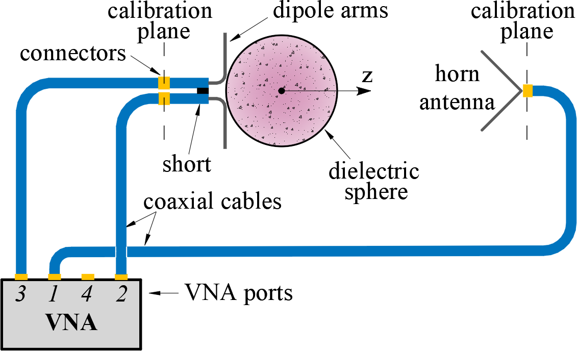
II.2 Experimental setup and measurements
Experimental measurements of the directivity were carried out in an anechoic chamber using R&SZVB Vector Network Analyzer (VNA). The horn antenna was mounted on a triaxial positioner. The antenna under study was located on a special foam pedestal on a rotary positioner (see photographs in Section I of the supplementary materials). As indicated in Fig. 1, experimental data were obtained using a three-port connection to the VNA by measuring the S-parameters in the planes and with a angle step of (see Section II of the supplementary materials). The secant plane of includes the -axis and the arms of the dipole, while the plane of is perpendicular to the arms of the dipole.
The measurements were carried out within GHz band with a frequency resolution of Hz. The antenna under study is located in the far field of the horn antenna at a distance of meters. To implement an electric dipole, two coaxial cables with a characteristic impedance of located side by side were used. The arms of the dipole were made from the inner conductors of coaxial cables with a diameter of mm. As illustrated in Fig. 1, the horn antenna was connected to the physical port of the VNA, which was represented by a logical port . The physical ports and were connected to the dipole arms and combined into a differential logical port .
The quantity describing the transmission from the balanced port with differential mode stimulus to the single-ended port was measured in the experiment. The radiation pattern in Eq. (2) is determined as divided by , where the maximum is taken over all possible angular directions. The ratio in Eq. (3) is equal to the measured value . The reflection coefficients for each antenna are and . In general, all the -parameters can be obtained by measuring reflection and transmission between individual ports in accordance with the theory describing multiport experimental measurements [63, 64]:
| (7) |
where the subscript ’s’ stands for the single mode, ’d’ - for the differential mode, and ’c’ - for the common mode.
III Results
III.1 External dipole
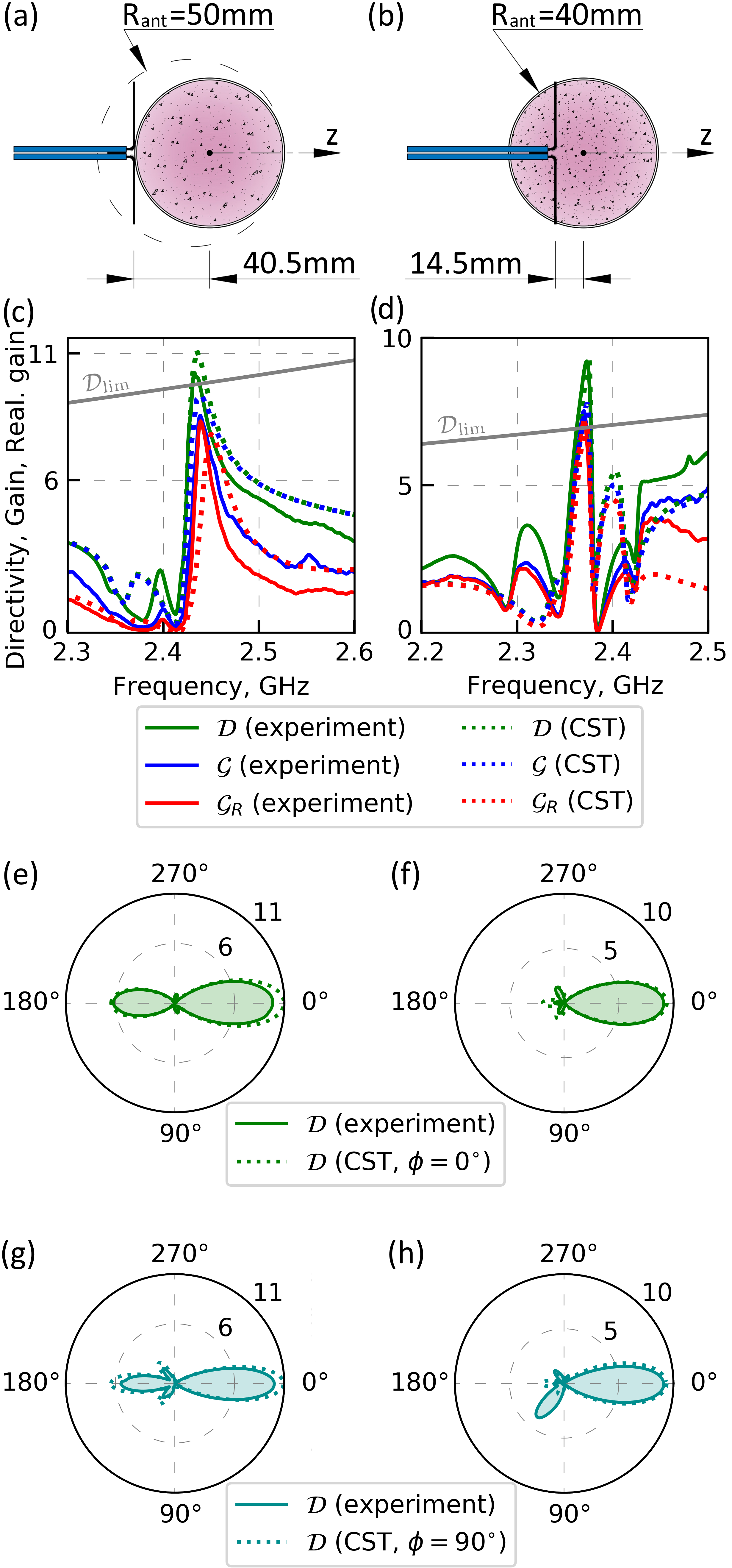
In order to achieve the superdirective regime, we first considered a dipole located near a spherical resonator – a system which might be one of the most interesting from a practical viewpoint and the simplest for an experimental implementation. The dielectric antenna was made in the form of a plastic ball filled with ceramic powder and excited externally by an electric dipole as shown in Fig. 2(a). The length of the dipole arms is mm, the gap between the centers of the cables supplying the dipole is mm. The plastic shell made of acrylic with a thickness of mm has an outer radius mm, the real part of permittivity , and the loss tangent . Free Flowing Dielectric Powder ECCOSTOCK HiK has the real part of permittivity and the loss tangent . Vibrations were used to obtain a dense packaging of the ceramic powder inside the spherical resonator.
The plastic shell used in this work exclusively to set up the shape of the resonator was taken into account in all our calculations. The thickness of the dielectric shell is times less than the thickness of the main layer with dielectric powder. Given that the characteristics of the shell are much closer to air than to the powder, the results with and without the shell appear pretty much the same (see Section IV of the supplementary materials).
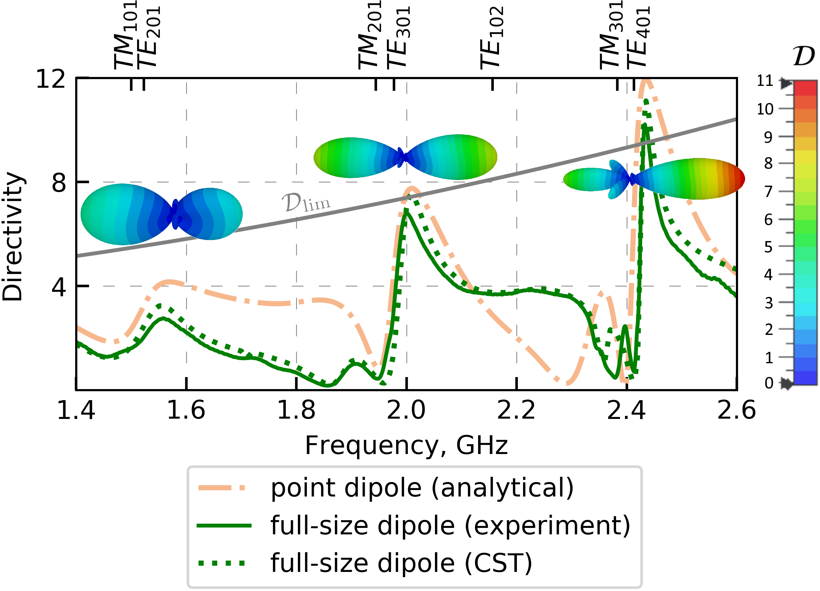
At the first stage, an interval containing the frequencies of the first eigenmodes of a homogeneous spherical resonator was considered. Figure 3 shows a comparison of the directivity calculated analytically for a sphere excited by a tangentially oriented point dipole with the results obtained by the full-size simulation in CST Studio Suite and measured experimentally. Experimental results seem to agree well with the simulations. At the same time, the analytical point dipole model [14] describes quite well the position and magnitude of jumps in the directivity. Such Fano-type [36] directivity behavior near resonant frequencies arises due to the interaction of a relatively narrow magnetic mode (of the order of ) with a broad electric mode (of the order of ).
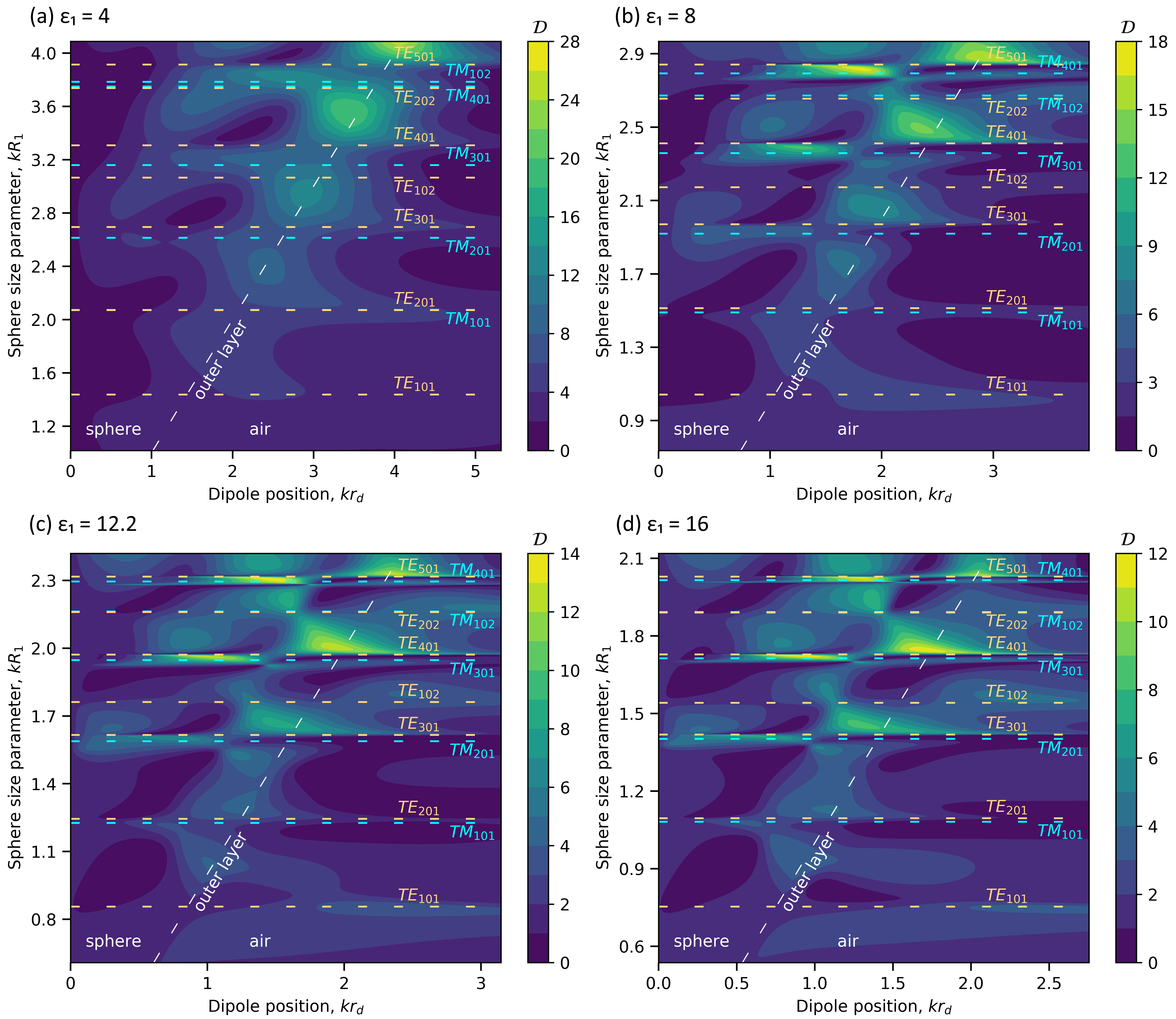
Figure 2(c) shows numerical and experimental results for directivity, gain and realized gain in forward direction versus frequency. The data are given for the frequency range GHz in the vicinity of the directivity resonance. The experimentally obtained directivity of the antenna reaches at frequency GHz. The half-power beamwidths (HPBWs) obtained numerically were equal to and for the and planes, respectively. In the experimental results, HPBWs were and for the indicated planes. There is a reasonable agreement between the experimental data calculated by formulas (2)–(4) and the simulation results obtained with the CST Studio Suite within the entire demonstrated frequency range. High total antenna efficiency is achieved at an antenna impedance close to , resulting in minimal energy reflection back to the port and maximum radiation to the environment. The physics underlying the resonant directional behavior for the system under consideration is simultaneous excitation of the electric TM301 and magnetic TE401 modes of the sphere by the electric dipole and constructive interference of the radiation in the forward direction. This is easy to check, since for these two modes of the spherical resonator the approximate relation is satisfied (see Eq. (6)).
Figures 2(e) and 2(g) provide a comparison of the experimental and numerical radiation patterns in two planes ( and ) for the resonant frequency of GHz shown in Figure 2(c). The difference between the experimentally measured and numerically calculated diagrams in Figs. 2(e,g) is associated with the effect of radiation from the coaxial cable feeding the antenna under test due to the currents arising on the cable surface: (i) for on the horizontal section of the cable, (ii) for on the vertical one. The radiation pattern outside the resonant frequency is affected also by side lobes that arise uncontrollably due to the imperfection of the antenna.
III.2 Internal dipole
Although the use of a spherical resonator makes it possible to obtain the superdirectional radiation, the matched dipole located outside has a significant length and increases the overall size of the antenna (the circumscribing sphere). This makes it difficult to exceed Kildal’s limit (Eq. (1)) while maintaining high total antenna efficiency. Therefore, we also considered the case of the electric dipole located inside a spherical dielectric resonator. The antenna with a dipole inside was made in the form of a plastic ball, similar to the antenna described above, but with an exciting electric dipole located inside, as shown in Fig. 2(b). The dipole was fixed in pre-perforated holes at three points of the plastic sheath: at the place where the cable crosses it, and at the ends of the dipole arms. Then, the small gaps remaining in the holes were sealed with a hot glue and after that the powder was poured into the shell. Fabrication and measurement processes are presented in Section I of the supplementary materials. The receiving horn antenna and the transmitting antenna were located at meters distance in this case.
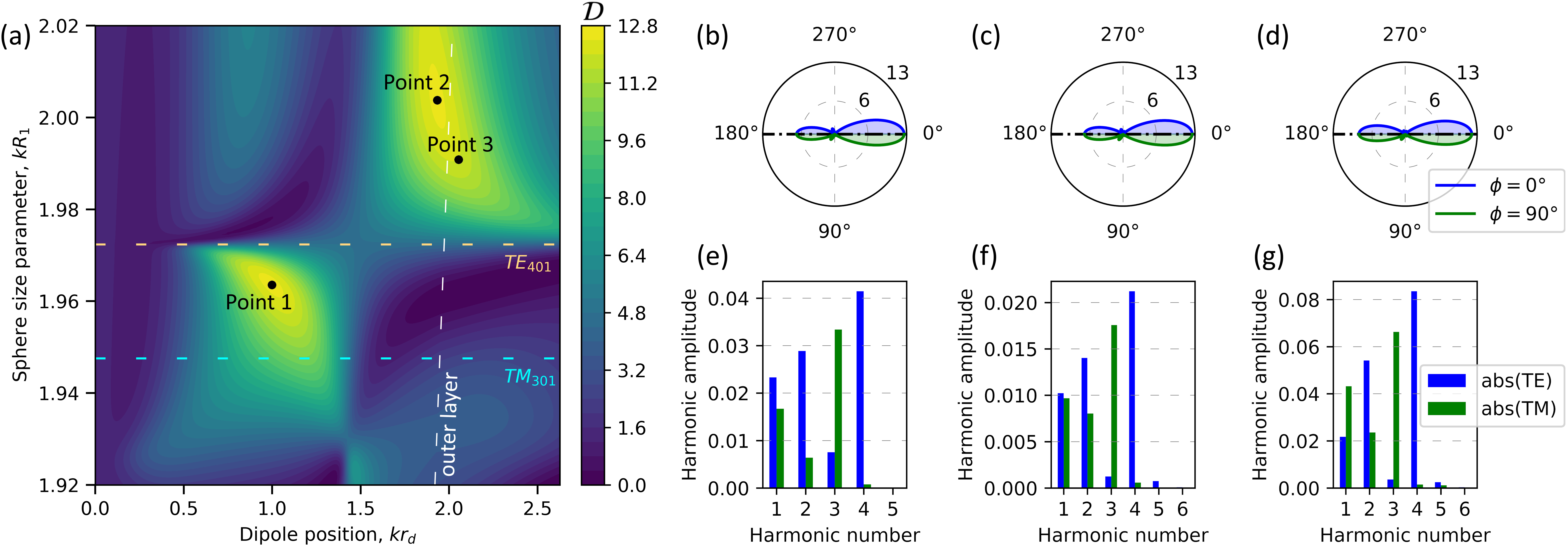
The internal modes of a high-index dielectric spherical resonator are generally more efficiently excited from within its interior [25]. For initial search of the optimal position of the dipole, a homogeneous spherical antenna excited by a tangentially oriented point dipole was considered. Figure 4 shows the directivity in the forward direction as a function of the dimensionless parameter of antenna size and dipole position for several values of permittivity. It is noticeable that with increasing the dielectric constant, the geometric size of the resonator decreases and the quality factor of the resonances increases. Figure 5 shows an enlarged fragment of Figure 4(c) near the resonant condition of the TE401 mode. For the points with the maximum directivity, the dependence of the directivity on the angle in the planes and are plotted and the corresponding multipole expansions are displayed. It turns out that the ratio of harmonic amplitudes is approximately the same for both the point dipole located inside and at the resonator boundary. By means of full-size optimization, the optimal position of the dipole is chosen on the -axis and shifted by mm from the center of the sphere, which places the dipole arms near the zone with the highest directivity in Figure 5 (marked point (a)). The length of the dipole arms was mm, the gap between the centers of the cables was mm. Such an experimental setup enables one to reduce the radius of the antenna circumscribing sphere down to mm, i.e. to the size of the dielectric spherical resonator.
Figure 2(d) shows numerical and experimental results for directivity, gain and realized gain as a function of frequency in the -direction. The data are given for the frequency range GHz in the vicinity of the directivity resonance. The experimentally measured radiation patterns at the resonant frequency of GHz in two planes are shown in Figures 2(f) and 2(h). The directivity of the antenna reaches in the direction . The antenna exceeds Kildal limit while maintaining high total antenna efficiency at the resonant frequency. The HPBWs that were numerically obtained are and for the and planes, respectively. In the experimental results, HPBWs are and for the indicated planes.
An increase in directivity can also be achieved for an external dipole by immersing the dipole under the outer surface of the resonator (point (b) in Figure 5). Using a small notch on the surface to place a dipole inside can also produce super-directional radiation, as has been numerically demonstrated in Ref. 32.
IV Discussion
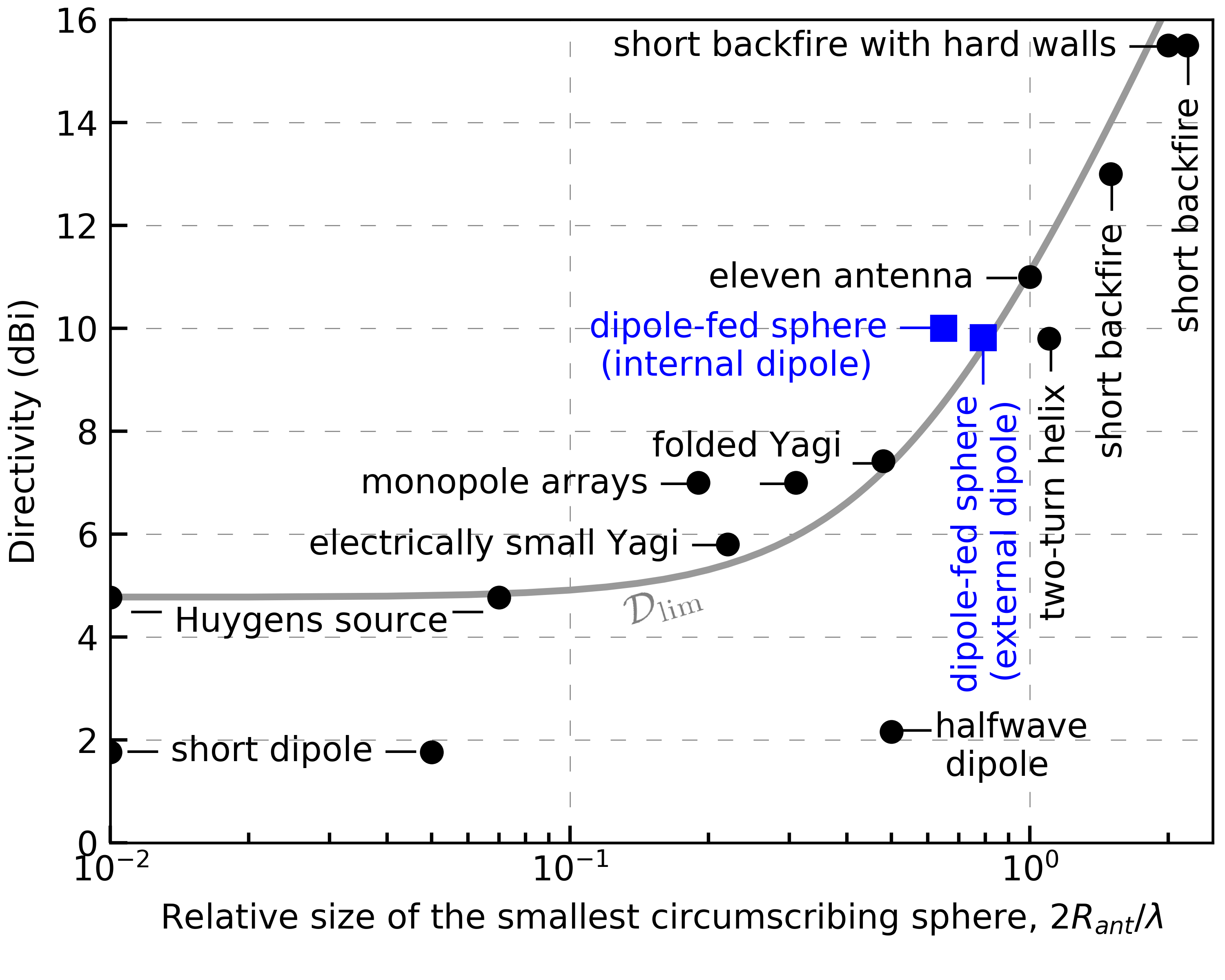
Figure 6 shows a comparison of our results with available experimental data (Fig. 3 of Ref. 45). Our results unambiguously demonstrate that it is possible to obtain both highly efficient and superdirective radiation simultaneously. Without taking into account the radiation efficiency it is possible to arrive at even higher directivity values by about for the same homogeneous sphere at a given resonance.
In view of potential applications, an assessment of antenna tolerances and possible sources of errors for both numerical and experimental data deserves particular attention. The analytical solution of an ideal point-like dipole problem of Ref. 14 can be reproduced with machine accuracy. For a more realistic description of the experimental setup, a three-dimensional electrodynamic problem was developed in the CST Studio Suite by means of the frequency domain solver [62]. Those simulations can also be tuned to yield numerically accurate solutions. Though, incremental changes in some geometrical parameters, e.g. in a configuration of the feeding cables, were found to cause significant changes in the S-parameters in some spectral regions. Given that assessing these parameters experimentally is very difficult, there could be relatively large uncertainties related to their values even for relatively simple models as considered here [57]. Experimental data, including finite calibration tolerances (), inaccuracies in the spatial orientation and position of the transmitting and receiving antennas (), polarization loss (), noise (), parasitic reflections and radiation from equipment, not ideal parameters of the cables, dipole, and dielectric resonator are the largest source of potential uncertainties and errors. Also, the directivity was evaluated with the S-parameters that were measured in only two planes ( and ), which also bring an error related to the realistic pattern deviations when rotating around the z-axis.
Surface irregularities and/or inhomogeneity of the sphere material lead to frequency splitting of excited modes with different magnetic number , which leads to violation of the superdirectivity. Superdirective antennas have been in theory often considered with an infinite ground plane (see examples in Ref. 45), which is not taken into account when calculating the practical antenna size. However, in experimental realizations, this ground plane is comparable to the size of the antenna and can have a significant impact on the distribution of near fields.
Regarding practical realization of the directivity limit a number of issues have to be taken into account. It is important to understand that the frequency bandwidth significantly decreases in the limit , which, together with the requirements on manufacturing quality, makes it impossible to use theoretically obtained resonances in practice. On the other hand, when , it is as a rule impossible to excite well separated electric and magnetic modes of a spherical resonator at a given frequency. We believe that the value of used in our experiment is a reasonable compromise for demonstrating the superdirectivity effect when operating at the required modes.
To design a super-directional antenna similar to the described one with the internal dipole, the following steps can be proposed. First, one should choose a sphere with a refractive index and size allowing for its TE401 eigenmode to be at a desired operating frequency (see Eqs. (LABEL:eq:char_eq) and (6)). Next, for the required , an approximate optimal dipole position is selected on the basis of point dipole approximation (see Fig. 4). Finally, a full-scale simulation and fine-tuning of the dipole parameters is carried out in order to minimize the return loss at the resonant frequency. The shape of the feed element can be further optimized to improve matching and reduce dependence on the position of the dipole inside the resonator.
Finally, it is important to mention the issue of the antenna bandwidth. This is an ambiguous parameter [56], specifically for electrically small antennas. Typically, such antennas have low total radiation efficiency, whereas in our measurements, the radiation efficiency exceeded within the MHz frequency band, and the corresponding directivity reached the values of for the case with an external dipole, and for the case with an internal dipole.
V Conclusion
The novelty of our work lies in that a spherical dielectric resonator can facilitate an antenna of a simple design having superdirectional radiation in a given direction. The use of high-index, low-loss ceramics allows one to significantly reduce the physical size of antennas, while maintaining a high overall radiation efficiency and practical bandwidth. We have demonstrated both numerically and experimentally the possibility of superdirectional behavior for antennas smaller than the wavelength based on a spherical dielectric resonator with a dipole source. The antenna directivity is maintained at the frequencies of eigenmodes of the spherical resonator, provided that one appropriately adjusts the position of the dipole source. Our results can be extrapolated to a wide range of radio [65, 66, 67, 68, 69], and optical [34, 70, 71, 72, 73] frequencies with a suitable choice of high-index materials, while taking into account the cost, availability, and safety of the materials, as well as their compatibility with the desired manufacturing method. It should also be noted that reducing the size of the antenna leads to the main problem of all electrically small antennas, namely the problem of impedance matching. Unfortunately, this problem is fundamental and as the size decreases, the maximum achievable overall radiation efficiency of the antenna also decreases [74, 75, 53]. An ideal solution for this problem has not yet been obtained. Therefore, when the size of the antenna is greatly reduced relative to the wavelength, the maximum directivity can remain approximately the same, but the efficiency-dependent gain and the realized gain will decrease.
SUPPLEMENTARY MATERIAL
See the supplementary material for details related to the fabrication process of the antenna and more detailed data obtained during the measurements.
ACKNOWLEDGMENT
Theoretical part of the work was supported by the Russian Science Foundation (Project No. 21-79-30038). Experimental part of the work was supported by the Priority 2030 Federal Academic Leadership Program.
AUTHOR DECLARATIONS
Conflict of interest
The authors declare that they have no competing interests.
DATA AVAILABILITY
The data that support the findings of this study are available from the corresponding author upon reasonable request.
References
- Long et al. [1983] S. A. Long, M. W. McAllister, and L. C. Shen, IEEE Trans. Antennas Propag. 31, 406 (1983).
- McAllister et al. [1983] M. W. McAllister, S. A. Long, and G. L. Conway, Electron. Lett. 19, 218 (1983).
- McAllister and Long [1984] M. W. McAllister and S. A. Long, Electron. Lett. 20, 657 (1984).
- Debye [1909] P. Debye, Annalen der Physik 335, 57 (1909).
- Richtmyer [1939] R. D. Richtmyer, J. Appl. Phys. 10, 391 (1939).
- Stratton [1941] J. Stratton, Electromagnetics Theory (McGraw-Hill, 1941).
- Gastine et al. [1967] M. Gastine, L. Courtois, and J. L. Dormann, IEEE Trans. Microwave Theory Tech. 15, 694 (1967).
- Shafi et al. [2017] M. Shafi, A. F. Molisch, P. J. Smith, T. Haustein, P. Zhu, P. De Silva, F. Tufvesson, A. Benjebbour, and G. Wunder, IEEE J. Sel. Areas Commun. 35, 1201 (2017).
- Zhang et al. [2019] Z. Zhang, Y. Xiao, Z. Ma, M. Xiao, Z. Ding, X. Lei, G. K. Karagiannidis, and P. Fan, IEEE Veh. Technol. Mag. 14, 28 (2019).
- Lin et al. [2019] W. Lin, R. W. Ziolkowski, and J. Huang, IEEE Trans. Antennas Propagat. 67, 3670 (2019).
- Tataria et al. [2021] H. Tataria, M. Shafi, A. F. Molisch, M. Dohler, H. Sjöland, and F. Tufvesson, Proc. IEEE 109, 1166 (2021).
- Van Bladel [1975] J. Van Bladel, IEEE Trans. Microw. Theory Tech. 23, 208 (1975).
- Chew [1987] H. Chew, J. Chem. Phys. 87, 1355 (1987).
- Moroz [2005] A. Moroz, Ann. Phys. 315, 352 (2005).
- Evlyukhin et al. [2010] A. B. Evlyukhin, C. Reinhardt, A. Seidel, B. S. Luk’yanchuk, and B. N. Chichkov, Phys. Rev. B 82, 045404 (2010).
- Arslanagic et al. [2011] S. Arslanagic, M. Mostafavi, R. Malureanu, and R. W. Ziolkowski, Proc. EUCAP , 2064 (2011).
- Balanis [2012] C. A. Balanis, Advanced engineering electromagnetics, 2nd ed. (John Wiley & Sons, Inc., 2012).
- Krasnok et al. [2014a] A. E. Krasnok, C. R. Simovski, P. A. Belov, and Y. S. Kivshar, Nanoscale 6, 7354 (2014a).
- Liu [2015] W. Liu, Opt. Express 23, 14734 (2015).
- Arslanagić and Ziolkowski [2017] S. Arslanagić and R. W. Ziolkowski, IEEE Antennas Propag. Mag. 59, 14 (2017).
- Li et al. [2018] R. Li, X. Zhou, M. Panmai, J. Xiang, H. Liu, M. Ouyang, H. Fan, Q. Dai, and Z. Wei, Opt. Express 26, 28891 (2018).
- Rasskazov et al. [2019] I. L. Rasskazov, A. Moroz, and P. S. Carney, J. Opt. Soc. Am. A 36, 1591 (2019).
- Wang et al. [2019] Z. Wang, B. Luk’yanchuk, L. Yue, B. Yan, J. Monks, R. Dhama, O. V. Minin, I. V. Minin, S. Huang, and A. A. Fedyanin, Sci. Rep. 9, 20293 (2019).
- Majic and Le Ru [2020] M. Majic and E. C. Le Ru, Appl. Opt. 59, 1293 (2020).
- Gaponenko et al. [2021] R. Gaponenko, A. Moroz, I. L. Rasskazov, K. Ladutenko, A. Shcherbakov, and P. Belov, Phys. Rev. B 104, 195406 (2021).
- Wong et al. [1993] K. L. Wong, N. C. Chen, and H. T. Chen, IEEE Microw. Guided Wave Lett. 3, 355 (1993).
- Filonov et al. [2012] D. S. Filonov, A. E. Krasnok, A. P. Slobozhanyuk, P. V. Kapitanova, E. A. Nenasheva, Y. S. Kivshar, and P. A. Belov, Appl. Phys. Lett. 100, 1 (2012).
- Evlyukhin et al. [2012] A. B. Evlyukhin, S. M. Novikov, U. Zywietz, R. L. Eriksen, C. Reinhardt, S. I. Bozhevolnyi, and B. N. Chichkov, Nano Lett. 12, 3749 (2012).
- Kuznetsov et al. [2012] A. I. Kuznetsov, A. E. Miroshnichenko, Y. H. Fu, J. Zhang, and B. Luk’yanchuk, Sci. Rep. 2, 1 (2012).
- Geffrin et al. [2012] J. M. Geffrin, B. García-Cámara, R. Gómez-Medina, P. Albella, L. S. Froufe-Pérez, C. Eyraud, A. Litman, R. Vaillon, F. González, M. Nieto-Vesperinas, J. J. Sáenz, and F. Moreno, Nat. Commun. 3, 1171 (2012).
- Rolly et al. [2013] B. Rolly, J. M. Geffrin, R. Abdeddaim, B. Stout, and N. Bonod, Scientific Reports 3, 3063 (2013).
- Krasnok et al. [2014b] A. E. Krasnok, D. S. Filonov, C. R. Simovski, Y. S. Kivshar, and P. A. Belov, Appl. Phys. Lett. 104, 133502 (2014b).
- Krasnok et al. [2014c] A. E. Krasnok, E. A. Krasnok, D. S. Filonov, P. V. Kapitanova, and P. A. Belov, in 44th EuMC (2014) pp. 676–678.
- Kuznetsov et al. [2016] A. I. Kuznetsov, A. E. Miroshnichenko, M. L. Brongersma, Y. S. Kivshar, and B. Luk’yanchuk, Science 354, aag2472 (2016).
- Tribelsky et al. [2015] M. I. Tribelsky, J.-M. Geffrin, A. Litman, C. Eyraud, and F. Moreno, Sci. Rep. 5, 12288 (2015).
- Tribelsky et al. [2016] M. I. Tribelsky, J.-M. Geffrin, A. Litman, C. Eyraud, and F. Moreno, Phys. Rev. B 94, 121110 (2016).
- Tsuchimoto et al. [2016] Y. Tsuchimoto, T. Yano, T. Hayashi, and M. Hara, Opt. Express 24, 14451 (2016).
- Forestiere et al. [2020] C. Forestiere, G. Miano, and G. Rubinacci, Phys. Rev. Research 2, 043176 (2020).
- Sinev et al. [2020] I. Sinev, F. Komissarenko, I. Iorsh, D. Permyakov, A. Samusev, and A. Bogdanov, ACS Photonics 7, 680 (2020).
- Powell et al. [2021] A. W. Powell, A. P. Hibbins, and J. R. Sambles, Appl. Phys. Lett. 118, 251107 (2021).
- Rolly et al. [2012] B. Rolly, B. Stout, and N. Bonod, Opt. Express 20, 20376 (2012).
- Ziolkowski [2017] R. W. Ziolkowski, Phys. Rev. X 7, 031017 (2017).
- Monti et al. [2022] A. Monti, S. H. Raad, Z. Atlasbaf, and A. Toscano, Opt. Lett. 47, 2386 (2022).
- Kildal [2007] P.-S. Kildal, in Proc. 2nd Eur. Conf. Antennas Propag. (Institution of Engineering and Technology, Edinburgh, UK, 2007) pp. 16–25.
- Kildal et al. [2017] P.-S. Kildal, E. Martini, and S. Maci, IEEE Antennas Propag. Mag. 59, 16 (2017).
- Bouwkamp and de Bruijn [1945] C. J. Bouwkamp and N. G. de Bruijn, Philips Res. Rep. 1, 135 (1945).
- Uzkov [1946] A. Uzkov, in Comptes Rendus (Doklady) de l’Academie des Sciences de l’URSS, Vol. 53 (1946) pp. 35–38.
- Newman and Schrote [1982] E. Newman and M. Schrote, IEEE Trans. Antennas Propag. 30, 1172 (1982).
- Yaghjian et al. [2008] A. D. Yaghjian, T. H. O’Donnell, E. E. Altshuler, and S. R. Best, Radio Sci. 43, 1 (2008).
- Haskou et al. [2016] A. Haskou, A. Sharaiha, and S. Collardey, IEEE Antennas Wirel. Propag. Lett. 15, 24 (2016).
- Ta et al. [2017] S. X. Ta, I. Park, and R. W. Ziolkowski, IEEE Access 5, 14657 (2017).
- Shi et al. [2022] T. Shi, M.-C. Tang, R. Chai, and R. W. Ziolkowski, IEEE Transactions on Antennas and Propagation 70, 5288 (2022).
- Karlsson [2013] A. Karlsson, PIER 136, 479 (2013).
- IEE [2014] IEEE Std 145-2013 (Revision of IEEE Std 145-1993) , 1 (2014).
- Friis [1946] H. T. Friis, Proc. IRE 34, 254 (1946).
- Balanis [2016] C. A. Balanis, Antenna theory. Analysis and design, 4th ed. (John Wiley & Sons, Inc., Hoboken, New Jersey, 2016).
- Ant [2022] IEEE Std 149-2021 (Revision of IEEE Std 149-1977) , 1 (2022).
- Bohren and Huffman [1998] C. F. Bohren and D. R. Huffman, Absorption and scattering of light by small particles (John Wiley & Sons, 1998).
- Waterman [1971] P. C. Waterman, Phys. Rev. D 3, 825 (1971).
- Mishchenko [2014] M. I. Mishchenko, Electromagnetic Scattering by Particles and Particle Groups (Cambridge University Press, 2014).
- Abramowitz and Stegun [1964] M. Abramowitz and I. A. Stegun, eds., Handbook of mathematical functions with formulas, graphs, and mathematical tables (U.S. Department of Commerce, National Bureau of Standards, 1964).
- [62] CST, “Studio suite 2021, https://www.3ds.com/products-services/simulia/products/cst-studio-suite/,” .
- Fan et al. [2003] W. Fan, A. Lu, L. L. Wai, and B. K. Lok, in Proc. EPTC (IEEE, 2003) pp. 533–537.
- Rohde & Schwarz [2004] Rohde & Schwarz, “Measuring Balanced Components with Vector Network Analyzer ZVB,” (2004).
- Luk and Leung [2003] K.-M. Luk and K.-W. Leung, eds., Dielectric Resonator Antennas (SRP Ltd., Exeter, Great Britain, 2003).
- Narang and Bahel [2010] S. B. Narang and S. Bahel, J. Ceram. Process. Res. 11, 316 (2010).
- Parshin et al. [2018] V. V. Parshin, E. A. Serov, E. E. Chigryai, B. M. Garin, R. N. Denisiuk, D. S. Kalyonov, M. Ding, L. Li, Y. Lu, Y. Yang, Y. Liang, J. Feng, and P. V. Ershova, J. Radio Electron. 2, 1 (2018).
- die [2008] in Dielectric Materials for Wireless Communication, edited by M. T. Sebastian (Elsevier, 2008) Chap. Appendix 2, pp. 541–652.
- Ohsato et al. [2018] H. Ohsato, J. Varghese, and H. Jantunen, in Electromagnetic Materials and Devices, edited by M.-G. Han (IntechOpen, Rijeka, 2018) Chap. 1.
- Smirnova and Kivshar [2016] D. Smirnova and Y. S. Kivshar, Optica 3, 1241 (2016).
- Baranov et al. [2017] D. G. Baranov, D. A. Zuev, S. I. Lepeshov, O. V. Kotov, A. E. Krasnok, A. B. Evlyukhin, and B. N. Chichkov, Optica 4, 814 (2017).
- Tzarouchis and Sihvola [2018] D. Tzarouchis and A. Sihvola, Appl. Sci. (Switz.) 8, 184 (2018).
- Odit et al. [2021] M. Odit, K. Koshelev, S. Gladyshev, K. Ladutenko, Y. Kivshar, and A. Bogdanov, Adv. Mater. 33, 1 (2021).
- Harrington [1960] R. F. Harrington, J. Res. Natl. Bur. Stan. Sect. D. Rad. Prop. 64D, 1 (1960).
- Hansen [2006] R. C. Hansen, Electrically Small , Superdirective , and Superconducting Antennas (John Wiley & Sons, Inc., Hoboken, New Jersey, 2006).