Dynamic Programmable Wireless Environment with UAV-mounted Static Metasurfaces
Abstract
Reconfigurable intelligent surfaces (RISs) are artificial planar structures able to offer a unique way of manipulating propagated wireless signals. Commonly composed of a number of reconfigurable passive cell components and basic electronic circuits, RISs can almost freely perform a set of wave modification functionalities, in order to realize programmable wireless environments (PWEs). However, a more energy-efficient way to realize a PWE is through dynamically relocating static metasurfaces that perform a unique functionality. In this paper, we employ a UAV swarm to dynamically deploy a set of low-cost passive metasurfaces that are able to perform only one electromagnetic functionality, but with the benefit of requiring no power. Specifically, the UAV-mounted static metasurfaces are carefully positioned across the sky to create cascaded channels for improved user service and security hardening. The performance evaluation results, based on ray tracing, demonstrate the potential of the proposed method.
Index Terms:
Wireless propagation, UAVs, Metasurfaces, RIS, Security, Energy Efficiency.I Introduction
Recently, a wireless communication paradigm has emerged, which strives to constitute the wireless propagation phenomenon into a software-defined and deterministic process [1]. This direction, denoted as programmable wireless environments (PWEs), is enabled via coating planar objects in a space with metasurfaces, more recently known as reconfigurable intelligent surfaces (RISs). RISs constitute a merge of metasurfaces with well-defined networking and programming interfaces. Employing the Huygens principle, RIS can manipulate impinging waves by altering their power, direction, polarization, and phase [2]. Thus, RIS can be dynamically orchestrated to realize custom end-to-end propagation routes, e.g., to avoid unintended users, increase the quality of the wireless channels, or even realize futuristic applications such as extended reality [1, 3, 4].
PWEs are presently combined with flexible unmanned aerial vehicles (UAVs) which carry RIS units to carefully selected places and configure their electromagnetic behavior dynamically [5], [6],[7]. While promising, this approach burdens with additional cost and power consumption an already high-cost and energy-restricted UAV system. In this work, we explore a direction where only inexpensive, static metasurface units are required to dynamically create a PWE. Specifically, inspired by late trends in UAV-based delivery of goods [8], we consider a set of UAVs, where each one can dynamically position a metasurface, which can only serve a specific wave manipulation functionality, such as steering an impinging wave to a specific direction of departure. Therefore, by following an orchestration process, the UAVs can fine-tune these static metasurface units properly to form cascading channels [9] and, thus, improve the quality-of-service (QoS) of the network users in terms of connectivity and security. Hence, compared to synergetic UAV-RIS networks, the proposed approach has the benefit of low-cost and simplicity, as the UAV-orchestrated metasurfaces can transform a wireless propagation environment into a dynamic PWE.
II UAV-Deployable PWE with static metasurfaces
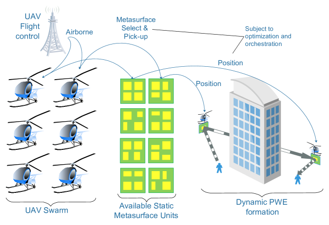
Fig. 1 represents a schematic of the proposed system architecture. We consider an environment hosting wireless users, with multiple blockages present. In this setting, a UAV swarm is licensed to operate under the command of a UAV flight control system. Each UAV in the swarm can be dynamically equipped with one static metasurface, available at the premises of the UAV ground station. Each metasurface can serve only one static wave manipulation functionality, such as steering from and to very specific wave directions of arrival and departure.
The UAV flight control is assumed to be delegated a communication assistance task by a third-party communication system, which monitors its users and deduces the connectivity requirements. Subsequently, it invokes the UAV flight control to dynamically deploy a PWE in the premise of the users in need of assistance or communication augmentation. The UAV flight control then executes a UAV-driven PWE orchestration algorithm and deduces the static metasurfaces to be deployed at the user premises, in a way that end-to-end cascaded air links and channels are formed. Following the orchestration planning phase, the UAV control instructs a set of UAVs in the swarm to pick up the selected RIS units and move to positions designated by the orchestration process. Once there, the channel is deployed automatically, without further deliberations.
We proceed to detail the specifications and workflow of each component of the proposed architecture, i.e., the UAV flight control and orchestration system, the static metasurface units, and the dynamic PWE orchestration and configuration process.
II-A UAV flight control and orchestration system
As a UAV fleet scales horizontally, efficient management methods are required to ensure its safety and high performance in terms of placement and energy requirements [8]. Therefore, controlling a UAV swarm is a complex operation that requires a fully automated and omniscient orchestrator, which is a crucial software component of any UAV network to guarantee its continuous operation.
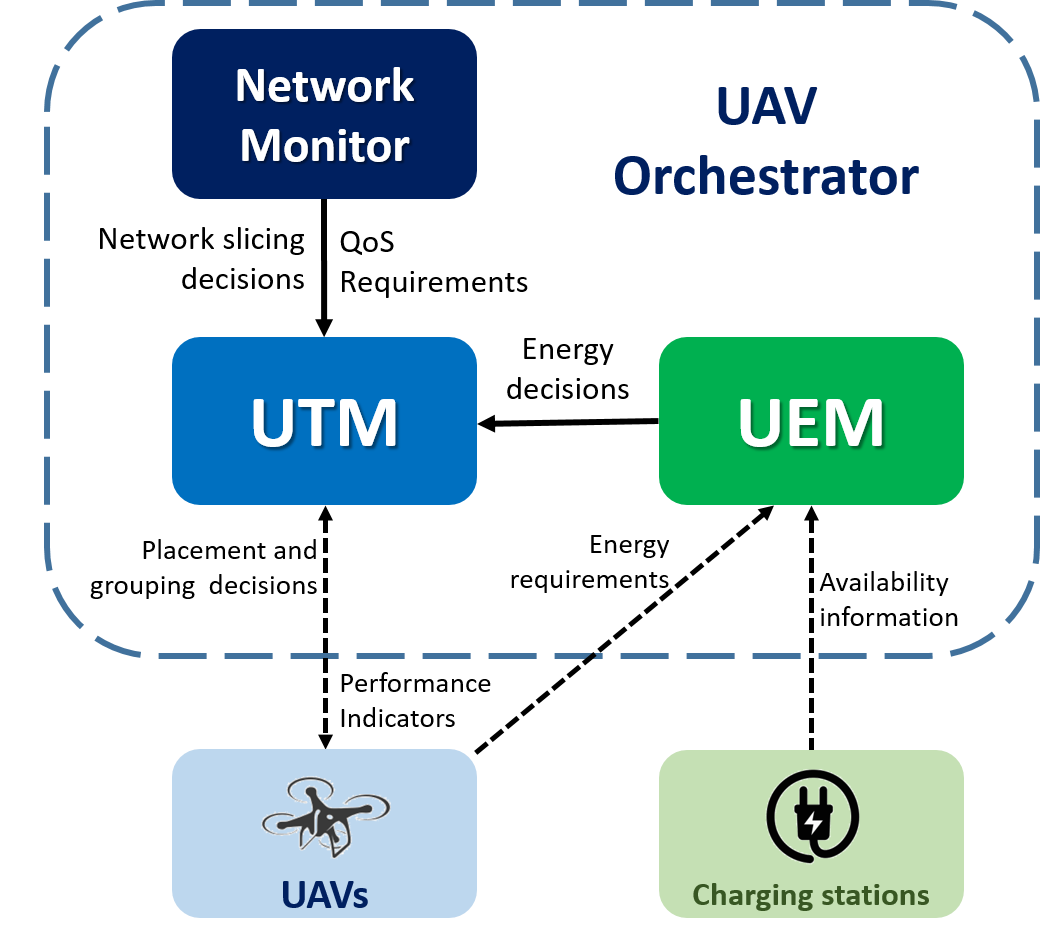
In a nutshell, the UAV orchestrator consists of three main components:
-
•
UAV Traffic Manager (UTM): The UTM is the main brain of the orchestrator. It is responsible for the placement of the UAVs while taking into account various restrictions and feedback from other components, such as the UAV energy requirements, the client QoS requirements, the weather conditions, and the airspace authorization. Moreover, it is responsible for grouping the UAV network to allow the division of the network for different use cases.
-
•
UAV Energy Manager (UEM): One of the major limitations in the UAV operation is their energy needs. The UEM is responsible for preventing power outages of UAVs and handling their recharging through charging stations [10]. The decisions made by the UEM are delivered at the UTM for appropriate mobility actions and resource allocation.
-
•
Network Monitor: The network monitor is aware of the QoS needs of each specific client, as well as the needs of the different use cases that would enable possible UAV network slicing procedures. Therefore, it informs the UTM to take appropriate actions on the UAV placement and grouping, respectively.
In Fig. 2, we present the information flow among the different UAV orchestrator components.
II-B Non-programmable Metasurfaces
Metasurfaces are composite materials exhibiting engineered macroscopic electromagnetic (EM) properties. They comprise specifically EM-tuned and spatially-arranged unit cells (or meta atoms) that collectively interact with the impinging wavefront to provide a given scattered (e.g., reflected) wavefront; embedding reconfigurable components (e.g., PIN diodes) in the cells allows active control of the response. Metasurfaces can control most aspects of the scattered wavefront, e.g., its amplitude, direction/phase, polarization, even frequency. The efficiency of this control scheme is determined by the unit cell architecture and the performance of the embedded components. Given the complexities of the underlying physical mechanisms, simplified methods for calculating the metasurface configuration-response relation have been proposed, such as antenna arrays with phase and amplitude control per element or equivalent circuit models. These serve distinct purposes in defining the accessible metasurface functions [2].
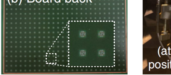
Notably, this description refers to reprogrammable metasurface units, where the embedded switches are controlled via software. Thus, the same metasurface can be tuned in real-time to serve different types of wave manipulation functionalities. However, one can replace the dynamically switching elements with passive and non-tunable electronic packages, offering fixed impedance to the traversing signals. When properly selected in this manner, one can manufacture non-programmable metasurface units that serve a very specific functionality, such as full wave absorption from a given angle of incidence, anomalous steering for a given set of specific angles (arrival and departure), anomalous -way splitting, etc. Such a metasurface example, manufactured with printed circuit board technology, is given in Fig. 3 [11]. Moreover, metasurfaces can offer the benefits of requiring no power to operate and no need for networking capabilities. As such, if one possesses a UAV control system and a set of metasurfaces, one can also deploy a PWE dynamically.
II-C PWE deployment and configuration abstracted
Deploying a PWE dynamically requires a macroscopic approach in its modeling and configuration. To this end, we revisit the PWE graph, , introduced in [1]. This model considers a graph where each user device and each RIS is a vertex . Moreover, we add one edge between two vertexes that are within LOS. Given this graph, it should be also considered a user that employs edges to connect to RIS around it. Furthermore, we assume an access point that is connected to of the total RIS units. The PWE configuration is then equivalent to finding vertex-disjoint paths that connect each to any . Once such paths are found, e.g., via the algorithms presented in [1], they can be instantiated by deploying the corresponding wave steering commands to each RIS represented by the vertexes upon each path.
However, in the studied UAV-driven PWE case, metasurface units are not fixed in terms of location. In addition, the considered units can serve only one specific wave manipulation functionality, such as reflecting a given direction of wave arrival to a given direction of wave departure. This approach makes the PWE configuration more dynamic, opening a future research challenge. In the context of this short paper, we outline a greedy solution as follows. We mark a set of possible UAV points in space and add them to the graph. Then, we execute the outlined PWE configuration algorithm. Once the paths are found, we observe how many of the returned vertexed paths can be served by the available set of metasurface units and their static wave steering angles. We mark those units and corresponding vertexes as “busy”, and we remove the non-busy path vertexes from the graph. Subsequently, we attempt to reconnect gaps in the intended air links, but iteratively execute a path-finding algorithm, e.g., Dijkstra, between the gap end-points, and then repeat the process until the path is formed (or until a given set of retries expires).
Notably, the proposed algorithm does not account for limitations in the UAV swarm or runtime concerns. Focusing here on a proof of concept, we define these concerns to be in the scope of extensions of the present study.
III Evaluation
We proceed to evaluate the use of a UAV-deployed PWE in a simple setting, using a PWE simulator [1]. The objective is to perform an initial comparison in a ray-tracing setting, and in a simple geometry, using regular propagation (non-PWE) as a baseline.
|
|
|
![[Uncaptioned image]](/html/2211.14882/assets/x3.png)
| UAV flight Height | |
|---|---|
| RIS Dimensions | |
| RIS Functions | Steer |
| Frequency | |
| Tx Power | |
| Antenna type | Single -lobe sinusoid, |
| pointing at (cf. Table I) | |
| Power loss per bounce | % |
We consider a transmitter (Tx)-receiver (Rx) pair in the floorplan and setup shown in Table I, which consists of a Tx and an Rx on the plane, separated by a perfect absorber (red wall) between them. The device positions and setup geometry are given in Table I. The antenna radiation patterns are simple sinusoids of angle , pointed towards opposite directions, making natural communication unlikely. Transmission parameters are given in Table II.
We define possible UAV locations (red areas in Table I, with inter-spacing). Moreover, we assume that 15 UAVs are available, as well as a set of static metasurface units, which are enough to serve any possible set of wave propagation angles that can be formed in the setup. Subsequently, we execute the process described in Section II-C.
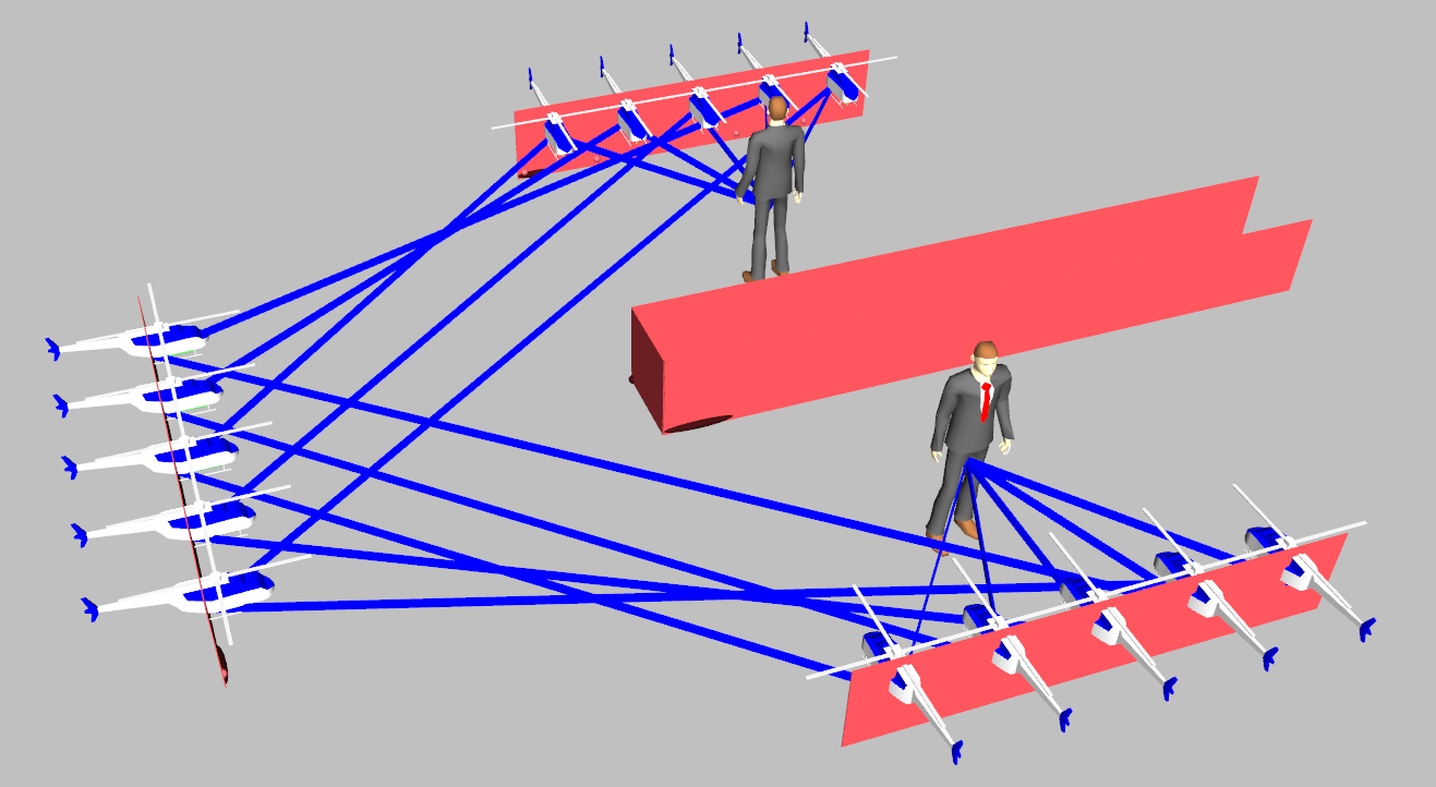
Visualizations of the ray-traced outcome of the UAV-driven PWE are given in Fig. 4. Using all available UAV positions, the dynamically formed PWE steers all major rays propagated by the Tx to the Rx. In this way, the middle obstacle (red wall) is bypassed during the wireless propagation phenomenon.
| Regular propagation (no PWE) | No signal |
| UAV-driven PWE |
The received power per scheme is given in Table III. Notably, the employed setup offers no natural connectivity. On the other hand, the UAV-driven PWE approach restores connectivity and yields a received power of .
IV Conclusion
This work presented a way of dynamically deploying PWEs with the aid of UAVs but under the condition of employing static metasurfaces which serve a specific wave manipulation functionality. Each UAV of the swarm selects and mounts an available passive metasurface, and proceeds to position itself within a space to form cascaded wireless channels for user serving. The work concluded by presenting a simulated example of the proposed approach operation, showing that the UAV-driven PWE can effectively restore connectivity.
Acknowledgment
This work was funded by projects HERMES (EU Horizon 2020, GA 891515), WISAR (Foundation for Research and Technology–Synergy Grants 2022) and COLLABS (EU Horizon 2020, GA 871518).
References
- [1] C. Liaskos, A. Tsioliaridou, S. Nie, A. Pitsillides, S. Ioannidis, and I. F. Akyildiz, “On the network-layer modeling and configuration of programmable wireless environments,” IEEE/ACM Transactions on Networking, vol. 27, no. 4, pp. 1696–1713, 2019.
- [2] A. Li et al., “Metasurfaces and their applications,” Nanophotonics, vol. 7, no. 6, pp. 989–1011, 2018.
- [3] K. K. Nguyen, A. Masaracchia, V. Sharma, H. V. Poor, and T. Q. Duong, “RIS-Assisted UAV Communications for IoT With Wireless Power Transfer Using Deep Reinforcement Learning,” IEEE Journal of Selected Topics in Signal Processing, vol. 16, no. 5, pp. 1086–1096, 2022.
- [4] C. Liaskos et al., “XR-RF Imaging Enabled by Software-Defined Metasurfaces and Machine Learning: Foundational Vision, Technologies and Challenges,” IEEE Access, pp. 1–1, 2022.
- [5] L. Yang, F. Meng, J. Zhang, M. O. Hasna, and M. Di Renzo, “On the performance of RIS-assisted dual-hop UAV communication systems,” IEEE Transactions on Vehicular Technology, vol. 69, no. 9, pp. 10 385–10 390, 2020.
- [6] D. Tyrovolas, P.-V. Mekikis, S. A. Tegos, P. D. Diamantoulakis, C. K. Liaskos, and G. K. Karagiannidis, “On the Performance of HARQ in IoT Networking with UAV-mounted Reconfigurable Intelligent Surfaces,” in 2022 IEEE 95th Vehicular Technology Conference: (VTC2022-Spring), 2022, pp. 1–5.
- [7] J. Ye, J. Qiao, A. Kammoun, and M.-S. Alouini, “Non-terrestrial Communications Assisted by Reconfigurable Intelligent Surfaces,” Proceedings of the IEEE, vol. 110, no. 9, pp. 1423–1465, 2022.
- [8] K. T. San, S. J. Mun, Y. H. Choe, and Y. S. Chang, “UAV delivery monitoring system,” in MATEC Web of Conferences, vol. 151. EDP Sciences, 2018, p. 04011.
- [9] D. Tyrovolas, S. A. Tegos, E. C. Dimitriadou-Panidou, P. D. Diamantoulakis, C. K. Liaskos, and G. K. Karagiannidis, “Performance analysis of cascaded reconfigurable intelligent surface networks,” IEEE Wireless Communications Letters, vol. 11, no. 9, pp. 1855–1859, 2022.
- [10] P.-V. Mekikis and A. Antonopoulos, “Breaking the Boundaries of Aerial Networks with Charging Stations,” in ICC 2019 - 2019 IEEE International Conference on Communications (ICC), 2019, pp. 1–6.
- [11] A. Pitilakis et al., “Multifunctional Metasurface Architecture for Amplitude, Polarization and Wave-Front Control,” Phys. Rev. Applied, vol. 17, p. 064060, Jun 2022. [Online]. Available: https://link.aps.org/doi/10.1103/PhysRevApplied.17.064060